Test Cases Generation For Distributed Real-Time Software Systems
8
0
0
全文
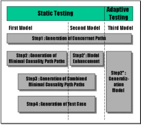
(2) environment can only be presented during the valid interval of data. Temporal consistency can be achieved only if data items are accessed within their valid intervals. The temporal consistency requirement of data together with the fast response time requirements of the supported application establishes timing constraints for the transactions processed in the system. The primary scheduling goal in real-time systems is to satisfy the timing constraints of transactions. The system must provide schedules that guarantee deadlines. Nuclear power plants, air traffic control systems, process control systems, and robotics are some examples of applications that usually process hard deadline transactions. Soft deadline transactions are scheduled based on their deadlines, and satisfaction of deadlines is still the primary performance goal in scheduling transactions; however, in this case, there is no guarantee that all deadlines will be met. A soft deadline transaction is executed until completion regardless of whether its deadline has expired or not. Firm deadline transactions also do not carry strict deadlines, i.e., missing a deadline may not result in a catastrophe, but unlike soft deadline transactions, they are aborted by the system once their deadlines expire. Typically, no value will be imparted to the system if a firm deadline transaction misses its deadline. 2.2.2 Evaluation Issue for Distributed Real-Time Control Software Systems In general, there are some difficulties in certifying software quality in the distributed environment. There are special requirements of testing communication applications. It is necessary to test the client's user interface, the client's interface with the server, the server's functionality, and the network. The most important point in testing process is the test case generation [2]. In section 2.3, we induce two current survey approaches, and section 3 illustrates the statistical usage testing. Finally, comparing their advantages and disadvantages. 2.3 Current survey Testing is an activity which consists of extracting knowledge from an Implementation Under Test (IUT). One would like to check that a given IUT meets some properties. In the case of conformance testing, such properties are defined from the protocol specification. A main difficulty of protocol testing is that the IUT is a black box, i.e. a system whose internal structure and behavior are unknown to the tester. This implies that testing consists of stimulating the implementation (by its interfaces) in order to observe its behavior. There are two black-box testing approaches: 2.3.1 On the Fly Approach Test Selection Algorithm There are some steps in on the fly approach [3]: Modeling communicating entities: the behavior of a. communicating entity can be described by means of transition systems such as Input Output Automata and Input Output State Machines(IOSM). Modeling test purpose: a Test Purpose (TP) is a property that one would like to observe/check on implementation behaviors. The conformance of implementation can be defined by means of requirements or test purpose sets. A test purpose defines a temporal sequencing of observable actions. So we model it with a finite automaton. The test experiment must be controllable and the TP automaton must take this feature into account. Observation and test purpose: a test case is an execution pattern that meets a given TP running a test case can be considered as a kind of synchronous execution of implementations and test purpose. Test execution is successful when an accepting state of TP is reached. Selection of such test cases consists of traversing the graph obtained from the synchronization between the implementation model and the TP model. Test selection algorithm: we need to compute an execution path that meets both specifications S1, S2 and test purpose TP. In our approach, this computation is performed on the fly, i.e. during exploration of the behavior graph. The on the fly paradigm means that we do not calculate the graph before searching for test pattern. For this purpose, we use a Depth First Search (DFS) algorithm aimed at exploring the behavior graph from the product of S1, S2, TP. The algorithm examines the friability of transitions, and exits as soon as an accepting state of TP is reached. 2.3.2 Finite State Machine Approach Test Case Generation All the procedures in the other approach are showed in fig.1, and steps are discussed following [5]: System Modeling: a concurrent system consists of a number of sequential systems. Each sequential system is modeled as a Finite State Machine (FSM). The environment (e.g., operators, testers, and/or subsystems which are not under test) of a concurrent system is also modeled as FSMs. It is assumed that there is no global physical clock, that is, the system model is asynchronous. The FSMs communicate with each other by messages and are assumed to contain no message loops. Generation of Concurrent Paths: a path is a sequence of events performed by an FSM starting and ending in the same initial state and is denoted as e1->e2->…->em. We consider, for simplicity, the second visit to the initial state of an FSM as termination. This is not a limitation since subsequent behavior (if any) can be viewed as another path. Generation of Minimal causality Path: enumerate all possible event sequences by inter-leaving while satisfying the conditions. Generation of Combined Minimal Causality Path: the Combined Minimal Causality Path (CMCP) is a connected directed graph from which test sequences for a concurrent system are generated. The vertices and edges of the graph correspond, respectively, to the global states of the 2.
(3) concurrent system and the global events in an Minimal Causality Path (MCP). Test Case Generation: we have derived CMCP, which is equivalent to the control flow graph in [4]. According to [4], test sequences can be obtained from the control flow graph using the same methods for test case derivation of a single Deterministic FSM (DFSM), namely transition tour [6], UIO, W, Wp method and others. Although each method applied to CMCP may give rise to a different test sequence with different coverage.. constitute a script for use in testing. They may be annotated during test planning to include instructions for conducting and evaluating tests, and they may be annotated during testing to record results and observations. Test cases may be applied by human testers or used as input to an automated test tool. 3.3 Benefits of Statistical Testing Based on a Usage Model Statistical usage testing of a software system produces measures of product and process quality for management decision making throughout the life cycle. Because a usage model is based on specifications rather than code, the insights that result from model building can be used to make informed management decisions in the early stages of a project when the opportunity to prevent problems is greatest. The following are key benefits of usage modeling and statistical testing [8]. 3.3.1 Validation of Requirements. Fig. 1 Overall procedure of 3. STATISTICAL USAGE TESTING Statistical usage testing (SUT) is always separated into two major parts: usage model and test cases generation. We will discuss below[8]: 3.1 Building Usage Model Base on Markov Chain The initial structure of a usage model follows directly from the software specification[14]. In particular [11, 12, 13], the canonical sequences identified during specification define the initial state space for the usage model. A usage model may be represented as a graph in which the nodes represent usage states and the arcs represent stimuli that cause transitions between usage states. Note that it is states of use that are referred to here, and not internal stales of the software. Developers and potential users, who often participate in usage model review, easily understand graphical usage models. Graphical representation aids in system understanding but is generally only used for small systems or for high-level representation of large systems. Usage models for large systems are often defined abstractly at first, with automated support for model expansion through sub-models and transformation of abstract stimuli to associated atomic stimuli. 3.2 Generating Test Cases Statistically After the usage model has been developed, test cases can be generated automatically by traversing the usage states of the model[11, 12, 15], guided by the transition probabilities associated with the exit arcs from each state. Because each arc is associated with a particular stimulus to the system, the traversal results in an accumulation of successive stimuli that represents a particular test case. The test cases. A usage model is an external view of the system specification that is readily understandable by system engineers, developers, customers, and end users. Interfaces and requirements are often simplified or clarified when the usage model (including possible inputs, possible sequencing of inputs, and expected outputs) is reviewed systematically in the context of operational use. 3.3.2 Resource and Schedule Estimation Standard calculations on a usage model provide data for effort, schedule, and cost projections, such as the minimum number of tests required to cover all states and transitions in the model. "What-if" analyses can be conducted to bind the best and worst case out comes of testing based on failure data. 3.3.3 Grafted, Nonrandom Test Cases Special test cases, perhaps required by contract or regulation, can be determined by examining the model to be sure that certain sequences are tested. Existing test cases can be mapped to the model to assess omissions or redundancy. The usage model becomes a reference model for all testing required or desired. Automated Test Case Generation. A minimal coverage test script (the minimal number of test events for complete coverage of the usage model) and random test cases (based on the usage probability distribution) can be generated automatically from a usage model. Model coverage testing ensures a minimal level of function before random testing begins, and random testing provides a basis for estimating operational reliability. 3.3.4 Effective, Efficient Testing Faults are not equally likely to cause failures. Faults that are on frequently traversed paths have a higher probability of causing failures than faults that are on infrequently traversed paths. This simple fact is the primary motivation for random testing: Faults are discovered in roughly the 3.
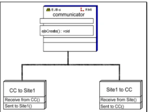
(4) order in which they would cause failures in the field. The test budget is spent in a way that maximizes the increase in operational reliability resulting from testing. 3.3.5 Focused Testing (Biased Sampling) Usage models support biased sampling of sequences of special interest, such as infrequently used but critical functions. Separate models can be developed for these functions, or the original model may be transformed, sampled, and the results corrected to remove the bias. 3.3.6 Quantitative Test Management Statistical testing based on a usage model provides quantitative criteria for management decisions about completion of testing and system release. The sufficiency of testing can be measured as the statistical difference between expected usage (as represented in the usage model) and tested usage (as recorded in testing).. Fig. 2 the system architecture of the communication project. 3.3.7 Estimate of Reliability Using a statistical testing protocol, a valid estimate of expected operational performance can be derived from the performance of the software during testing. The actual test results (i.e., correct and incorrect performance on each input) are recorded as weights on the usage model, and calculations on the model provide estimates of reliability in operational use. Fig. 3 UML use case diagram of communication system 4. DEMONSTRATION EXAMPLE A sequence-based specification will be created for the communication project using the stepwise process described in the preceding subsection. 4.1 System Description in a Communication Project This example system is combined by three parts of sub-system, including CC, communicator, and site stations, as show in Fig.1and Fig.2 illustrates use case diagram. In the case, we consider only site1 station. In CC, there are five components: CC receives data process, CC process, CC 60-seconds counter, CC sends TM, and CC send process. It is similar to the site1 station, where CC receive data process is responsible for receiving the message that sent by the site1 station send TM.. Fig. 4 UML class diagram of CC station. Fig. 5 UML class diagram of site1 station. 4.
(5) possible scenarios of use: sequences of length zero (the empty sequence), length one (single stimulus), length two (single-stimulus extensions of the sequences of length one), and so on. Enumeration ends when all sequences of a given length are either illegal or equivalent to a previous sequence. Again, an illegal sequence is one that is "impossible," such as S-SS-AS. Also, one sequence is equivalent to another if the two sequences have identical future behavior. 4.5 Define State Fig. 6 system architecture of communicator 4.2 Tagged Requirements Tagging of requirements is the first step in creating a traceable specification, as shown in Table 1. Subsequent elements of the specification will be traced to their origin in the requirements through these tags. As each step in the specification is traced lo the relevant requirement, ambiguities and omissions in the requirements will be discovered. When there is no requirement to cite in a trace, a "derived" requirement will be stated and tagged as D1, D2, and so on. 4.3 System Boundary Definition and All Stimulus We should first define the system boundary, there is one possible source of stimuli to the system: the detector of CC receive component. After analysis the specification of system, defining all stimuli inside the boundary. The following table lists all stimuli.. State data encapsulates and retains the components of stimulus history that must be preserved for the system to produce correct responses. Examining the canonical sequences in the enumeration identifies the essential components of stimulus history. Each canonical sequence is examined to identify the unique conditions in the sequence, and state variables are invented to represent the conditions. 4.6 Construct the Usage Model The canonical sequences identified during security alarm specification define the state space for the usage model. Each canonical sequence is named to represent the usage state. The usage model may be drawn using the canonical sequences as states. The ordering of stales can be determined by referring to the canonical sequences, and the full set of possible stimuli given in the sequence enumeration can be used to define all possible transitions (arcs) among states. Fig.5 is a graphical depiction of the usage model for the system. Stimuli that have no effect on the usage state are represented in a self-loop in each state.. In addition to responses that are explicitly defined in the requirements, two other values are often used in sequence-based specification: the null response and illegal. The null response occurs when there is no external system response, such as when a system is ignoring or perhaps accumulating stimuli. Illegal is used when a sequence is impossible, such as when stimuli are presented before invocation.. Stim ulus S AS AP AR SS SP SR. Description Invoke system CC send message CC process CC receive message Site1 station send message Site1 station process Site1 station receive message. Requireme nt Trace No. 0 5 2 1 11 8 7. Fig. 7 usage model of system 4.7 Analysis System Usage Model The built usage model for communication project includes 13 states in all. With the aid of ToolCertify certification tool [16] the analyzed report may be summarized as the Table 2.. Table. 1 lists all stimuli (partially) 4.4 Sequence Enumeration Sequence enumeration involves consideration of all 5.
(6) Number Of Nondeleted States Number Of Active Arcs Expected Script Length Least Likely State Coverage Expected At Least Likely Transition Coverage Expected At Source Entropy. 13 16 7.333333 14.999999 16.000000 0.272727. Table. 2 Analysis report for the system usage model 4.8 Using toolSET_Certify to Generate Test Cases After the usage model and the analysis have been reviewed and determined to be a viable basis for testing, test cases are generated. The first test suite generated is usually the minimal arc coverage suite, which traverses the model in the fewest possible steps required to achieve model coverage. Model coverage testing accomplishes several goals. The model is further confirmed to be accurate, the ability to evaluate all responses is confirmed, and the readiness of the software for random testing is established. Random testing enables measurement of the reliability of the software. If the quality of the software is so poor that it cannot survive arc coverage testing in a reasonable period of time, then the software is not ready for random testing.. Fig. 9Behavior Graph of communication system. 4.9 Generate Test Cases by on the Fly Technique In on the fly approach, according to the previous description, behavior of communication system is illustrated in fig.8.. Fig. 10 Test case in Global Behavior Graph 4.10 Generate Test Cases by FSM Approach In FSM approach, according to the previous description, behavior of communication system is illustrated in fig.11. Among this diagram, a, b, c, d, e, f means that CC sending the message, CC 20 sec. Error, SS sending and processing the message, SS 20 sec. Error, SS 60 sec. Error, and CC 60 sec. Error, respective.. Fig. 8 Behavior of communication system By combining two distributed subsystem: communication center and site1 station. The global behavior graph of communication system is showed in fig.9 and one of the test cases in fig.10.. Fig. 11 Behavior of communication system and. 6.
(7) that, by the compare result, the suggested mechanism is not only feasible but also efficient in locating and recovering potential defects existed in the distributed real-time software systems. 6. REFERENCES [1]. [2] Fig. 12 Part of test cases in the CC. [3]. 4.11 Comparison of the Three Test Cases [4] The advantages of SUT test cases are listed following: 4.11.1 Test with Circle Stimulus In on the fly and FSM approach, there is no circular system behavior, that is, the two approach cannot search for circular usage failure. However, SUT uses usage model that includes circular usage transaction.. [5]. [6]. 4.11.2 Full Usage Model SUT illustrates all the usage specification of users, but on the fly and FSM approach builds its system global behavior in testing, it may stop testing before all situations are taken into consider. 4.11.3 Without Complex Test Algorithm SUT execute each test case step by step according to the description, but on the fly and FSM approaches run test case according to algorithm that tester may need high technology about the approach. 4.11.4 Test Statistically On the fly uses DFS to select test case, sometimes it may finish testing before searching all the usage. In SUT, after building and valid the complete usage, we start choose the test case statistically.. [7] [8]. [9]. [10]. [11]. [12]. 5. CONCLUSION [13] Essentially, the rationale of statistical usage testing is to generate a set of complete test cases systematically, which is rather than the general ad hoc approaches. It may provide complete testing coverage and quantitative analysis as well. This project is to investigate the feasibility of employing the statistical usage testing to software testing in distributed real-time software systems. In this research, a test case generation is proposed to perform distributed testing by the philosophy of statistical usage testing. In addition, this research has demonstrated. [14]. [15]. [16]. Alan Fekete, David Gupta, Victor Luchangco, and Nancy Lynch, “Eventually-serializable data services.” Theoretical Computer Science 220, pp. 113-156, 1999. Avi Silberschatz, Peter Galvin, and Greg Gagne, “Applied Operating System Concepts.” John Wiley & Sons, Inc., pp. 501-563, 2000 Kone´ O. and Castanet R., “Test generation for interworking systems.” Computer Communications 23 (2000), pp. 642–652, 2000 Kajiwara M., H. Ichikawa, M. Itoh, and Y. Yoshida, “Specification and verification os switching software, IEEE Trans. Communi., pp. 193-198, 1985. Myungchul Kim, Jaehwi Shin, Samuel T. Chanson, and Sungwon Kang, “An Approach for Testing Asynchronous Communication System.”IEICE Transition Communication., Vol.E82-B, No.1, 1999. Naito S. and M. Tsunoyama, “Fault detection for sequential machines by transition-tours.” Proc. FTCS(Fault Tolerance Cimputer System, pp. 238-243, 1981. Q-Labs: “Tool_Certify User Guide.” Version 4.0, 1999. Stacy J. Prowell, Carmen J. Trammell, Richard C. Liger and Jesse H. Poore, “Cleanroom Software Engineering Technology and Process.” pp. 46-109, 1999. Trammell C. and J. Poore, “Process Control in Statistical Reliability Certification.” Proceedings of the Seventh Annual Software Software Technology Conference, 1995. Ulusoy Özgür, “Research Issues in Real-Time Database Systems.” Information Sciences, Vol.87, Issue: 1-3, pp. 123-151, 1995. J. A. Whittaker and M. G. Thomason, “A Markov Chain Model for Statistical Software Testing.” IEEE Transactions on Software Engineering, Vol. 20 (10), pp. 812-824, 1994. G. H.Walton, J. H. Poore and C. J. Trammell, “Statistical Testing of Software Based on a Usage Model.” Software Practice and Experience, Vol. 25(1), pp. 97-108, 1995. G.H. Walton, “Optimizing Software Usage Models. Ph.D. Dissertation, Department of Computer Science.” University of Tennessee, 1995. J. A. Whittaker and J.H. Poore, “Markov Analysis of Software Specifications.” ACM Transactions on Software Engineering and Methodology, Vol. 2(1), pp. 93-106, 1993. Whittaker, James A. and J.H. Poore, “Statistical Testing for Cleanroom Software Engineering.” Proceedings of HICSS-25, IEEE, 1992. Whittaker and James A, “Markov Chain Techniques For Software Testing and Reliability Analysis.” Ph.D. 7.
(8) Dissertation, Department of Computer Science, University of Tennessee, Knoxville, TN, 1992. [17] Xuemin Lin, “A fully distributed quorum consensus method with high fault-tolerance and low communication overhead.” Theoretical Computer Science, Volume: 185, Issue: 2, pp. 259-275, 1997. 8.
(9)
數據


+2

相關文件
Tei-Wei Kuo, Embedded System and Wireless Networking Lab, National Taiwan University.. Real-Time
By correcting for the speed of individual test takers, it is possible to reveal systematic differences between the items in a test, which were modeled by item discrimination and
Monopolies in synchronous distributed systems (Peleg 1998; Peleg
OurChain stands for all your blockchains, an autonomous platform for any blockchain, including a ChainAgent, a ChainBrowser, a ChainFoudry, a Ch ainOracle and an OurCoin with
Although many excellent resource synchronization protocols have been pro- posed, most of them are either for hard real-time task scheduling with the maxi- mum priority inversion
This research is focused on the integration of test theory, item response theory (IRT), network technology, and database management into an online adaptive test system developed
In the development of data acquisition interface, matlab, a scientific computing software, was applied to acquire ECG data with real-time signal processing.. The developed
Muraoka, “A Real-time Beat Tracking System for Audio Signals,” in Proceedings of International Computer Music Conference, pp. Goto, “A Predominant-F0 Estimation Method for
