Improving IEEE 802.11 RTS/CTS Handshake in Wireless Ad Hoc Networks Considering Large Interference Range
8
0
0
全文
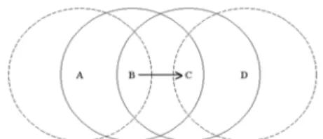
(2) problem. The hidden terminal problem and the exposed terminal problem need to be solved in order to improve the performance in the wireless networks.. proceed. If the medium is determined to be busy, the mobile node shall defer until the end of the current transmission. After deferral, or prior to attempting to transmit again immediately after a successful transmission, the mobile node shall select a random backoff interval and shall decrement the backoff interval counter while the medium is idle.. 2.3. The RTS/CTS Handshake in IEEE 802.11 MAC The main task of a MAC is to avoid collisions. In order to eliminate hidden terminal problems, the IEEE 802.11 MAC protocol defines an optional four-way handshaking technique, known as request-to-send/ clear-to-send (RTS/CTS) mechanism. A mobile node that wants to transmit, follows rules explained in Section 2.1, and then, instead of the data frame, preliminarily transmits a special short frame called request to send (RTS) to reserve the channel. When the receiving node receive the RTS frame, it responds, after a SIFS, with a clear to send (CTS) frame. The transmitting node is allowed to transmit its frame only if the CTS frame is correctly received. All other nodes overhead either the RTS and/or the CTS set their virtual CS indicator, called a network allocation vector (NAV), for the given duration indicated in the RTS/CTS frame and use this information together with the physical carrier sense function when sensing the medium. The NAV state is combined with physical carrier sense function to indicate the busy state of the medium. This mechanism reduces the probability of the receiver side collision caused by a node that is hidden from the transmitter during carrier sense and RTS transmission, because the node overhears the CTS and "reserve" the medium as busy until the end of the transaction. Therefore, all other nodes inside the transmission range of transmitter and/or receiver overhear the RTS/CTS will defer their transmission and thus avoid collisions caused by hidden terminals.. 2.2. The Hidden Terminal and Exposed Terminal Problems The CSMA/CA mechanism was designed to avoid collisions, however, resulted in the hidden terminal problem [5][6] that will cause collisions and exposed terminal problem [6] that will underutilize available bandwidth. A hidden terminal is one that is within the range of the intended receiver but out of range of transmitter. Consider the case shown in Figure 1. Station B is transmitting to station C. Station D cannot hear the transmission from B. During this transmission when D senses the channel, it falsely thinks that the channel is idle. If station D starts a transmission, it interferes with the data reception at C. In this case station D is a hidden terminal to station B. Hence, hidden terminals can cause collisions on data transmission.. Figure 1: Hidden terminal and exposed terminal. Exposed terminals are complementary to hidden terminals. An exposed terminal is one that is within the range of the transmitter but out of range of the receiver. In Figure 1, consider the case that station B is transmitting to station C. Station A can hear the transmission from B. When station A senses the channel, it thinks that the channel is busy. However, any transmission by station A does not reach C, and hence does not interfere with data reception at station C. Ideally, station A can send simultaneously to other receivers without interfering C's reception. In this case, station A is an exposed terminal to station B.. 3.1. The Large Interference Range as a Function of Transmitter-Receiver Distance. Hidden terminals can cause collisions on data transmission while exposed terminals underutilize available bandwidth. If the hidden terminal and exposed terminal problems could not be minimized, the network performance will degrade severely. To increase the range of carrier sensing is a way to eliminate the hidden terminal problem, but it will intensify the exposed terminal. Considering the signal propagation, some nodes that are out of the transmission range of both the transmitter and the receiver, may still interfere with the receiver. This situation happened rarely in the WLAN because almost all the mobile nodes are within each other's transmission range. But in the wireless ad hoc networks, due to the multihop connectivity and ad. 3. Large Interference Range In recent years, more and more researchers have realized large interference range [7][8][9]. The large interference range is the range of interfering larger than the transmission range as following.. -2-.
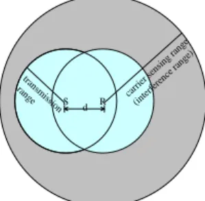
(3) capture, discard the new packet, and allow the receiving interface to continue with its current receive operation; otherwise, a collision occurs and both frames are dropped. Here the 10 dB is a usually used value in network simulator while modeling the receiver's capability to capture noise from signal. Hence, as shown in Figure 3, a collision happens when a signal propagated inside carrier sense range arrives earlier than a signal propagated inside a transmission range arrives. Because the later stronger signal collides the formal weak signal receiving. This is also an instance of large interference range.. hoc support that mobile nodes are located randomly, the situation do really exists and becomes a serious problem. To prove this fact, [7] uses a simple analytic model to show that in the open space environment, the interference range of a receiver is 1.78 times the transmitter-receiver distance as Figure 2 shows. This result overthrows the early assumption of interfering nodes are within the transmission rang. If the distance between the transmitter, S, and receiver, R, is d, then the interference range is 1.78*d, which may be larger than the transmission range. Any stations inside this interference range once transmitting to other nodes can interfere the R's reception.. tra ra nsm ng is e s. tra ra nsm ng is e sio S n. *d 78 1.. io S n. d. d. R. ge an ) g r ge sin ran n se ce er en rri fer ca nter i(. R. Figure 3: Large interferences range in NS-2 simulator.. Figure 2: Large interference range as a function of transmitter-receiver distance.. 3.3. The Influences of Large Interference Range. 3.2. The Large Interference Range in the NS-2 Simulator. The RTS/CTS handshake was proposed to solve the hidden terminal problem based on an assumption that hidden nodes are within transmission range of the receiver. With overhearing the CTS control frame, the hidden terminals near the receiver can be inhibited so that the RTS/CTS can eliminate most interferences.. There is also another thing needed to be noticed that the carrier sense wireless networks are engineered in such a way that the carrier sensing and interference range is typically larger than the range at which receivers are willing to accept a packet from that same transmitter [10]. Many researchers use the famous NS-2 network simulator from Lawrence Berkeley National Laboratory (LBNL) [11] with extensions from the MONARCH project at Carnegie Mellon [12] to estimate their proposals. These extensions include a set of mobile ad hoc network routing protocols and an implementation of BSD's ARP protocol, as well as an IEEE 802.11 MAC protocol. In the NS-2 network simulator, the interfering range (and sensing range) is larger than the communication range. It is implemented using a simple BER model that when receiving in physical layer, if the power level of the incoming frame below the carrier sense threshold, the frame is discarded as noise; if the received power level is above the carrier sense threshold but below the receive threshold, the frame is passed to the MAC layer but marked as a packet in error; otherwise, the frame is simply forwarded up to the MAC layer. In the IEEE 802.11 MAC of NS-2, when a mobile node receives a frame, if this node is receiving, one of two things can happen. If the power level of the packet already being received is at least 10 dB greater than the received power level of the new packet, the MAC layer assume. Ideally, the RTS/CTS handshake can eliminate most interference. However, if the large interference range is concerned, the RTS/CTS is not so effective; nodes located outside the transmission range of both transmitter and receiver may still interrupt reception because those nodes cannot receive the RTS/CTS correctly [7], they won't be silenced but they could cause interferences.Moreover, the large interference range will cause more collisions either on control frames or data frames, result in more serious problems such as TCP instability and unfairness [8]. This problem is infrequent in the IEEE 802.11 basic service set, because all nodes can sense each other's transmissions. However, in an ad hoc network, it becomes a serious problem due to the large distribution of mobile nodes and the multihop operation. In [7], they propose a simple MAC layer scheme called Conservative CTS Reply (CCR). An intended receiver only replies a CTS frame to a RTS initiator when the receiving power of that. -3-.
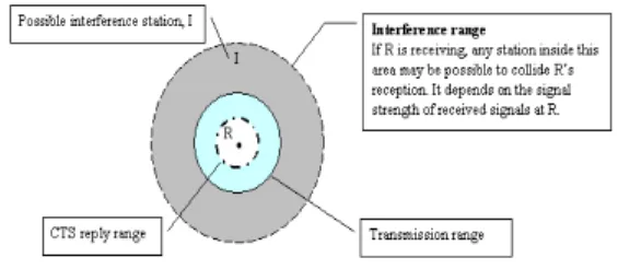
(4) RTS frame is larger than a certain threshold (CTS_REPLY_THRES-HOLD). Let Rtx denotes the transmission range. The value is chosen as a receiving power at a receiver which is 0.56*Rtx away from the transmitter. Since when the transmitter-receiver distance is smaller than 0.56*Rtx, the interference range is smaller than 1.78 * (0.56 Rtx), which is Rtx. So the whole interference area is covered by RTS/CTS handshake. Therefore can totally eliminate collisions caused by large interference range. The illustration of transmission range, interference range, and CTS reply range are shown in Figure 4, where the CTS reply range is the range of a receiver willing to reply CTS back to the RTS initiator.. a simple mechanism that dynamically adjusts the value of "CTS_REPLY_THRESHOLD" according to the historical neighboring medium usage status. If the receiver has some information about the interfering nodes’ statuses, frequency of transmissions, and interfering power strengths, the receiver may take this information to compute the CTS_REPLY_THRESHOLD, so as to predict oncoming reception interfered or not. Note here that the CCR scheme assigns the CTS reply range in Figure 4 a fixed value, 0.56*Rtx, while our goal is aimed to dynamically adapt the CTS reply range according to the channel status at receiver side. Mobile nodes periodically sense the medium status and record the sensed signal strength to compute the threshold that can present the current channel state as Figure 5 shows. Let mobile nodes sense the medium status every sense_signal_interval micro seconds, total number of sensing is sense_times. The sensed signal strength will be recorded and the oldest recorded information will not be kept if the number of sensed records exceeds sense_times. Note that we only record the sensed signal strength transmitted inside the interference range but outside the receiving range, i.e. the signal transmitted inside the gray area of Figure 4. This is because the recorded signal strength will be used to compute the CTS_REPLY_THRESHOLD, which concerns the potential transmissions that can cause interferences; the CTS control frame will silence the interferers inside the transmission range.. Figure 4: The illustration of transmission range, interference range, and CTS reply range. However, the CCR is over conservative that limits the available radio utilization range. Only transmitters inside 0.56*Rtx of receiver are allowed transmitting, which reduces the available transmission area to 31.36% of physical transmission area, even if there are no hidden terminals in the interference range, is not effective if mobile nodes are sparse or the traffic is not heavy. Therefore, we propose an Adaptive IEEE 802.11 MAC (AMAC) that makes two simple modifications of the IEEE 802.11 RTS/CTS handshake to reduce the influences of collisions resulted from large interference range.. 4. The AMAC mechanism The AMAC protocol modifies the IEEE 802.11 RTS/CTS handshake on transmitter (RTS) and receiver (CTS), respectively. In reception, we make the hardware's best to receive but estimate for the probability of successful reception to prevent from useless weak signal transmission, compared to hidden terminals' signal, being collided with nodes' transmissions near the receiver and collides other nodes’ receptions near transmitter. In transmission, not only make the most transmission opportunity but also give neighboring nodes chances to transmit or receive.. Figure 5: The periodically sense the medium. The considerations of CTS reply include two limitations. One is the estimation of whether interference will happen or not; another is the probability of interference if it happens. With the first limitation, we calculate the average of recorded signal strengths not equal to zero as equation (1), where Δ i is used to identify whether Pi is needed to be included or not; n is the sense_times; Pi is the sensed signal strength between the threshold of receiving and of carrier sensing, and the Capture_Threshold is the capability the receiver can capture noises from signals. Usually the Capture_Threshold is 10. The recorded signal strength equals to zero means that. 4.1. Receiver Side Control Mechanism Inspired from the CCR scheme, we propose. -4-.
(5) the channel is always busy or the channel is too noisy around the receiver, then the receiver will decide not to reply the CTS for a demand RTS request. Another benefit is that although the receiver may not reply a CTS back to the RTS requestor, it is still a good decision because the "weak" data transmission (in compare to the stronger interference signal strength at receiver) sent after receiving the CTS may not be received by the receiver, because of the collisions happened at receiver. On the same time, this weak data transmission could still collide other nodes' receptions near the transmitter, just as the transmitter's data collided by other nodes at receiver. So this mechanism should be beneficial to wireless ad hoc networks.. the neighboring nodes are idle or some neighboring nodes inside the receiving range is transmitting. The computation is done with every periodical sense. Hence, the CTS_REPLY_THRESHOLD could reflect locally channel status. ⎧1, carrier _ sense _ threshold < Pi ≤ receive _ threshold ∆i = ⎨ ⎩0, otherwise ⎛ n −1 ⎞ ⎜ ∑ Pi ∗ ∆ i ⎟ ⎟ ∗ Capture _ Threshold CTS _ REPLY _ THRESHOLD = ⎜ i =0n−1 ⎜ ⎟ ∆ ⎜ ∑ i ⎟ ⎝ i =0 ⎠. (1). With the second limitation, we concern about the probability of the reception be collided. We use the past recorded signal strength as limitation 1 used to roughly estimate colliding or not. This probability is obtained as equation (2), whereΔi is used to identify whether Pi larger than PRTS or not; the PRTS is the received signal strength of the RTS control frame, this PRTS is used to be compared with the CTS_REPLY_THRESHOLD to decide being collided or not. ⎧⎪1, Pi > PRTS ∆i = ⎨ ⎪⎩0 , otherwise n −1 ∑ ∆i 0 i = = p collided n. 4.2 Transmitter Side Control Mechanism As Section 2 stated, the CSMA/CA, which is a random access control mechanism, is contention-based. All mobile nodes want to transmit have to contend for the channel. Therefore, the transmissions are in a disordered manner and due to large interference range, a transmission may be collided by another transmission and collides other's transmission. There is a need to control not necessary or excessive transmission, so we propose the transmitter side control mechanism that adapts to neighborhood situations.. (2). After receiving RTS successfully, the intended receiver first checks if the power of the received RTS is larger than the computed CTS_REPLY_THRESHOLD; if larger, then he replies CTS back; if not larger, then he reply CTS with probability 1-pcollided.. Before actually sending out a control frame, the RTS, the mobile node first checks the neighbors' activities, which is gotten from the periodically sensing the receiver side does (because every transmitter is also a receiver). If their activities are less than a threshold, neighbor_tx_threshold, it might because mobile node is too loud so that they couldn't get the medium. So we let the mobile node silence for a while. Let δ i denote whether neighboring nodes transmit at ith carrier sensing or not; N is the total number of neighboring nodes' transmission activities; and neighbor_tx_ratio is defined as the portion the total number of times neighboring nodes transmit in sense_times periodically sense as equation (3) shows.. This is because collisions happen at receivers. It is better for receivers to take the responsibility for monitoring the signal statuses and to estimate admitting receptions or not. So, if a neighboring node, I, locate outside the transmission range of receiver, R, transmit frequently, any transmitter, S, once transmitting as mentioned in the standard IEEE 802.11 in Section 2, may experience a collision at R, even if the RTS/CTS handshake is presented. If R decides to only reply S when the receiving signal strength of S is higher than the calculated CTS_REPLY_THRESHOLD, the neighboring activities R saw, the problem above may less happen. On the other hand, if neighboring nodes transmit infrequently, then the CTS_REPLY_THRESHOLD should not be hold as the CCR specified; the threshold should be relaxed. This can be done by our periodical computation so as to dynamically reflect the current situation.. ⎧1, P > carrier _ sense _ threshold. i δ i = ⎨ 0 , otherwi se ⎩ n−1. N =. ∑ δi. (3). i =0. neighbor _ tx _ ratio =. This mechanism has two benefits. One is that it can adapt to surrounding channel status. If. If. -5-. N n. neighbor_tx_ratio. is. less. than. a.
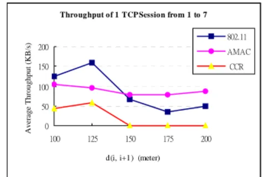
(6) neighbor_tx_threshold, and the mobile node himself sent recently, this may imply that the number of times neighboring nodes transmitted is below a certain level, it maybe resulted from neighboring nodes hardly contend for the channel so they needed to be silent because the mobile node was sending too much times. So we let the mobile node backoff to release the medium access for neighboring nodes.. the relationship between the interferences and the distance of transmitter-receiver. Each node is identical. The path loss model is set to Two-Ray Ground model; DSR routing protocol is used; the traffic generator is a greedy TCP. The topology of this simulation is a 7 nodes chain topology as shown in Figure 6.. There is also a situation needed to be concerned. If the mobile node backoff according to the policy above, we should also consider whether the neighboring nodes' silence is because of no data to send or being inhibited by the mobile node. We make a feedback of the value of neighbor_tx_threhsold. After backoff according to this transmitter control policy, mobile node observes that whether the total number of neighboring nodes' transmission activities increases or not. If do increase, it may imply the neighboring nodes have data to send out, and the mobile node should slow down the transmission. In this case, the neighbor_tx_threshold is increased. On the other hand, if the activities don't increase, it may imply that the neighboring nodes really have no data to send out, and the mobile node can speed up its transmission. In this case, the neighbor_tx_threshold is decreased.. Figure 6: The topology of 1 TCP flow simulation. The distance between any two neighboring nodes is equal, let d(i, i+1) be the distance between node i and node i+1. We adjust the distance of d(i, i+1) from 100m to 200m to observe the throughput variation. With the distance between each node increase, the number of hops increases. The simulation result is shown in Figure 7. Throughput of 1 TCP Session from 1 to 7. Average Throughput (KB/s). 802.11. In the way of both receiver side and transmitter side control, we can reduce fragile frame that the receiving signal at receiver is low or easily be collided with hidden terminals in the interference range, by not responding to CTS frame, and won't collide with other's reception if the node transmits. We can also achieve MAC level fairness in some degrees by means of our transmitter side control to give other nodes chances to transmit or to receive.. 200. AMAC CCR. 150 100 50 0 100. 125. 150. 175. 200. d(i, i+1) (meter). Figure 7: The throughput of 1 TCP session from node 1 to node 7. We can see that when d(i, i+1) is less than 125m, the throughput of IEEE 802.11 is high. This is because with such distances, the transmission from node 1 to node 7 only involve 3 hops and the most import of all, each sender, e.g. the node 1, node 3, and node 5 can sense each other's transmission, therefore can avoid most interferences. However, once the distance d(i, i+1) bigger than 125m, the throughput degrades significantly. This confirm the statements that the IEEE 802.11 was primordially designed for WLAN, was not designed for multihop ad hoc network, the IEEE 802.11 MAC cannot function well in such networks.. 5. Performance evaluation We use the NCTUns simulator [13] to justify our proposed modification of the IEEE 802.11 MAC protocol. The MAC protocol of the NCTUns is ported from NS-2 network simulator which implements the complete IEEE 802.11 standard MAC protocol DCF to accurately model the contention of nodes for the wireless medium. All nodes communicate with identical, half duplex, wireless radios that are modeled after the commercially available 802.11(b)-based Wave-Lan wireless radios, which have a bandwidth of 11 Mb/s and a nominal transmission radius of 250 meters with the carrier sensing range is 550m.. We also take a look of the CCR scheme, the throughput was not good in this scenario, it is because the CCR is over conservative that cannot reflect the neighboring nodes' situations so that they only accept the received signal strength of RTS control frame greater than Conservative CTS_REPLY_THRESHOLD. Therefore, in case of distance d(i, i+1) below 141m (250m * 0.56) do the CCR reply the CTS to the transmitter. With d(i, i+1) larger than 141m will the CCR not reply. 5.1 The Simulation of 1 TCP Flow via Multihop Transmission We first setup a simple simulation to analyze. -6-.
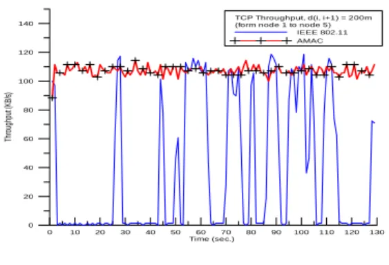
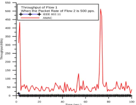
(7) CTS. Hence, no transmissions occur. So in this topology, the transmission is a 6 hops transmission when d(i, i+1) is less than 141m, this is why the throughput is low, and no transmissions happen while d(i, i+1) is greater than 141 m.. traffic is from node 1 to node 5. The simulation result is shown in Figure 9. TCP Throughput, d(i, i+1) = 200m (form node 1 to node 5) IEEE 802.11 AMAC. 140. 120. Throughput (KB/s). 100. Now, let us consider our proposed scheme, AMAC. The throughput is not good in contrary to IEEE 802.11 MAC protocol when the d(i, i+1) is l00m and 125m. This is because our control in transmitter and receiver will reduce the transmission rights. However, when the distance is larger, the performance of AMAC is better than the other two MAC protocols. This is because our scheme can decrease the probability of collisions. Let the "data frame collision ratio" as the portion of data frames transmitted at the MAC layer which are collided at the receiver due to collision; the retransmission data frame is viewed as a new data frame. We only count the data frame collision ratio of unicast data frames, thus exclude routing packets that are broadcasting based. The simulation result of data frame collision ratio is presented in Figure 8.. Data Frame Collision Ratio. 0.3. 802.11 AMAC. 0.2. 60. 40. 20. 0 0. 10. 20. 30. 40. 50. 60 70 Time (sec.). 80. 90. 100. 110. 120. 130. Figure 9: The TCP throughput. From the figure above, we can see that our proposed scheme can eliminate the TCP instability problem. The reason is that the senders controlled by our AMAC adjust their transmission rate, which can fit well with this chain multihop transmission.. 5.3 The Large Interference Range Simulation We now estimate the influences of large interference range. The simulation topology is shown in Figure 10. We let the distance d(i, i+1) 200m, except d(2, 3) is well calculated to 355 meters so that node 3 and node 1 cannot sense each other, but node 3 can interfere node 2.. Data Frame Collision Ratio of 1 TCP Session from 1 to 7. 0.25. 80. CCR. 0.15 0.1 0.05 0 100. 125. 150. 175. 200. d(i, i+1) (meter). Figure 10: The simulation topology. Figure 8: The data frame collision ratio of 1 TCP session from node 1 to node 7.. The scenario of this simulation is that node 1 sends CBR/UDP traffic to node 2 as "Flow 1", the CBR packet size is 1024 bytes and the packet rate is 500pps, node 3 sends VBR/UDP traffic to node 4 as "Flow 2", where the VBR packet size is also 1024 bytes but the packet rate is not fixed. We vary the VBR packet rate from low to high to observe the interference problem. The VBR traffic generated is Poisson distribution. We simulate the throughput degrade of node 1 to node 2 in presence of node 3's interferences.. From Figure 8, we can see that the IEEE 802.11 suffers from more serious collision than CCR and AMAC. It is also a hint that the contention manner of CSMA/CA may not suit for multihop connection. Every node constructive to compete the medium interferes other nodes. Eventually, every node interferes every node.. 5.2 The TCP Instability Problem Simulation. Once we start the transmission of Flow 2, the reception of node 1's transmission on node 2 will be interfered by node 3's transmission. The throughput of Flow 1 when the packet rate of Flow 2 is 500 pps is shown in Figure 11. From Figure 11, the throughput of IEEE 802.11 almost always 0 while the throughput of AMAC is higher than that of IEEE 802.11.. In [8], they reveal the TCP instability problem in IEEE 802.11 multihop networks. This problem is resulted from the insufficient access control of IEEE 802.11 MAC. Here we redo the same simulation as [8] stated. The simulation topology is still a chain topology as Figure 6 shown with d(i, i+1) is 200m. The parameters are also the same as section 5.2 used. The traffic generator is a TCP sender that always has data to send out. DSR routing protocol is used. The. -7-.
(8) 550. propose an adaptive MAC (AMAC) scheme by modifying the IEEE 802.11 MAC RTS/CTS handshake. We add two control mechanisms on transmitter and receiver with the objective of reducing probability of collisions and reducing the number of collisions. The simulation results show that our modification used in the multihop wireless ad hoc networks outperforms the IEEE 802.11 MAC.. Throughput of Flow 1 When the Packet Rate of Flow 2 is 500 pps.. 500. IEEE 802.11 AMAC. 450 400. Throughput (KB/s). 350 300 250 200 150 100 50 0 0. 20. 40. 60. 80. 100. Time (sec.). References. Figure 11: The throughput compare when the packet rate of node 3 is 500 pps.. [1]. Antoine Mercier, Pascale Minet, Laurent George, and Gilles Mercier, “Adequacy between multimedia application requirements and wireless protocols features,” IEEE Wireless Communications, vol.9 No.6, pp. 26-34, December 2002.. [2]. Ramiro Jordan and Chaouki T. Abdallah, “Wireless communications and networking: an overview,” IEEE Antenna's and Propagation Magazine, vol. 44 no. 1, February 2002.. [3]. IEEE, 1999, Wireless LAN Media Access Control (MAC)and Physical Layer(PHY)Specifications, IEEE Std. 802.11.. [4]. Crow, B.P.; Widjaja, I.; Kim, L.G.; Sakai, P.T., “IEEE 802.11 Wireless Local Area Networks,” IEEE Communications Magazine, Volume: 35 Issue: 9, pp.116-126, Sept. 1997.. [5]. L. Kleinrock and F. Tobagi, “Packet switching in radio channels, part II-the hidden terminal problem in carrier sense multiple access and the busy tone solution,” IEEE Trans. Commun., vol. COM-23, no. 12, pp. 1417-1433, Dec. 1975.. [6]. P. Karn, “MACA-A New Channel Access Method for Packet Radio,” in Proc. 9th ARRL Computer networking Conference, 1990.. [7]. Kaixin Xu, Mario Gerla, and Sang Bae, “How effective is the IEEE 802.11 RTS/CTS handshake in ad hoc networks?” GLOBECOM 2002 - IEEE Global Telecommunications Conference, no. 1, pp. 72-77, November 2002.. [8]. Xu, S.Saadawi, T. “Does the IEEE 802.11 MAC Protocol Work Well in Multihop Wireless Ad Hoc Networks?” IEEE Communications Magazine, Volume: 39 Issue: 6, pp. 130 -137, June 2001.. [9]. Jinyang. Li, Charles Blake, Douglas S. J. De Couto, Hu Imm Lee, and Robert Morris, “Capacity of ad-hoc wireless networks,“ Proceedings of ACM MOBICOM 01, pp. 61-69, July 2000.. [10]. Joao L. Sobrinho, A. S. Krishnakumar, “Quality-of-Service in Ad Hoc Carrier Sense Multiple Access Wireless Networks,” IEEE Journal on Selected Areas in Communications, no. 8, pp. 1353-1368, August 1999.. [11]. VINT Group, UCB/LBNL/VINT network simulator-ns (version 2), http://www.isi.edu/nsnam/ns.. [12]. The CMU Monarch Project, Wireless and mobility extension to ns, http://www.monarch.cs.cmu.edu.. [13]. S.Y. Wang, C.L. Chou, C.H. Huang, C.C. Hwang, Z.M. Yang, C.C. Chiou, and C.C. Lin, "The Design and Implementation of the NCTUns 1.0 Network Simulator", Computer Networks, Vol. 42, Issue 2, pp. 175-197, June 2003. The CMU Monarch Project, Wireless and mobility extension to ns, http://www.monarch.cs.cmu.edu.. 5.4 Random Topology Simulation In the last subsection, we simulate a random topology scenario. 100 nodes are randomly placed in a 1000m * 1000m area. DSR routing protocol is used. We randomly select 4 pairs to send UDP/CBR traffic. The packet rate is 500 pps with packet size 1024 bytes.. Average Through (KB/s). Average Through (KB/s). 80 60 40 20 0 IEEE 802.11. CCR. AMAC. Figure 12: throughput of random topology. Data Frame Corruption Ratio. Data Frame Corruption Ratio. 0.04 0.03 0.02 0.01 0 IEEEE 802.11. CCR. AMAC. Figure 13: the data frame corruption ratio. The simulation results are shown in Figure 14 and Figure 12. In the Figure 13, we can see that the throughput of AMAC is higher than the IEEE 802.11 and CCR. This is because our scheme can reduce the collisions thus improves the throughput. The CCR scheme can really eliminate the data corrupted, but the throughput is not very good because it needs more hops to reach destination. 6. Conclusion In the multihop wireless ad hoc networks, the performance of IEEE 802.11 MAC degrades dramatically. The networks suffer from more serious hidden terminal problem than the WLAN because of large interference range. In this paper we are inspired from previous analysis of [7] to. -8-.
(9)
數據
+3
相關文件
using & integrating a small range of reading strategies as appropriate in a range of texts with some degree of complexity,. Understanding, inferring and
A smaller aperture increases the range in which A smaller aperture increases the range in which the object is approximately in focus. Di
“Ad-Hoc On Demand Distance Vector Routing”, Proceedings of the IEEE Workshop on Mobile Computing Systems and Applications (WMCSA), pages 90-100, 1999.. “Ad-Hoc On Demand
• As RREP travels backwards, each node sets pointer to sending node and updates destination sequence number and timeout entry for source and destination routes.. “Ad-Hoc On
Abstract— This paper has analyzed link probability, expected node degree, expected number of links, and expected area collectively covered by a finite number of nodes in wireless ad
Kyunghwi Kim and Wonjun Lee, “MBAL: A Mobile Beacon-Assisted Localization Scheme for Wireless Sensor Networks,” The 16th IEEE International Conference on Computer Communications
Krishnamachari and V.K Prasanna, “Energy-latency tradeoffs for data gathering in wireless sensor networks,” Twenty-third Annual Joint Conference of the IEEE Computer
Selcuk Candan, ”GMP: Distributed Geographic Multicast Routing in Wireless Sensor Networks,” IEEE International Conference on Distributed Computing Systems,
