行政院國家科學委員會專題研究計畫 期中進度報告
在具有 DiffServ 的 MPLS 網路上針對多媒體資料流的減小延
遲變化機制(1/2)
計畫類別: 個別型計畫
計畫編號: NSC92-2213-E-110-028-
執行期間: 92 年 08 月 01 日至 93 年 07 月 31 日
執行單位: 國立中山大學電機工程學系(所)
計畫主持人: 許蒼嶺
計畫參與人員: 許蒼嶺 郭炳琦 謝進忠 林俊賢 江永賢
報告類型: 精簡報告
處理方式: 本計畫可公開查詢
中 華 民 國 93 年 5 月 25 日
行政院國家科學委員會專題研究計畫成果報告
在具有 DiffServ 的 MPLS 網路上針對多媒體資料流的減小延遲
變化機制(1/2)
Jitter Minimization Mechanisms for Multimedia Traffic in
DiffServ MPLS Networks (1/2)
計畫編號:NSC 92-2213-E-110-028
執行期限:92 年 8 月 1 日至 93 年 7 月 31 日
主持人:許蒼嶺 國立中山大學電機工程學系
E-mail:[email protected]
中文摘要 本 計 畫 的 目 的 在 於 結 合 Three-Color Marking 的方式來減小 DiffServ Per-Flow QoS 資 料 流 的 延 遲 變 化 , 當 量 測 封 包 提 早 抵 達 Router 時,會被放置在 Delayed-FIFO 佇列來消 除多餘的 Credits;若是量測封包延遲抵達至 Router 時,會被配置在 WRR 中最高優先權的 佇列中以降低該封包的 Deficits 來滿足端點至 端點之延遲要求。我們利用模擬的方式來驗證 本計畫所設計的演算法,實驗結果顯示較長封 包於高負載的環境下使用此機制將能顯著改 善端點至端點的延遲變化,同時也會討論 Core Router 設定不同的 Buffer 大小對於封包遺失率 與端點至端點延遲之間的關係。 關鍵詞:差別式服務網路、WRR、Credit-Deficit, TCM、Delayed-FIFO、端點至端點延遲變化 AbstractIn this project, we propose an innovative end-to-end jitter minimization mechanism with three-color marking (TCM). An early-arrival packet is assigned for a delayed-FIFO queue to consume extra credits. For late arrival packet, the highest-priority queue of weighted-round-robin (WRR) scheduling is allocated for exerting on reducing delay deficit to avoid exceeding end-to-end delay constraints. We conduct experiments by simulation and the results reveal that the proposed scheme can achieve very satisfactory end-to-end delay jitter, especially for longer-length packets under heavy traffic load. The impact of using different buffer sizes at a router to the packet loss rate and the end-to-end delay jitter is also investigated.
Keywords: DiffServ, WRR, Credit-Deficit, TCM,
Delayed-FIFO, and End-to-End Jitter.
1. Introduction
Real-time multimedia applications have been widely used in today’s Internet. Without adequate control of end-to-end jitter, the quality of multimedia presentation could be seriously degraded. To meet various QoS requirement, each packet is assumed to have an expected end-to-end delay and jitter requirements, while actual transmission delay and jitter are accumulated hop-by-hop over the network.
There are several previous works related to packet schedulers in DiffServ networks. Wang [1] adopted an adaptive-weighted packet scheduling to achieve low loss rate, low delay and jitter by dynamically changing the average queue sizes. Hsiao [2] claimed that TCP connections with receiver-based delay control works well for carrying layered video streams. However, his method can only be applied to early-arrival packets. Finally, delay jitter bounds for per-node and end-to-end nodes were investigated in [3], respectively, through mathematical models.
The main objective of this project is to control end-to-end jitter within a tolerable amount of time such that real-time traffic can meet QoS requirements. In our mechanisms, to minimizing the difference between the actual transmission delay and the expected delay requirements is through hop-by-hop adjustment cooperating with packet schedulers at intermediate routers. Three extra timestamps, representing the end-to-end delay constraints, the accumulated delay, and the average of the accumulated delay of all the previous packets, respectively, are attached to its packet header. The second timestamp is compared with the third timestamp at every router to determine whether a packet is early or late arrival. Three-color marker (TCM) is employed to represent packet arrival
status. Packets arriving at routers on time or even ahead of time are marked in green. A delayed-FIFO queue is required for the green packets to consume their extra credits. On the other hand, late-arrival packets but not exceeding the end-to-end delay constraints are marked as yellow. The yellow packets are upgraded to the highest-priority forwarding to exert on reducing their delay deficit. Packets arriving late and exceeding the end-to-end delay constraints are marked as red. The red packets are downgraded to the lowest-priority forwarding. For the purpose of evaluation, we perform experiments through NS-2 simulation. The simulation results show that the proposed mechanism can accomplish very low jitter, especially for the longer-length packets in heavy traffic load. The tradeoff of using different buffer sizes is also investigated.
2. Definition of End-to-End Jitter
Consider a real-time multimedia traffic flow traversing N hops from end to end. The expected end-to-end delay constraint, denoted as ETED, is encoded as the first timestamp in the packet optional header. As shown in Figure 1, let d(i, j) denote the experienced latency of the i-th packet at the j-th hop. We have,
( ) ( , ) ( , ) - ( , ) ( ) deq enq L i d i j T i j T i j R j = + , (1) where Tenq(i, j) and Tdeq(i, j) respectively
represent the arrival and the departure time of the
i-th packet at the j-th hop router. L(i) is the length
of the i-th packet, and R(j) is the effective data rate allocated to this traffic flow at the j-th hop router.
Let D(i, k) denote the accumulated latency of the i-th packet from the first hop to the k-th hop. We have, 1 ( , ) ( , ) k j D i k d i j = =
∑
. (2) Therefore, the accumulated end-to-end delay of the i-th packet, DETE(i), can be derived.1 ( ) ( , ) ( , ) N ETE j D i D i N d i j ETED = = =
∑
≤ . (3)Next, let davg(i, j) be the average latency of
having previously traversed i packets at the j-th hop router. davg(i, j) can be derived by applying
the Exponentially Weighted Moving Average (EWMA) algorithm. That is,
( , )=(1- ) ( -1, ) ( , )
avg avg
d i j f ×d i j + ×f d i j , (4) where f is an adjusting factor, and 0 < f < 1. Similarly, let Davg(i, k) denote the summation of
average latency of the i-th packet from the first hop to the k-th hop. We have,
1 ( , ) ( , ) k avg avg j D i k d i j = =
∑
. (5) Finally, let J(i) denote the end-to-end delay jitter of the i-th packet. The end-to-end delay jitter is defined as the absolute difference of the end-to-end delay between two consecutive packets. Hence, J(i) can be given as follows.J i( )= DETE( )i −DETE(i−1) . (6)
3. The ETEJM Algorithm
The end-to-end jitter minimization (ETEJM) algorithms employ three-color marker (TCM) to differentiate packets according to their arrival status at each router.
The summation of
average latency from the first hop to the k-th
hop can be used as a criterion to determine
whether an arriving packet is in its
early-arrival or late-arrival status.
The ETEJM algorithm with TCM is shown in Figure 2.for all i, k > 0, k < N if (D i k( , )≤Davg( , )i k )
the i-th packet is marked in green and is
pushed into delayed-FIFO or zero-delayed queue at the (k+1)-th hop;
else if (D i k( , )>Davg( , )i k and D i k( , )<ETED) the i-th packet is marked in yellow and is
re-assigned to the highest-priority queue at the (k+1)-th hop;
else if (D i k( , )>Davg( , )i k and D i k( , )≥ETED) the i-th packet is marked in red and is
re-assigned to the lowest-priority queue at the (k+1)-th hop;
Figure 2. The ETEJM algorithm with TCM
Node 1
d(i,1)
Node 2 Node 3 Node (N-1) Node N
d(i, 2) ( ) (1) L i R D(i,N-1) • • • d(i, N-1) ( ) ( 1) L i R N− • • • • • • ( , 2) ( , 2) deq enq T i −T i ( ,1) ( ,1) deq enq T i −T i ( ) (2) L i R Tdeq( ,i N− −1) Tenq( ,i N−1) Node 1 d(i,1)
Node 2 Node 3 Node (N-1) Node N
d(i, 2) ( ) (1) L i R D(i,N-1) • • • d(i, N-1) ( ) ( 1) L i R N− • • • • • • ( , 2) ( , 2) deq enq T i −T i ( ,1) ( ,1) deq enq T i −T i ( ) (2) L i R Tdeq( ,i N− −1) Tenq( ,i N−1)
Figure 1. Experienced latency of end-to-end As shown in Figure 2, the delayed-FIFO
queue is logically separated into k queues with each queue having an upper latency bound, denoted as
dupper. For the purpose of controlling the service
duration, these k FIFO queues are operated in round robin fashion. Let q(i) denote the queue length (in
bytes) of the i-th FIFO queue in each round. We have, ( ) upper , q i ≤d ×R (7) 3 R
where i = 1 to k, and R is the data rate of output link. Note that if q(i) is larger than , the i-th delayed-FIFO queue would have to deny any arriving packets, and a zero-delayed queue is assigned for serving the packet instead.
upper
d ×
Figure 3 shows the process of early-arrival packets. From (7), we know that a packet, if marked in green, would have to be purposely increased with an extra delay within the range from 0 to at each hop. Let be the difference between
D(i, k) and D upper k d× ( , ) D i k ∆
avg(i, k). That is,
∆D i k( , )=Davg( , )i k −D i k( , ). (8)
for a packet marked in green and
the m-th queue has to serve n packets with fixed length L;
( , ) avg( , ) ( , )
D i k D i k D i k
∆ = − ;
if (∆D i k( , )≥ ×k dupper and q m( − ≤1) dupper×R) assign this packet to the (m-1)-th queue;
( 1) ( , ) ( , ) upper n L q m D i k D i k k d R R × − ∆ ← ∆ − × + + ; else
index = {(∆D i k( , )mod dupper) + m} mod k; if (
q index
(
)
≤
d
upper×
R
)assign this packet to the (index)-th queue;
( , ) ( , ) ( , ) ( 1) upper upper D i k D i k D i k d d ⎢∆ ⎥ ∆ ← ∆ − ⎢ ⎥+ × ⎢ ⎥ ⎣ ⎦ ( ) n L q index R R × + + ; else
assign this packet to the zero-delayed queue;
Figure 3. The process of early-arrival packets
For a packet marked in yellow, the highest-priority queue is chosen for serving the packet. The packet queuing delay with weighted round robin (WRR) scheduler can be determined as long as the number of packets to be serviced in a round (Round(i)) for each of the k queues can be calculated as ( ) ( ) i Q i Round i W = , i = 1 to k, (9) where Q(i) and Wi are the queue length and the
WRR weight of the i-th queue, respectively. The packet is therefore assigned to a queue with the smallest Round number, which implies that the packet can insure the least queuing delay in this hop. After a sequence of adjustments hop by hop, a late-arrival packet maybe possibly meet expected
end-to-end delay constraint. The process of late-arrival packets is shown in Figure 4.
for a packet marked in yellow; for i = 1 to k ( ) ( ) i Q i Round i W = ; min( ( )) i index= Round i , i = 1 to k;
assign the packet to the (index)-th WRR queue;
Figure 4. The process of late-arrival packets
4. Results and Discussions
To evaluate the performance of the proposed ETEJM algorithms, we conduct a simulation through NS-2. The network topology is depicted in Figure 5. All links have a capacity of 100 Mbps. The weight of WRR is set to 5:3:2 for the three DiffServ classes, EF, AF, and DF. The buffer size is set to 40 packets per queue. All the traffic sources, including background traffic, are generated with constant-bit-rate UDP. For simplicity, the packet length is fixed to 1000 bytes. Random early detection (RED) is employed with the minimum threshold being set to 20 packets and the maximum threshold set to 40 packets. All the simulation results are averaged of up to 10 repeated runs. The end-to-end delay constraint (ETED) and the number of delayed-FIFO queues are set to 15 ms and 4, respectively. The upper bound of delay credit to be consumed in a delayed-FIFO queue is set to 1 ms.
E1 C1 C2 C3 C4 E2 S1 S2 R1 R2 R=100Mbps R R R R R R R R R E1 C1 C2 C3 C4 E2 S1 S2 R1 R2 R=100Mbps R R R R R R R R R
Figure 5. Topology used in simulation
The results of average end-to-end delay are plotted in Figure 6. From this figure, we can see that the AF flows of the proposed ETEJM have exhibited much lower end-to-end delay than the primitive model, particularly when the traffic load is high. When traffic congestion increases, it is better for AF traffic to upgrade their packets to EF queues, since the service rate of EF queues is assumed to be larger than that of AF queues. The cumulative distribution of average end-to-end jitter is illustrated in Figure 7. From Figure 7, with the proposed ETEJM, smaller end-to-end jitter is achieved when compared to the primitive model regardless of the traffic congestion.
Figure 6. Average end-to-end delay vs. traffic load
Figure 7. End-to-end jitter distribution
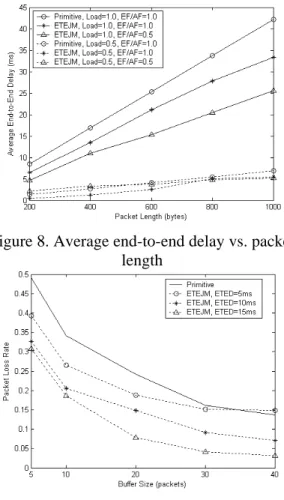
Figure 8 shows the relationship between the average end-to-end delay and the packet length. We can observe that in general the average end-to-end delay increases as the increase of the packet length. This is because larger packet lengths usually require more queuing delay at each hop. Note that when the traffic load is increased from 0.5 to 1.0, the average end-to-end delay can be substantially improved with the proposed ETEJM by dynamically upgrading packets from AF queues to EF queues.
The relationship between packet loss rate and buffer sizes is illustrated in Figure 9. The increase of buffer sizes at each router can significantly decrease the packet loss rate. Note that the curve of
ETED = 5 ms gradually decreases as the increase of
the buffer size, but it seems to slightly increase when the buffer size is equal to 40 packets. This is because at this moment more and more packets cannot meet the very tight expected end-to-end delay constraint (ETED = 5 ms) and are therefore downgraded to the DF class. Hence, the packet loss rate is increased a little bit due to the packet down-gradation from AF queues to DF queues.
Figure 8. Average end-to-end delay vs. packet length
Figure 9. Packet loss rate vs. various buffer sizes
From Figures 8 and 9, we have shown that there is a tradeoff in selecting buffer sizes at each router when the traffic load is heavy. As far as our simulation topology is concerned, the ideal buffer size tends to be 20 packets by considering two factors, the end-to-end jitter and the packet loss rate, at a time.
References
[1] H. Wang etc., “Adaptive-weighted Packet Scheduling for Premium Service,” ICC 2001, Vol. 6, Jun. 2001, pp. 1846-1850.
[2] P. H. Hsiao etc., “Streaming Video over TCP with Receiver-based Delay Control,” IEICE Trans.
Commun., Vol. E86-B, No.2, Feb. 2003, pp.
572-584.
[3] J. C. Bennett etc., “Delay Jitter Bounds and Packet Scale Rate Guarantee for Expedited Forwarding,” IEEE/ACM Trans. Netw., Vol. 10, No. 4, Aug. 2002, pp. 529-540.