~ ) Pergamon
Int. ~L Heat Mass Transfer. Copyright © 1996 Elsevier Science Ltd Vol. 39, No. 8, pp. 1697 1710, 1996 Printed in Great Britain. All rights reserved 0017 9310/96 $15.00+0.000017-9310(95)00251-0
Numerical simulation of transitional aiding
mixed convective air flow in a bottom heated
inclined rectangular duct
C. C. H U A N G t and T. F. LIN~Department of Mechanical Engineering, National Chiao Tung University, Hsinchu, Taiwan, Republic of China
(Received 18 July 1994 and in final form 27 June 1995)
Abstract--Buoyancy induced transient transitional flow structures and the associated heat transfer in mixed convective aiding flow of air in a bottom heated inclined rectangular duct were numerically inves- tigated. The three-dimensional unsteady Navie~Stokes and energy equations were discretized by higher order finite-difference approximations and directly solved by the projection method. Computations were carried out for the Reynolds number ranging from 100 to 500, aspect ratio of the duct from 2 to 4, duct inclination from 0 ° to 60°C and buoyancy-to-inertia ratio high enough to cause flow transition. Attention was particularly paid to delineate the effects of the duct inclination on the flow transition and the associated temporal and spatial flow structures. It is of interest to note from the predictions that increasing the inclined angle measured from horizontal does not always stabilize the flow. In fact, the flow stability is highly dependent on all the governing parameters and is intimately related to the structural changes in the
buoyancy induced longitudinal vortices.
1. I N T R O D U C T I O N
A simple forced convective duct flow and heat transfer in it can be significantly modified when subject to high buoyancy force. The understanding of this modi- fication of flow and thermal structures in a rectangular duct is important in various technological processes, such as cooling of microelectronic equipments, grow- ing of single crystal from chemical vapor deposition and energy transfer irt compact heat exchangers. In a mixed convective flow through a bottom heated horizontal rectangulaJr duct, the buoyancy force is normal to the forced flow direction and usually steady longitudinal vortex rolls are induced as Gr/Re 2 exceeds a certain critical value.. At a higher Gr/Re 2, the flow may become unstable and transitional. The buoyancy force, however, is no longer normal to the forced flow in an inclined duct. In fact, it can be decomposed into two components: one normal to and another parallel with the forced flow. Again, the normal component tends to induce longitudinal rolls, but the parallel component can accelerate or decelerate the flow, depending on their relative orientation to the forced flow. For aiding buoyancy the flow acceleration in the near-bottom region and deceleration in the near-top region by the para]ilel buoyancy component is expected to distort the vortices generated by the nor- mal component and tile flow can become less stable. t Dr C. C. Huang presently works at Center for Industrial Safety and Health Technology, Industrial Technology Research Institute, Hsinchu, Taiwan, Republic of China.
:~ Author to whom correspondence should be addressed.
On the other hand, the normal component is smaller for a larger inclination measured from horizontal, and hence, fewer vortices are generated and they are weaker. This produces a stabilizing effect. But when the vortices are too weak, they tend to disintegrate, which may destabilize the flow. Therefore, two opposite effects are present at the same time for an increase in duct inclination. Whether the resulting flow is stabilized or destabilized by the duct inclination depends on the particular set of parameters inves- tigated. This study intends to investigate the complex transitional vortex flow in an inclined rectangular duct under buoyancy aiding condition, through a three- dimensional time-accurate numerical simulation. Effects of the governing parameters--the inclined angle ~b, aspect ratio of the duct A and Reynolds and Grashof numbers, Re and Gr, on the flow and thermal characteristics will be examined in detail.
A considerable amount of work has been carried out in the literature to study the mixed convective flow in a horizontal plane channel. A detailed review of the early work was already given by our earlier study [1]. These previous studies are briefly reviewed here. The onset of thermal instability was experimentally and theoretically predicted [2-5]. Characteristics of the steady and unsteady vortex rolls were experimentally observed by Ostrach and Kamotani [2] and by Chiu and Rosenberger [6] and Chiu et al. [7]. More exper- imental data for the vortex flow and convective heat transfer coefficient were provided in refs. [8, 9]. Numerical simulation of the steady longitudinal vor- tex rolls was conducted by a number of studies [4, 10- 1697
1698 C.C. HUANG and T. F. LIN
NOMENCLATURE
A aspect ratio,
b/d
b, d width and height of the duct
g gravitational acceleration
Gr
modified Grashof number,g~q"d4/kv
h local convection heat transfer coefficient
k thermal conductivity
d, L dimensional and dimensionless length of the heated plate
Nu
Nusselt number,hd/k
P, p~, dimensionless and dimensional dynamic pressures,
pm/ p~ 2
Pr
Prandtl number,v/c~
q~ wall heat flux
Re
Reynolds number,%d/v
t, r dimensional and dimensionless time,
t/(d/%)
T, 0 dimensional and dimensionless temperatures,
( T - T~) / (q'~d/k )
u, v, w velocity components in x, y, z directions
U, V, W dimensionless velocity components in X, Y, Z directions,
u/#e, v)ve, w/we
x , y , z Cartesian coordinates X, Y, Z dimensionless Cartesian
coordinates,
x/d, y/d
andz/d
Z + modified Z coordinate,
Z/(Re Pr).
Greek symbols
thermal diffusivity
/3 thermal expansion coefficient
v kinematic viscosity.
Subscripts
e values at the duct inlet
fd fully developed
p period
w of wall qualities. Superscripts
- average value.
12]. Extensive studies were also performed in the past to investigate mixed convection in a vertical plane channel. A simple numerical analysis of the unidi- rectional flow at low buoyancy was given by Aung and Worku [13], Chow
et al.
[14] and Yao [15]. The buoyancy induced recirculating flow was exper- imentally visualized [16, 17] and numerically predicted [18, 19] in several studies. Effects of the channel incli- nation on the vortex flow have not received enough attention. Fukuiet al.
[20] experimentally and numeri- cally investigated a steady fully developed mixed con- vective plane channel flow withRa( = Gr x Pr)
< 9300 and 4) ~< 32.1 °. In the horizontal flow the interaction between vortices was found to be rather small. However, in the inclined flow the neighboring vortices tend to form a pair with a single velocity peak. Numerical computation from Naito and Nagano [21] investigated the buoyancy effects in the entrance region covering a wide range of inclination angle, but at subcritical Rayleigh numbers. Thus no vortex flow is formed and steady two-dimensional simulation is suitable. The critical condition for the appearance of the flow reversal was proposed. Experimental data for the local and average Nusselt number were provided by Morcoset al.
[22] and Maughan and Incropera [9]. The above literature review clearly indicates that the detailed characteristics of the buoyancy induced flow transition from steady laminar to unsteady but per- iodic laminar state and finally to unsteady irregular, turbulent state are still poorly understood, especially for an inclined duct. In an initial attempt to explore the vortex flow transition, the present authors recently conducted a three-dimensional unsteady directnumerical simulation of the mixed air convective flow in a horizontal duct of aspect ratio fixed at 2 and Reynolds number at 500 [1]. At increasing buoyancy, the flow transition was found to follow the Rulle- Taken route [23]. An extension is made here to inves- tigate the mixed convective flow transition in an inclined rectangular duct.
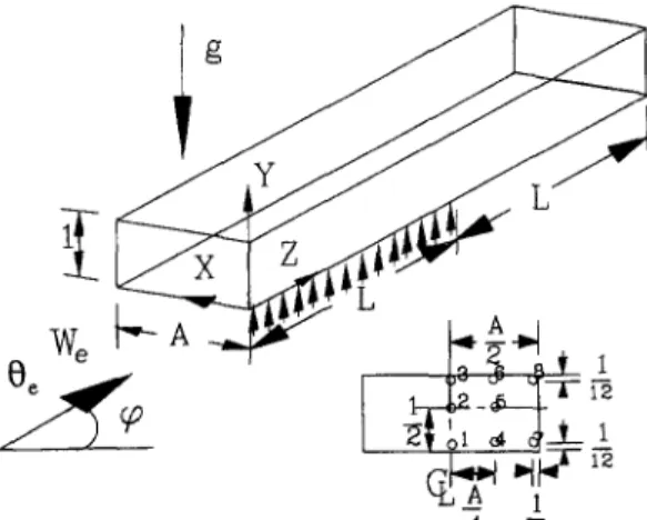
Figure 1 shows the schematic of the physical model to be investigated along with the coordinate system chosen. Initially at time t < 0, the air flow is fully developed and the isothermal at T~ in a thermally well insulated inclined rectangular duct of width b and
I
gWe b ' ~ A
Fig. 1. Schematic of the physical system and the selected detection points at a cross section (the X and Y coordinates at various points are as follows: point 1--(A/2, 1/12), 2-- (A/2, 1/2), 3--(A/2, 11/12),
4~(A/4,
1/12), 5--(A/4, 1/2),Transitional aiding mixed convective air flow 1699 height d. At t = 0, a uniform heat flux q~ is suddenly
imposed at the bottom plate over a finite length E and maintained at this level thereafter. The initially uni- directional steady flow is significantly modified as the heating level is high enough, so that the first critical Rayleigh number Ra (the onset of vortex flow) and second critical Rayleigh number (the appearance of time periodic flow) are exceeded. The evolution of these complicated flows will be carefully examined.
2. MATHEIMATICAL MODELLING
When the length, time, velocity and temperature are, respectively, scaled with the duct height d, resi- dence time of the flow d / ~ , average velocity of the forced flow ~e and conductive temperature unit q'~d/k,
the basic equations describing the temporal and spa- tial evolution of the buoyancy induced vortex flow of a Boussinesq fluid through an inclined duct studied here, are OU &V 8 W
~ 2 + ~ + ~ = 0
&U OU &U 8U OP 1 //8 2 U 8 2 U ~2 U~ -(2)
8V OV OVw~V
8-2
OP 1 (:~2V 82V 82V\ Gr = _ ~ + Re\,~X 2 + ~ + ~ ) + R e 20cOs~b8w
8w / w
W + v ~
+ ~ + -
0~
OPl{~2W
82W 82W\ Gr , 8Z ~- R e \ 8 X 2 + ~ + ~ ) + R e :Osln ~b 80 O0 &O ~z&O - - 1 T I //020 820 820X~(5)
Three governing physical parameters in the above formulation are the buoyancy-to-inertia ratio Gr/Re 2,
Reynolds number Re and Prandtl number Pr. They are defined as
G r
gflq- f]2
i~ed vRe = - - Pr = - .
Re 2 k ~ v
The problem is subject to the following initial and boundary conditions: z = O; z>~0; at U = V = O = W - W f d = O Z = 0 at Z ~ oo at Y = O and Z ~ < L 80 U = V = O = W - W f d = 0 &U &V 00 &W
- 0 &Z 8Z 0Z 8Z
~ + I = U = V = W = O &O
at all other surfaces, ~nn = U = V = W = 0, (7) where n is a unit normal to a surface and Wrd is the fully developed velocity. Based on a vast amount of experimental data, Wrd is correlated by Holes and Vermmeulen [24] as
(I)
\ m j \ n /
;]. <8,
where values of the constants m and n depend on the aspect ratio.
The local Nusselt number signifies the heat transfer from the bottom heated plate to the channel flow and is based on the difference in the bottom temperature Tw and inlet temperature T,. It is defined and evalu- ated as
hd q~ d 1
Nu = k (Tw - T~) k Ow (9)
(3) .... o
3. NUMERICAL SOLUTION
In view of the nonlinearity in the inertia terms, the basic equations were solved numerically. In particular, the projection method (Peyret and Taylor [25]) was (4) chosen here to integrate the equations on a staggered grid system. To enhance the numerical accuracy and stability, all the spatial derivatives were discretized by the fourth-order central difference (Hirsch [26]) except the convective terms which were approximated by the third-order upwind difference proposed by Kawa- mura et al. [27]. To allow for the possible asymmetric flow with respect to the central vertical plate at
X = A/2 for the time dependent flow at high buoy- ancy, the computation domain in the spanwise direc- tion includes both the left half (0 <<. X ~ A/2) and right half (A/2 <<. X <<. A) of the duct. Although the downstream boundary conditions were exactly speci- (6) fled at Z -* oo, only a finite unheated section is added in the downstream to facilitate the numerical analysis. This added unheated section must be long enough so that the solution for the problem is independent of its
1700 C.C. HUANG and T. F. LIN size. Numerical tests indicated that the suitable length
for the down-stream unheated section is L/3. To ensure the results are independent of the added section length, it is chosen to be L in the computation.
The first-order Euler explicit scheme was employed here to treat the time derivatives. We also found that the first-order scheme was sufficiently accurate to resolve the smallest physical time scale. The stability of the scheme is limited by requirement that the Cour- ant number be less than unity (Anderson et al. [28]). To ensure the numerical convergence, the Courant number is set below 0.2 in the computation, which leads to
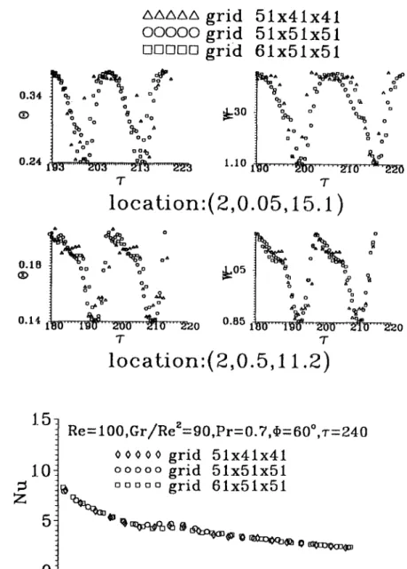
from such a test are compared in Fig. 2 for the span- wise average Nusselt number at r = 240 and time vari- ations of 0 and W at two selected locations for z between 180-220 for a typical case with Pr = 0.7,
Re = 100, Gr/Re z = 90, A = 4 and q~ = 6@'. Note that the difference in the results from using the grids 51 x41 x41 and 61 x 51x 51 is less than 3%. Thus 1, J and K were, respectively, chosen to be larger than 51, 41 and 41 in the subsequent calculation. Through these program tests, the adopted solution procedures are considered to be suitable for the present study.
4. RESULTS A N D DISCUSSION
AX AZ )
Ar < 0.2 × m i n i m u m { - - AY
~kVmax' Vma× 'W~max ' (10)
The sequence of numerical operation is as follows: (1) Explicitly calculate the provisional velocity. (2) Solve the pressure equation by the vectorized Gauss-Seidel method with successive overrelaxation. The solution for the pressure is considered as con- vergent when the mean relative pressure difference between two consecutive iterations is below 10 4. A similar criterion is employed to ensure that the mass residual is less than 10 4 at each node, at each time step.
(3) Explicitly calculate the desired velocity and temperature fields at the new time step. Procedures 1- 3 were repeatedly applied from the initiation of the transient to a final steady state or to a statistical state when the flow was no longer steady for a long time. The flow is considered at statistical state when its time- average quantities do not vary with time.
For a low Reynolds number flow considered
(Re <~ 500), a uniform grid is placed in the com- putational domain with the number of nodes in the X, Y, Z-directions--/, J and K varied from 31 to 61, depending on the particular set of parameters to be investigated.
To verify the proposal numerical scheme, a series of stringent program tests were conducted. First, the predicted spanwise average Nusselt number variations with the axial coordinate for the pure forced con- vection (Gr/Re 2 = 0) of air in a rectangular duct were found to be in excellent agreement with the numerical and experimental results of Maughan and Incropera [9]. Then, the steady mixed convection of nitrogen in a high aspect ratio horizontal rectangular duct was simulated. The comparison of the computed axial vel- ocity profiles for a typical case with Pr = 0.7,
Re = 44.8, Gr/Re 2 = 3.43 and A = 10 with the exper- imental data of Chiu et al. [7] shows good agreement [1]. Further comparison was made to test the data of Ostrach and Kamotani [2] for the spanwise tem- perature distributions. The agreement is also good. Finally, a grid test was performed. Sampled results
The above problem formulation clearly indicates that the flow to be investigated is governed by the Prandtl and Reynolds numbers, the buoyancy-to- inertia ratio Gr/Re 2, the inclination angle qS, aspect ratio of the duct A and the nondimensional length of the bottom heated plate L ( = {/d). Systematic com- putation was carried out for air flow (Pr = 0.72) in a rectangular duct of aspect ratio A = 2 and 4, inclined from horizontal by 0°~50 ° with the Reynolds number varying from 100 to 500 and L fixed at 20. The buoy- ancy-to-inertia ratio is varied from low to high values so that flow transition occurs. In the present three- dimensional unsteady flow calculation, a vast amount of numerical data were obtained. Only a very small sample of these results are to be presented here, to mainly delineate the effects of various parameters on the characteristics of mixed convective flow transition in an inclined duct. Complete results are available from our report [29]. It is noted in the computation that the predicted velocity and temperature fields are symmetric with respect to the vertical central plane at
X = A/2, except for a highly chaotic flow in which a slight flow asymmetry appears. Thus, only the results in the left or right half of the duct will be given. Attention is focused on the flow characteristics at a steady or statistical state when the initial transient has elapsed.
4.1. Effects o f the duct inclination
To illustrate the effects of the duct inclination on the flow transition, results for various inclined angles are presented for Re = 500, Gr/Re 2 = 30 and A = 2. For comparison purpose, the results for the time his- tories of the axial velocity W at selected detection points specified in Fig. 1, at three selected cross sec- tions along with the temperature contours and cross plane streamlines at various cross sections in a typical period obtained in the previous study [1] for a hori- zontal duct (q~ = 0°), are shown in Fig. 3. Note that the buoyancy induced secondary flow is in the form of two pairs of longitudinal vortex rolls (Fig. 3a). The vortex flow intensity is nonmonotonic in the axial direction and changes significantly with time, as evi- dent from the values of the streamfunctions. Also the roll size varies substantially with space and time. The time histories in Fig. 3b for W and the time records
Transitional aiding mixed convective air flow 1701 0 . 3 4 0.24 O . I B
~V
zxzxzxzxzx g r i d
O 0 0 0 Og r i d
~ o
g r i d
k
Oo o , o=aa
1:Ooo
OoO
] o 0 oO~b: I ,~o
~,,-.
I.I0
1 9 3 ... ~dD3 ...2'I3
...223
T
5 1 x 4 1 x 4 1
5 1 x 5 1 x 5 1
6 1 x 5 1 x 5 1
A o ^N :
%
o o A ° ~o a, o o ~ o o o o olg0
. . .200
. . . 2'I0... 2'27.0
T
location:(2,0.05,15.1 )
o A o o o a o o o o,,~
O. 141'80
~,~ ,,~o 0 . B 5 . . . 1 9 U ' " " 2 0 0 " " 2 " 1 0 " 2 2 0 " T o 6 o o o o m ... l ~ " z ' o o' ~ v ~ o
Tlocation:(2,0.5,11.2)
] . 5 - R e = 1 0 0 , G r / R e Z = 9 0 , P r = O . 7 , , b = 6 0 ° , ' r = 2 4 0 o 0 0 0 0 g r i d 5 1 x 4 1 x 4 1 1 . 0ooooo
g r i d 5 1 x 5 1 x 5 1 1~ o o o ~ o g r i d 6 1 x S l x 5 1iz:; 51] ~ 0 , , ~ : ~ ~ o ~ c ~ 0 q ~ , ~ o ~ ,
~
O ~ l l , l l , l l t l l l , l l l l t l [ l l l l I i i t l l l l l l l l l l l i i 1 i i i i i i 1 I0
4
8
12
16
20
Z
Fig. 2. Time histories of W and 0 at two locations and axial variations of the spanwise average Nusselt number at z = 240 calculated from various grids for P r = 0.7, R e = 100, G r / R e 2 = 90, A = 4 and ¢ = 60 °.
for 0, which are not shown here for the reason of limited space available for the article, indicate that in the entry portion of the heated section the flow oscillation is mainly characterized by a single fun- damental frequency f~ (=0.266) and its harmonics. Thus the flow is time periodic. A close inspection o f the power spectrum densities for the time histories, however, discloses that at locations 4 and 5 a second fundamental m o d e f2 (=0.320) already appears, implying that the flow around these locations is quasi- periodic. D o w n s t r e a m o f the entry portion the flow is mainly quasiperiodic. N e a r the exit end of the heated section ( Z / > 12) the flow is chaotic.
Results for ¢ = 31] ° are examined next. Figure 4
presents the secondary vortex flow patterns and iso- therms in a typical period and the time records of the axial velocity for an inclination angle o f 30 ° with other parameters fixed at the same values as those in Fig. 3. These results when contrasted with those in Fig. 3 for q5 = 0 ° suggest that at q5 = 30 ° the flow oscillates periodically at a m u c h lower single fundamental fre- q u e n c y f i = 0.09 in the entire duct. But the oscillation amplitude is higher in a n u m b e r o f detected locations for the inclined case. Besides, the intensity of the sec- ondary flow is weaker at ~b = 30 ° by comparing the streamfunction values. Furthermore, there are also two pairs of vortices in the duct at ~b = 30 °. But the vortices in the duct core are bigger and stronger than
1702 C . C . H U A N G and T. F. L1N
e:. I (.03),40"1':-.08(.03).20 8:, 1 (.03).40,1':-.06(.02). 16
e:.O(~04). 40,1,:-.08(,02). ! 3 8:.0(.04).40q:-.06(.02). 11
e:.o(.o 4).40,1,:-.09 (.02).'i ! e:.0(.04).40.1,:- .05(.01 ).09
8:.0(.04).40~,':-.08(.02).08 0:.0(.04).40",I,:-.05(.01 ).08
e:.o(.o,O.4o~,:-.oa(.o2).~ o e:.o(.o,).4o,:-.o6(.o~ ).o7
(i)
[;i!i
t . 5 ~ 1.5~::o.8
~o.~
0.0
0.0
1.5 l
~
1.5~o.a
~:~.a
0.0
0.0
1.5 I1.5
0.0
0.0
1 . 5 I 1.50.0
0.0
1 . 5 I - - 1.5~:"o.a
~="o.s
0.0
0.0
1.5 1 1.5°'3do
../.
400
04
,ww,,.,w,',wa,,w,4~,io 4oo
T 1.50.0
1.5
~="o.a
0 . 0 1.5~ . 8
0 . 0 1,5~:'-0.8
0.0
1,5
~=~o. 8
0 . 0 1.5~"0.8
0.031
10 4 0 0 T v l"+0.5"rp Z=3.23 Z=7.16 Z = 14.84 (a) (b)Fig. 3. (a) Isotherms and cross plane streamlines at cross sections (1)Z = 2.93, (2)Z = 4.88, (3)Z = 6.83, (4)Z = 8.78, (5)Z = 10.73 in a typical period, the period of the flow rp is 3.76; and (b) time histories of W at selected detection points at three cross sections (Wi denotes W at detection point i) for Re = 500,
Gr/Re= = 30, q5 = 0 ° and A = 2.
e:.o(.ot ).t a,v:-.os(.ol ).o8 e:.o(.oz).l 8,},:-.os(.oz).t 2
e:.0(.02).1 a,:-.06(.02).~ 0 e:.o(.02).~ a,:-.os(.ox).t 0
e:.o(.01 ). ~ 5,:-.0a(.02).~ 0 e:.o(.02). ~ 5 , : - . 0 s ( . 0 0 . 0 5
e:.o(.01 ).15,1,:-.08(.02).09 e:.0(.02).1 e,t,:-.08(.01 ).05
e:.o(.o I ).~ 4,~:-,04(.01 ).o4 e:.o(.01 ).14~,:-.o,K.m ).0,
v ~'+0.5~', ©1.2 0 . 6 ~ 1 . 2 0 . 6 ©i .2 0 . 6 ,=I .2 0 . 6 ,,i .2 ~ : 0 . 6
0.~
. . . 0 . 6 0 . 60.6
0.6
0 . 6 0 . 60.6
0.6
0.6
0.6
,o ,too
°'~do
,too
°'~do
400
"7" T 7"
Z=3.23 Z= 7.16 Z = 14.84
(a) (b)
Fig. 4. (a) Isotherms and cross plane streamlines at cross sections (1)Z = 2.93, (2)Z = 4.88, (3)Z = 6.83, (4)Z = 8.78, (5)Z = 10.73 in a typical period (% = 11.41) and (b) time histories of W a t selected detection
Transitional aiding mixed convective air flow 1703 those near the side walls. In summary, inclining the
duct f r o m 0 to 30 ° causes the flow to change from a transitional quasiperiodic and chaotic state to a per- iodic (more regular) state with a larger oscillation amplitude, but smaller secondary flow intensity. Thus a stabilizing effect is produced for inclining the duct from 0 to 30 °.
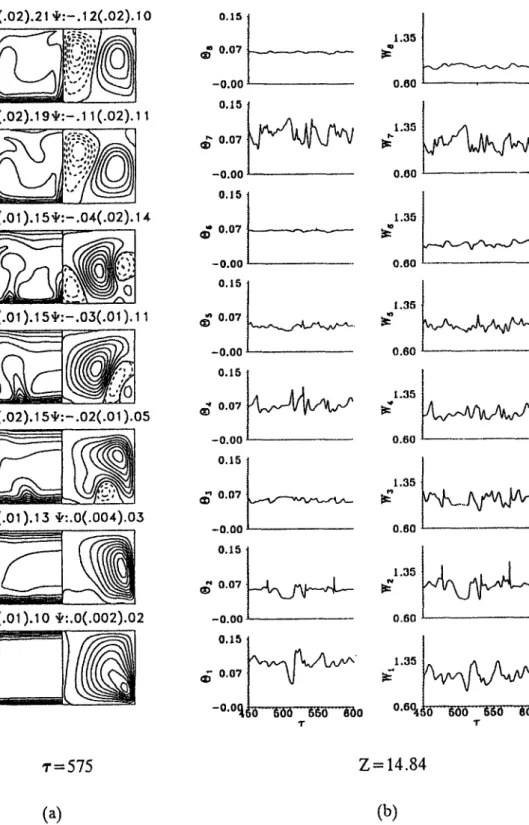
As the duct is further inclined to 45 ° , the flow becomes chaotic irL the entire duct, as evident from the time histories given in Fig. 5. N o w a destabilizing effect on the flow is produced for the duct inclining from 30 to 45 ° . In addition, the results suggest that the flow fluctuates very slowly in time, but in very large amplitude. The cause of the flow to become chaotic can be attr:ibuted to the significant change in the flow pattern for q~ = 45 °. N o t e that at q~ = 45 ° the normal buoyancy c o m p o n e n t is smaller and only a pair o f vortices are induced in the entry region. Slightly downstream, another pair of vortices are induced, sometimes near the lower corners and at other times near the central portion of the heated plate. F u r t h e r downstream, only those in the duct core grow and they gradually become stronger than the original vortices, and m a y squeeze the original pair near the side walls in the exit region. Some additional small cells are also induced near the heated plate in this region. As a result, the longitudinal vortex rolls are highly distorted and the flow is unstable. C o m - paring the streamfimction values in Fig. 5 with those in Fig. 4 manifests that the secondary flow is weaker for q~ = 45 ° only in the entry region. D o w n s t r e a m the secondary flow is stronger.
A t an even higher inclined angle o f 60 °, the flow is found to be steady in the first half o f the duct (Z ~< 10) and time periodic in the second half. The periodic flow evolution shows that only a pair of longitudinal vortex rolls are induced except in the exit region. The flow oscillation in the second half of the duct is at a lower frequency o f f , = 0.062. The oscillation amplitude is, however, not small. Thus inclining the duct from 45 to 60 ° results in a stabilizing effect on the flow.
Finally, the effects o f the duct inclination on the distributions of the heated plate temperature and local Nusselt n u m b e r are presented in Fig. 6. N o t e that in the region where the cross plane vortex flow is stronger the local Nusselt n u m b e r is higher and the plate tem- perature is lower.
4.2. Effects of the aspect ratio
Results from another series o f computations for a wider duct o f A = 4, Re = 100, Gr/Re2= 90 and q~ = 0 °, 30 ° and 60 ° are presented here to illustrate the effects o f the aspect ratio on the mixed convective flow transition in an inclined duct. The predicted results for the base case shown in Fig. 7 is the flow in a horizontal duct (~b = 0°). The time histories for W suggest that the flow in the entire duct is time periodic and is characterized by a single fundamental m o d e at f~ = 0.093 and its harmonics. It is i m p o r t a n t to note that the amplitudes o f the 0 and W oscillations are
larger in the lower half o f the duct, except in the exit region and do not always increase with the down- stream distance. M o r e precisely, the flow near the top unheated plate is nearly steady. Inspecting the time evolution of the secondary vortex flow in a period reveals that over a certain part o f the period the rolls near the side walls disintegrate at Z = 3.87, resulting in four pairs o f longitudinal rolls in the duct. The disintegration is conjectured to be caused by the additional thermals driven by the unstable thermal boundary layer on the heated b o t t o m plate. These thermals are rather weak and the rolls are found to merge later near the duct exit. It is further noted that the rolls are smaller in the vertical extent, as c o m p a r e d with those in Fig. 3 for A = 2, and only occupy the b o t t o m half o f the duct. A stable thermal stratification is resulted in the top half of the duct. This, in turn, damps the flow oscillations out and stabilizes the flow in this region, as reflected in the time histories just discussed.
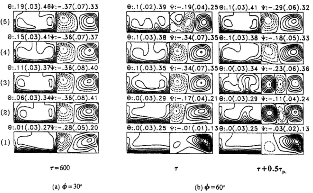
As the duct is tilted by 30 °, the flow is found to be steady at long time. It is i m p o r t a n t to note from the steady flow patterns shown in Fig. 8a that the two pairs of longitudinal rolls for ~b = 30 o are m u c h larger than those for the horizontal duct and nearly occupy the entire duct. Thus, no stable thermal stratification occurs in the upper h a l f o f the duct, as supported by the isotherms. As the duct is further tilted to 60 ° , the flow becomes time periodic again after the initial transient. Thus, there exists a reverse flow transition for raising the inclined angle for A = 4. The results indicate that at q~ = 60 °, over a certain time interval, the rolls disintegrate from two pairs to three pairs in the upstream region near the inlet and later in the downstream region near the exit o f the heated section they recombine into two pairs. Inspecting the flow patterns closely for various q~ suggests that the sec- ondary vortex flow is stronger when the duct is inclined from 0 to 30 °. But the opposite trend is noted for further inclining the duct from 30 to 60 ° . 4.3. Effects of the Reynolds number
To explore the influences o f the Reynolds n u m b e r on the flow transition in an inclined duct, results for
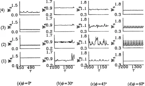
Re = 200 and 400 are examined in the following for various inclined angles. The predicted time samples of W at location 5 at various cross sections for Re = 200 are presented in Fig. 9 for various inclined angles with
Gr/Re 2 = 62.5 and A = 4. These results indicate that at ~b = 0 ° the flow is periodic in the first half of the duct and becomes quasiperiodic downstream of this region. N o n p e r i o d i c flow prevails in the entire duct at 4) = 30 °. A t ~b = 45 ° large amplitude chaotic flow is prevalent, except in the duct entry. F l o w returns to a time periodic state for q~ = 60 ° in the entire duct. The corresponding instantaneous flow patterns are given in Fig. 10 at selected time instants. The results for q5 = 0 °, when contrasted with those in Fig. 7 for
Re = 100 and ~b = 0 °, indicate that at Re = 200 the induced vortex rolls are somewhat larger, so that the
1704 e : . 0 5 ( . 0 2 ) . 2 ! , I , : - . 1 2 ( . 0 2 ) . 10 ;&~ ~,,
•
i;' - " "
e : . 0 3 ( . 0 2 ) . 1 9 , : - . 1 1 ( . 0 2 ) . 1 1 ,,,, ,,I;,(6/
' : '
e:.ol ¢ o l ).; 5 +:-.o+(.o2). 1
,+
e:.o(.o+ ).15,I,:-.o3(.o+ ). 11
e:.o(.o2). 1 s + : - . o 2 ( . o 1 ).os
(a)
e:.o(.o; ).; 3 +:.o(.oo4).os
(z)
e : . O ( . 0 1 ) . 1 0 e v : . O ( . O 0 2 ) . 0 2 C.C. H U A N G and T. F. L1N 0.15 10.07 l
-0.00 ~'0.15 {
0.15 0.07 ~ -0.000.15
0.07 -0.00 0.16,~ 0.07
-0.00 0.15 0.07 S./,,- -0.00 0.15o.o',
-0.00 0.15 ~ T 0.60I~1"35
0.001.35
0.60 1.35ff
0.60 ~1~1"35 0.601.35
f f
0.60
0.60 T"r = 575
Z = 1 4 . 8 4
(a)
(b)
Fig. 5. (a) Isotherms and cross plane streamlines at cross sections (I)Z = 0.98, (2)Z = 2.93, (3)Z = 4.88, (4)Z = 6.83, (5)Z = 8.78, (6)Z = 12.63 and (7)Z = 16.49 for • = 575 and (b) time samples of 0 and Wat
selected detection points at cross section Z = 14.87 for R e = 500, G r / R e 2 = 30, ~ = 45 ° and A = 2.
stable t h e r m a l stratification is confined in a smaller region n e a r the t o p plate. Besides, for q~ = 0 ° the struc- ture o f the l o n g i t u d i n a l rolls r e m a i n s nearly the same for the entire d u c t ( Z ~< 15), except n e a r the d u c t exit where the cell b r e a k u p occurs. I n this cell b r e a k u p
region the flow is r a t h e r u n s t a b l e . It is n o t e d f r o m the c o m p l e t e n u m e r i c a l d a t a t h a t the flow oscillates time periodically in a small a m p l i t u d e , except in the exit region where the oscillation quickly intensifies a n d b e c o m e s highly irregular, o b v i o u s l y due to the cell
Transitional aiding mixed convective air flow 1705
$ = 60 °
~ =45 °
~ o . {
~
~ o . 1 .~
,~... - ~ - , ' ~ --,,.,41/ C ' ~ ° ~ "~ =3o °
o.~ .t
@
4,__0 °
¢'~- Q . , -Fig. 6. The local Nusselt number and temperature distributions on the heated bottom plate for various inclined angles for Re = 500, Gr/Re 2 = 30 and A = 2 at large z.
disintegration. M o r e o v e r , the flow a t R e = 200 oscil- lates a t a m u c h h i g h e r frequency (f~ = 0.267), as com- p a r e d with t h a t for R e = 100 (f~ = 0.077).
F o r a d u c t tilted by 30 ° at R e = 200 the cells dis- i n t e g r a t e a n d merge in the e n t r y h a l f o f the d u c t a n d the processes r e p e a t irregularly. Besides, the sec- o n d a r y flow i n t e n s k y varies significantly with the axial distance in this region a n d is m u c h s t r o n g e r t h a n t h a t for ~b -- 0 °. In the d o w n s t r e a m the roll s t r u c t u r e does n o t experience drastic change. T h e time samples s h o w n in Fig. 9 for ~ = 30 ° do c o n c u r w i t h the a b o v e o b s e r v a t i o n . It is also o b s e r v e d t h a t the c h a o t i c flow oscillates at m u c h i)igher frequencies in regions n e a r the side walls (locations 7 a n d 8) t h a n those in o t h e r
regions. T h e decay in the oscillation a m p l i t u d e with the axial distance is clearly seen, m a i n l y in the immedi- ate d o w n s t r e a m o f the d u c t entry. It is also w o r t h m e n t i o n i n g t h a t a t ~b = 30 ° the rolls are bigger t h a n those at ~b = 0 °.
F o r a larger inclined angle o f 45 ° the flow is highly irregular. T h e b r e a k u p a n d merge o f the vortices are m o r e f r e q u e n t in b o t h time a n d space. Significant vari- a t i o n s in the vortex flow intensity are observed. T h e v o r t e x flow intensity is slightly w e a k e r t h a n t h a t for = 30 °. T h e oscillation a m p l i t u d e increases sharply with the axial distance in the e n t r y region a n d decays g r a d u a l l y in the d o w n s t r e a m . T o e n h a n c e o u r u n d e r s t a n d i n g o f the t h r e e - d i m e n s i o n a l vortex flow
1706 C . C . H U A N G and T. F. LIN
e:.+(.02).ss $:-.~ e(.03).~ se:.4(.o~).s+ t,:-.22(.03).t
e:.3(.02).56 ,t.,:-A 5(.03).136.:.3(.02).58 ,I,:-.18(.03).09
0:.2(.03).52 ,[,:-.11(.02).I I @:.2(.03).52 "I,,:-.13(.03).15 i +..~
0:.~(.0+).52 +:-.~0(.02).~ i e:.~(.o+).s2 ,:-.1 ~(.02).~+
t-: .... L, ,' --"<?ol
C
~:0.0 L. 0.0I
0,0 0 . 0 - -~:0,0 0.0 0.0 0.0<;L.-
I" "r0.0
,1.5 ~ = . . _
0.00.o - -
.,.t.5 ~
0+0 - -
"r ~'+0.5~'p Z=3.23 Z=10.97 Z= 18.70 (a) (b)Fig. 7. (a) Isotherms and secondary flow in a typical period (% = 12.99) at cross sections ( I ) Z = 3.87, (2)Z = 6.45, (3)Z = 9.02, (4)Z = 11.61, and (5)Z = 14.19 and (b) time records of W at selected detection
points at various cross sections for R e = 100, G r / R e 2 = 90, ~b = 0 ° and A = 4.
s t r u c t u r e , t h e p r e d i c t e d flow is also v i e w e d f r o m t h e side a n d top. T h e results s h o w t h e flow a c c e l e r a t i o n n e a r t h e h e a t e d b o t t o m p l a t e in t h e e n t r y r e g i o n . T h i s a c c e l e r a t e d flow is l a t e r d e f l e c t e d a w a y o r t o w a r d t h e b o t t o m plate, d e p e n d i n g o n t h e s p a n w i s e l o c a t i o n , b y t h e l o n g i t u d i n a l v o r t i c e s d r i v e n b y t h e n o r m a l b u o y - a n c y c o m p o n e n t as it p r o c e e d s d o w n s t r e a m . T h e t o p
view o f t h e flow clearly m a n i f e s t s t h e roll b r e a k u p a n d m e r g e m e n t i o n e d a b o v e . I n s p e c t i n g t h e p e r i o d i c flow e v o l u t i o n f o r q~ = 60 + a n d t h e a s s o c i a t e d t i m e r e c o r d s f o r 0 a n d W reveals t h a t t h e s t r u c t u r e o f t h e l o n g i t u d i n a l rolls c h a n g e s s u b s t a n t i a l l y s h o r t l y a f t e r t h e flow e n t e r s t h e h e a t e d s e c t i o n a n d p r o c e e d s f o r s o m e d i s t a n c e , a n d t h e flow @:. 1 9 ( . 0 3 ) . 4 6 , t , : - . 3 7 ( . 0 7 ) . 3 3
(5)
,.5.:---=....,
0:,1 5(.03).41,t,:-.3 6(.07).37
®:.1 1 (.03).37,t,.. - . 3 6 ( . 0 8 ) . + 0
@:.06(.03).3Aft':-.36(.08).41
@:.01 (.03).27,I,:-.28(.05).20
e:.l (.02).39 ,[,:-.1 9(.04).25®:.1 (.03).41 ~:-.29(.06).32
e:, 1 (.03).38 ,[,:-.34(.07).35 e:. 1 (.03).38 ,I,:-. 18(.05).33
e : . l ( . 0 3 ) . 3 S
, I , : - . 3 4 ( . 0 7 ) . 3 5 e : . 0 ( . 0 3 ) . 3 4
~I,:-.23(.06).36
0:.0(.03).29 ,r,,:-.17(.04).21 e:.0(.03).29 ,I,:-.11(.b4).24
0:.0(.03).25 ,I,:-.01 (.01).13e:.0(.03).25 ,I,:-.03(.02). i 3
,r = 600 r I" + 0.51"p.
(a) 4)=30°
(b) @=6O
Fig. 8. Isotherms and cross plane streamlines at cross sections (1)Z = 3.9, (2)Z = 6.24, (3)Z = 8.58, (4)Z = 10.92 and (5)Z = 13.26 at (a) z = 600 for q~ = 30 + and (b) in a typical period (% = 16.81) for
Transitional aiding mixed convective air flow 1707 1 . 5
(4)
0 . 0 1 . 5(3)
ff
0 . 0
1 . 5 ~
(2) f f 0 . 0 1 . 5 1 1 . 7 ~ : ' 0 . 9 0 . 2 1 . 7 0 . 2 1 . 7 0 . 2 1.8 ~ 1 . 1 0 . 3 1.8 ~ 1 . 1 0 . 3 1 . 8 0 . 3 1 . 8 0 . 3 1 . 8 ~ 1 . 8 0 . 3 0 . 3 3A&VWvVWV~ ... ... 4 9 0 0"~-2'00 1 3 0 0 0"£30'50 1 1 5 0 0"13200 1 3 0 0 T T 3" 3"(a)qb = (Y'
(b)¢ = 30 °
(c)~b = 45 °
(d)¢ =
60 ° Fig. 9. Time histories of W at location 5 at cross-sections (1)Z = 3.41, (2)Z = 7.32, (3)Z = 11.22 and(4)Z = 15.12 for ~b = 0, 30, 45 and 60 ° for Re = 200, Gr/Re ~ = 62.5 and A = 4.
in this region oscillates in a larger a m p l i t u d e (Fig. 9). Also note t h a t for ~b = 60 ° the v a r i a t i o n o f the s e c o n d a r y vortex flow intensity with the axial distance is larger t h a n t h a t for 4~ = 45°-
T o f u r t h e r illustrate the effects o f the R e y n o l d s n u m b e r o n the flow t r a n s i t i o n in a n inclined duct, results for a h i g h e r R e y n o l d s n u m b e r are e x a m i n e d in the following. T h e time histories o f 0 a n d W for
R e = 400, G r / R e z = 15.625 a n d A = 4 suggest t h a t at 4) = 0 ° the flow is time periodic in the entire c h a n n e l w i t h the decaying oscillation a m p l i t u d e in the axial direction except in tl~e d u c t e n t r y ( Z ~< 3). T h e flow is quasi-periodic in the d o w n s t r e a m h a l f o f d u c t at large for q~ = 30 °. A t ~b := 45 a n d 60 °, a steady flow pre-
vails after the initial transient. T h e c o r r e s p o n d i n g i n s t a n t a n e o u s cross p l a n e s e c o n d a r y flow p a t t e r n s a n d i s o t h e r m s at large z in selected cross sections for q~ = 0, 30, 45 a n d 60 ° are s h o w n in Fig. 11. N o t e t h a t for ~b = 0 ° in the d u c t entry, four pairs o f l o n g i t u d i n a l rolls merge into two a n d in the d o w n s t r e a m the flow s t r u c t u r e a n d s e c o n d a r y flow intensity v a r y only slightly with the d o w n s t r e a m distance. As a result, the flow oscillates in a larger a m p l i t u d e in the d u c t e n t r y a n d t h e n decays w i t h the axial distance, as j u s t m e n - tioned. N o t e t h a t n e a r the d u c t exit the flow is nearly a t steady state.
As the d u c t is inclined by 30 ° the flow b e c o m e s highly irregular, except in the d u c t entry. T h e cells are
e:.2(.02).40 i,:-.13(.03).20
e..2(.o2).4o,:-.11(.o3).19
e:.1(.o3).4o,I,:-.~ 1(.o3).1 s
e:.~ (.o3).4o,t,:-.11(.o3).~ 9
0:.o(.o4).4o ,I,:-. ~ 1 (.o3). 1 s
e:.1(.02).31 ",I':-.28(.08).33 e'..1 (.02).29 ,t,:-.28(.08).31 0:.0(.02).25 "t,:-.25(.04). 16 0:.0(.02).23 ,i,:-.27(.05).27 e:.0(.02).21 ,I,:- J 9(.0,*).23 e:. 1 (.02).29 ~:-.26(.05).27 G:.0(.02).27,t,:-.25(.05).26 0:.0(.02).26'I,:-.26(.05).26 e:.o(.o2).24,:-.12(.o5).I 8
NsN
0:.0(.02).20 ¢Z:-.O I (.01). 1 I e:.o(.o3).3o~,:-.2~,(.o6).32 0:.0(.03).28 ~z:-.10(.04)360:.0(.02).24,[,:-.18(.03).I 5
@:.0(.02).21 ~:-.05(.02)J 1 e:.0(.02). 20 ,:-.01 (.01 ).07 1"=900 "r= 1200 r = 1200 -r= 1050 (a)4~=O ° (b) ~ = 3 0 ~ (c) 05=45 ° (d) @ = 6 0 °Fig. 10. Isotherms and cross plane streamlines at cross sections (1)Z = 2.93, (2)Z = 4.88, (3)Z = 6.83, (4)Z = 8.78 alad (5)Z = 10.73 for (a) q~ = 0 °, T = 900, (b) q~ = 30 °, z = 1200, (c) ~ = 45 °, z = 1200,
1708 C . C . H U A N G a n d T. F. L I N O:, 1 (.02).33 'I':-.! 2(.04).29 0:.1(.03).31 ,I,:-.12(.04).27 e:.o(.o2).28 4,:-.14(.04).21 0:.0(.02).26,1,:-. 16(.03).I 8
,,,
e:.o(.o3).28 ~,:-.14(.03). 15e:.o(.o2). ~ 9 + : - .
0s(.o~
).o6e:.o(.o2).2o,~:-.o~(.o2).16
e:.0(.02).22 ,t,:-. 17(.03). 17
e:.o(.02). 22 ,t,:-.08(.02). 10
e:.o(.o2).22 ,t,:-.o 2(.o 1 ).09
e::.o(.o2).2o ,[,:-.o 1 (.01).06 e:.O(.02 ). 18 't':-.02(.01 ).04 e:.o(.o2).24 ~ : - . o 1 ( . o l ) . o 8 0:.o(.o2).23 , : - . m ( . o l ) . o 8 0:.0(.02).23 ~ : - . 0 1 ( . 0 1 ) . 0 8 e:.o(.o2).2o ,t,:-.oi(.ol).o8 o:.o(.oz).lS , : - . 0 1 ( . 0 t ) . 0 8 0:.0(.02).17 , : - . 0 1 ( . 0 1 ) . 0 8 e:.0(.02).2~. ,~:.00(.01 ).09 0:.0(.02).23 ,l,:.oo(.m ).08 0:.0(.02).23 ,[,:.00(.01 ).07 0:.0(.02).20 ~:.0o(.00.06 0:.0(.02).18 't':.00(.00).05 e:.0(.02).17 '1':.00(.00).03 1-=600 "r=750 ~-=600 ~-=600 (a)a~=0 ° (b) ~ = 3 0 ° (e) q~=45 ° (d) 6=60" Fig. 11. I s o t h e r m s a n d cross p l a n e s t r e a m l i n e s at cross sections (1) Z = 0.98, (2) Z = 2.93, (3) Z = 4.88, (4) Z = 6.83, (5) Z = 8.78 a n d (6) Z = 10.73 for (a) 0 = 0°, r = 600, (b) ~b = 30 ° , z = 750, (c) 4) = 45 ~, = 600, (d) 4) = 60 °, ~ = 600 for Re = 400, Gr/Re 2 = 15.625 a n d A = 4. T a b l e 1. T h e o v e r a l l flow c h a r a c t e r i s t i c s a t large
Zo"nset
Z~
f,,A
A Pr Re Gr/Re 2 q5 F l o w r e g i o n ( × 103) ( x 103) ( l / z ) Pair" 2 0.72 500 30 0 0 ~< Z ~< 2.4 SS b 5.56 6.7 f l = 0.266 2 2.4 ~< Z ~< 7.1 PC f2 = 0.320 7.1 ~< Z ~< 20 C d 30 0 ~< Z ~< 2.5 SS 9.72 6.94 f~ = 0.088 2 ~ 3 2.5 ~ < Z ~ < 2 0 P 45 0 ~ < Z ~ < 2 . 9 3 SS 12.2 8.13 - - 2 ~ 3 2.93 ~< Z ~< 20 C 60 0 ~ < Z ~ < 11.2 SS 23 31.17 f~ = 0 . 0 9 2 2 11.2 ~<Z~< 20 P 4 0.72 100 90 0 0 ~< Z ~< 3 SS 45.8 41.67 f~ = 0.077 2 ~ 4 3 ~ < Z ~ < 2 0 P 30 0 ~< Z ~< 20 SS - - - - 2 60 0 ~< Z ~< 3.41 SS - - 47.36 fL = 0.059 2 ~ 3 3.4 ~ Z ~< 20 P 4 0.72 200 62.5 0 0 ~< Z ~< 10.97 SS 13.2 17.4 J; = 0.267 2 ~ 4 10.97 ~< Z ~< 14.84 P 14.84 ~< Z ~< 20 Q W + C 45 0 ~< Z ~< 2.93 SS 30.6 - - - - 2 ~ 4 2.93 ~< Z ~< 20 Q P + C 60 0 ~< z ~< 2.93 s s 37.5 20 f l = 0.087 2 ~ 3 2.93 ~< z ~< 20 P 4 0.72 400 15.625 30 0 ~< Z ~< 3.41 SS 14.9 11.8 - - 2 ~ 3 3.41 ~< Z ~< 15.12 P 15.12 ~< Z ~< 20 Q P + C 45 0 ~< Z ~< 20 SS - - - - 2 60 0 ~< Z ~< 20 SS - - - - 2 a N u m b e r o f v o r t e x pair(s). b S t e a d y state. c P e r i o d i c a l state. C h a o t i c state. ° Q u a s i - p e r i o d i c a l state.Transitional aiding mixed convective air flow 1709 r a t h e r u n s t a b l e a n d t h e i r s t r u c t u r e s c h a n g e irregularly
with time a n d space. T h e p o w e r s p e c t r u m densities for the time records o f 0 a n d W indicate t h a t small a m p l i t u d e periodic flow oscillation prevails in the d u c t entry. Its frequency is lower t h a n t h a t for ~b = 0 °. Slightly d o w n s t r e a m , the flow oscillates in a large a m p l i t u d e with the flow b e i n g periodic in the d u c t core region n e a r the central vertical p l a n e at X = .4/2.
But elsewhere it is n o n p e r i o d i c . N e a r the d u c t exit the flow is entirely n o n p e r i o d i c .
T h e steady flow p a t t e r n s h o w n in Fig. 11 for ~b = 45 ° indicates t h a t only one pair o f l o n g i t u d i n a l rolls is i n d u c e d in the duct. The associated time rec- ords o f 0 a n d W a t v a r i o u s detection p o i n t s m a n i f e s t t h a t the initial tran,;ient is very short. A t a n even h i g h e r inclined angle o f 60 °, the resulting flow is also at steady state. T h e flow p a t t e r n is similar to t h a t for q~ = 45 °.
5. CONCLUDING REMARKS
The a b o v e results clearly suggest t h a t the d u c t incli- n a t i o n has very c o m p l e x effects o n the b u o y a n c y i n d u c e d flow t r a n s i t i o n in mixed convective air flows. T h e flow t r a n s i t i o n at v a r i o u s inclined angles d e p e n d s largely o n the R e y n o l d s n u m b e r a n d aspect r a t i o o f the duct. S o m e t i m e s the flow is stabilized by increasing the aiding b u o y a n c y . O t h e r times the reverse is the case. T h e s y m m e t r y b r e a k i n g processes are n o t sig- nificant in the flow, even if it is in a chaotic state. T o p r o v i d e a n overall picture for the flow t r a n s i t i o n in a n inclined duct, the maj or flow characteristics discussed a b o v e are s u m m a r i z e d in T a b l e 1.
Acknowledgements--The financial support of this study by
the engineering division of Nation Science Council of Taiwan, R.O.C. througl~ the contract NSC83-0404-E009-054 is greatly appreciated. The support of the present com- putation by the National Center for High-performance Com- puting and by the computer center of the National Chiao Tung University, Taiwan, Republic of China is also acknowl- edged.
REFERENCES
1. C. C. Huang and T. F. Lin, Buoyancy induced flow transition in mixed convective flow of air through a bottom heated horizontal duct, Int. J. Heat Mass Trans- fer 37, 1235-1255 (1994).
2. S. Ostrach and Y. Kamotani, Heat transfer aug- mentation in laminar fully developed channel flow by means of heating from below, J. Heat Transfer 97, 220- 225 (1975).
3. G. J. Hwang and C. L. Liu, An experimental study of convective instability in the thermal entrance region of a horizontal parallel-plate channel heated from below,
Can. J. Chem. Engn~7 54, 521-525 (1976).
4. K. C. Cheng and G. J. Hwang, Numerical solution for combined free and forced laminar convection in hori- zontal rectangular channels, J. Heat Transfer 91, 59-66 (1969).
5. F. S. Lee and G. J. Hwang, Transient analysis on the
onset of thermal instability in the thermal entrance region of a horizontal parallel plate channel, J. Heat
Transfer 113, 363-370 (1991).
6. K. C. Chiu and F. Rosenberger, Mixed convection between horizontal p l a t e s I I . Entrance effects, Int. J.
Heat Mass Transfer 30, 1645-1654 (1987).
7. K. C. Chiu, J. Ouazzani and F. Rosenberger, Mixed convection between horizontal plates--II. Fully developed flow, Int. J. Heat Transfer 30, 1655-1662 (1987).
8. D. G. Osborne and F. P. Incropera, Laminar, mixed convection heat transfer for flow between horizontal par- allel plates with asymmetric heating, Int. J. Heat Mass
Transfer 28, 207-217 (1985).
9. J. R. Maughan and F. P. Incropera, Experiments on mixed convection heat transfer for airflow in a horizontal and inclined channel, Int. J. Heat Transfer 30, 1307-
1318 (1987).
10. F. C. Chou and G. J. Hwang, Vorticity-velocity method for the Graetz problem and the effect of natural con- vection in a horizontal rectangular channel with uniform wall heat flux, J. Heat Transfer 109, 704-710 (1987). 11. F. P. Incropera and J. A. Schutt, Numerical simulation
of laminar mixed convection in the entrance region of horizontal rectangular ducts, Numer. Heat Transfer 8,
707-729 (1985).
12. H. V. Mahaney, F. P. Incropera and S. Ramadhyani, Development of laminar mixed convection flow in a horizontal rectangular duct with uniform bottom heat- ing, Numer. Heat Transfer 12, 137-155 (1987). 13. W. Aung and G. Worku, Mixed convection in ducts with
asymmetric wall heat flux, J.Heat Transfer 109, 947-951 (1987).
14. L. C. Chow, S. R. Husain and A. Campo, Effects of free convection and axial conduction on forced convection heat transfer inside a vertical channel at low Peclet num- bers, J. Heat Transfer 106, 297-303 (1984).
15, L. S. Yao, Free and forced convection in the entry region of a heated vertical channel, Int. J. Heat Mass Transfer
26, 65 72 (1983).
16, B. R. Morton, D. B. Ingham, D. J. Keen and P. J. Heggs, Recirculating combined convection in laminar pipe flow,
J. Heat Transfer 111, 106-113 (1989).
17. D. B. Ingham, D. J. Heggs and B. R. Morton, Recir- culating pipe flows, J. Fluid Mech. 213, 443-464 (1990). 18. W. Aung and G. Worku, Theory of fully developed
combined convection including flow reversal, J. Heat
Transfer 108, 485-488 (1986).
19. D. B. Ingham, D. J. Keen and P. J. Hegges, Two-dimen- sional combined convection in vertical parallel plate ducts, including situations of flow reversal, Int. J. Numer.
Meth. Engn 9 26, 1645-1664 (1988).
20. K. Fukui, M. Nakajima and H. Ueda, The longitudinal vortex and its effects on the transport processes in com- bined free and force laminar convection between hori- zontal and inclined parallel plates, Int. J. Heat Mass
Transfer 26, 109 120 (1983).
21. E. Naito and Y. Nagano, The effect of buoyancy on downward and upward laminar-flow convection in the entrance region between inclined parallel plates, Int. J.
Heat Mass Transfer 32, 811-823 (1989).
22. S. M. Morcos, M. M. Hilal, M. M. Kamel and M. S. Soliman, Experimental investigation of mixed laminar convection in the entrance region of inclined rectangular channels, Int. J. Heat Mass Transfer 108, 574-579 (1986).
23. J. Argyris, G. Faust and M. Haase, An adventure in chaos, Comput. Meth. Appl. Mech. Enyn# 91, 997-1091 (1991).
24. D. B. Holes and J. R. Vermmeulen, Velocity profiles in ducts with rectangular cross sections, Chem. Enyn# Sei.
23, 717-722 (1968).
25. R. Peyret and T. D. Taylor, Computational Methods For
1710 C.C. H U A N G and T. F. LIN 26. D. C. Hirsch, Numerical computation of internal and
external flow, Vol. 1, pp. 176-179. Wiley, New York (1989).
27. T. Kawamura, H. Takami and K. Kuwahara, New higher-order upwind scheme for incompressible Navie~Stokes equations, 9th ICNMFD 10, 285-291 (1985).
28. D. A. Anderson, J. C. Tannehill and R. H. Pletcher,
Computational Fluid Mechanics and Heat Transfer, pp.
71-77. Hemisphere, Washington DC (1984).
29. T. F. Lin, Thermal control ofmicroelectronic equipment D buoyancy driven unsteady mixed convection in rec- tangular channel (ll) NSC 81-0404-009-101, Hsinchu, Taiwan, Republic of China (1982).