FAULT TOLERANT CROSSCONNECT AND WAVELENGTH ROUTING
IN ALL-OPTICAL NETWORKS
Chuan-Ching Sue, Sy-Yen Kuo*
Department
of
Electrical Engineering Taipei, Taiwansykuo @
cc. ee.
ntu.edu. tw , NationalTaiwan
UniversityABSTRACT
This paper proposes a fault tolerant design of optical crossconnect (FTOXC) which can tolerate link, channel, and internal optical switch failures at the cost of spare optical switcheskhannels, extra input/output (VO) ports
for an optical switch, and associated wavelength convert- ers. Failure restoration is based on a unified restoration scheme and a fault tolerant wavelength routing algorithm (RWRA). The FTOXC and FI’WRA can be applied to any all-optical network and can recover many types of failures. The tradeoff is between the number of spares and the blocking probability.
I. INTRODUCTION
For a wavelength routed all-optical network (WRAON) [l], network failures could interrupt a large number of communication sessions in progress, such as voice and data transmissions. As a result, the design of a WRAON must incorporate some mechanisms of protection against certain types of failures, for instance node failures, link failures, channel failures, wavelength converter failures, and optical switch failures. It is also desirable that these failures be handled within the optical network, rather than in higher layers.
* Acknowledgment: This research was supported by the National Science Council, Taiwan, R.O.C., under Grant NSC 88-2213-E-
002-040. Sy-Yen Kuo is currently a visiting researcher at AT&T Labs-Research, Florham Park, New Jersey, USA.
Yennun Huang
AT&T Labs
-
Research Florham Park, NJ 07932USA
In order to achieve protection against failures, spares must be provided for the corrupted traffic while being restored. With the advent of WDM techniques, it is possible to provide redundancy by means of spare wavelengths. Several simple failure restoration techniques for WDM mesh networks have been proposed in [2-5,9]. In [9], they concluded that the use of spare wavelengths is better in terms of the total number of fibers.
Therefore, in this paper we will propose a fault-tolerant optical crossconnect (OXC) architecture and the corre- sponding wavelength routing algorithm subject to the current technology constraints. The fault-tolerant OXC (FTOXC), which can be utilized as a normal OXC with converters rather than only in the fault-tolerant environ- ment, was built from the combination of OXCs with and without conversion as shown in [I]. In addition, a fault- tolerant wavelength routing algorithm (FTWRA) is also proposed which is a quasi-distributed dynamic routing scheme similar to [6]. The controller in each OXC com- municates with other controllers by an in-band wave- length within the network for collecting information from the network and for finding the best routes.
The rest of this paper is organized as follows. Section I1 introduces the basic architecture of the FTOXC in a WRAON. Section I11 identifies different fault scenarios and proposes the corresponding failure restoration schemes. Section IV proposes the FTWRA algorithm. Section V concludes this paper.
1438,
0-7803-5796-5/99/$10.00 0 1999 IEEE
as two connections do not use the same wavelength on a
single link. This can be achieved in principle by using wavelength converters in conjunction with a large switch inside an OXC as shown in Fig. 3. This configuration adds significant complexity to the OXC but should yield somewhat better wavelength reuse, thereby improving the network performance. The OXC now has a single wave- length-independent switch with A.A inputs and A-A out- puts as compared to A wavelength-dependent switches each with A inputs and A outputs for an OXC without converters. In addition, A.A wavelength converters are required.
Wavelength Demux Wavelength Mux hl-hA
11. ARCHITECTURE
Fig. 1 shows a WDM all-optical network employing wavelength routing, which consists of OXCs intercon- nected by optical links. Each link is assumed to be bidi- rectional and actually consists of a pair of unidirectional links.
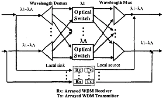
If there are A wavelengths on each link, an OXC can be viewed as consisting of A independent switches, one for each wavelength as shown in Fig. 2. Each optical switch has A inputs and A outputs where A is the number of in- putloutput links.
... + lightpath with hl
o-
- -
-b lightpath with hl and h2 Vphysical fiber link Fig. 1: A WDM network with OXCs interconnected by fiber links.
Rx: Arrayed WDM Receiver Tx: Arrayed WDM Transmitter
Fig. 2: Structure of an OXC without wavelength converters.
If we are allowed to use wavelength converters, a signal at a particular wavelength on an input link can be converted to any other wavelength on any of the output links as long
I
I
Switch/.
: Arrayed WDM Receiver
: Arrayed WDM Transmitter :Wavelength converter
Fig. 3: Structure of an OXC with wavelength converters. An arrayed multi-wavelength transmitter and an arrayed multi-wavelength receiver are required for either OXC structure in the above. Although sharing array transceiv- ers with other links could reduce the amount of hardware required [l], such structure imposes an additional con- straint on the wavelength assignment problem in that two connections originating from a given node must be as- signed different wavelengths. Apparently this reduces the probability of reuse of wavelengths.
We propose an FTOXC in Fig. 4, which has a better net- work performance and can survive a single fault. The main modifications are on the optical switches and the wavelength converters. The FTOXC utilizes the wave- length-dependent optical switches in an OXC without converters. And each optical switch is extended with additional ports and corresponding wavelength converters to connect to other optical switches. The resulting FTOXC has A optical switches with (A+A-1) inputs and
I
Rx: Arrayed WDM Receiver
: Arrayed WDM Transmiller :Wavelenglh converter
Fig. 4: Structure of an FTOXC.
(A+A-I) outputs as compared to A inputs and A outputs in Fig. 2, and A(A-1) converters as compared to A.A con- verters in Fig. 3. Completely optical methods for imple- menting the FTOXC can be easily achieved.
111. FAILURE SCENARIOS AND FAILURE
RESTORATION
Assume that the fault detection mechanism in [8] is adopted in the proposed FTOXC. We present how FTOXCs configure to deal with the fault scenarios men- tioned above.
A. Channel faults
The restoration scheme is shown in Fig. 5.
B
A
S :
'B
...
+ Restored lightpath Optical link L Original lightpath+ Failed channel
Fig. 5: Restoration from a single channel fault using a spare channel.
Let the channels C and C' be normal working channels
and the channel S a spare channel. Upon detection of
channel C failure in the link L, the controller in FTOXC
node A configures the optical switch C to transfer the lightpath to the optical switch S and configures optical switch S to transfer the lightpath to the original link L. At the other end, FTOXC B configures the optical switch S to transfer the lightpath to the optical switch C' and config- ures the optical switch C' to transfer the lightpath from
the optical switch S to the original channel.
B.
Link
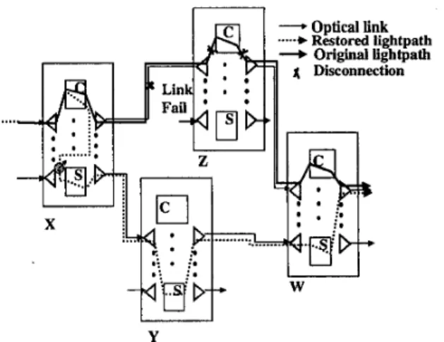
faultTake for example the lightpath in Fig. 6. The original normal lightpath is from the source node to
X,
then to 2 ,then to W, and finally to the destination node. Assume
there is a link fault between nodes
X
and Z. After de- tecting the failure, this lightpath must be able to reroute around the failed link. In our restoration mechanism, the controller in nodeX
configures the optical switch C to reroute the failed lightpath to the spare optical switchkhannelS
and keep the spare channel S to the des- tination node. How the nodesY,
W, and the nodes alongthe way to the destination know when to configure their spare optical switches is achieved by the coordination with node X . At the other end, the controller in node Z
simply disconnects the failed lightpath.
1 Disconnection
...
Fig. 6: Restoration from a link fault using a spare channel.
C. Optical switch fault
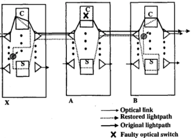
In Fig. 7 , if the optical switch C within node A fails, node
A informs the predecessor node X to redirect the lightpath to a spare channel and informs the successor node B to
receive the lightpath from the spare channel and continue the original lightpath route.
X A B
-
Optical link...+
Restored lightpathd Original lightpath )( Faulty optical switch
Fig. 7: Restoration from an optical switch fault.
D.
Wavelength converter faultThis converter D fault is a dual of the channel D fault between link A to
B.
A B
-Optical link
...+
Restored LightpathOriginal lightpath Faulty wavelength converter
Fig. 8: Restoration from a wavelength converter fault.
E. F'TOXC node fault
Due to the high cost, a spare node for fault tolerance is not recommended. Instead, we employ the idea in [7] that a node fault only affect the controller and the established lightpath can continue transfemng data. When the neigh- boring nodes complete coordination, the whole network is updated with the deletion of the faulty node and its asso- ciated links.
IV. FAULT
TOLERANT
WAVELENGTH
ROUTING ALGORITHM
We first present the FTWRA for normal routing in the following orders: graph transformation, routing, con- nect/disconnect, and overall flow chart.
A. Graph Transformation: Construct a weighted direct-
ed graph G(V, E ) from the given network G(N, L) and the
set of wavelengths A, where V is the set of vertices and E
is the set of directed edges each with weight c: E+ R.
The weight of a channel edge depends on its status. An
idle channel has a weight c(1, h) = f , and an occupied channel edge or a spare channel edge has a weight c(1, h)
= W. Similarly, the weight of a converter (normal) edge is
determined by the same rule. An idle converter (normal) edge should have weight c ( l m ,
A,,
l,,A,)
= gfJ
if h, orh,
is not a spare channel, and a converter edge has weight c ( l m , h,, I,,
A,)
= 00 if a connection converts its wave-length h, on 1, to h, on l,, or if h, or h, is the designated spare channel. The values off and g can make the routing decision toward wavelength continuous path or wave- length convertible path.
B.
Routing: Given the weighted graph G(V, E ) and a callrequest with super source-to-destination vertex pair w,
routing is to find the min-cost path corresponding to the route and the channels in the original network. Let
P,
be the set of all paths connecting w. S,, = 1 if edge e is on the path p , and S,, = 0 otherwise. Assume that the integer vector Xis the routing decision in which xp = 1 means that the new call is routed on path p and x p = 0 otherwise. Suppose that the objective is to minimize the costC x c ( e ) 6 , , x p
.
Then the problem is defined as I=P,=Efollows:
X P € IO, 11, ' d P € pw.
Using any shortest-path algorithm, e.g., Dijkstra's algo- rithm, the above problem can be solved.
C. Connect
andDisconnect:
The network status needsto be updated whenever a call is connected or discon- nected. The algorithm is as follows:
routed all-optical networks. In addition to the introduc- tion of a fault model and the corresponding restoration mechanism, a fault tolerant wavelength routing algorithm a. Connect: if a new call is routed through the chan-
nelhormal edge e, c(e) t OQ. If a new call is routed
through the converter edge e at node i, c(e) t OQ.
with dynamic spares was also proposed. This paper con- centrates on the introduction and discussion of the pro- posed mechanism. The detail analysis and evaluation are left as future works. That is, the blocking probability
The overall algorithm is shown in Fig. 9.
Graph Transformation
+
Detect Connection and
1
Rej,ectI I
Accept and set up the connectionI
I
Disco:nectI
I
I I
Fig. 9: The FI‘WRA algorithm.
When the restoration mechanism is being executed and needs the node to reestablish the route, the edges in the auxiliary graph require some modifications to find the spare route. The modifications are that the weights of unoccupied edges for the spare channels are reduced from infinite to zero and those of the occupied ones remain infinite. After such modifications, the restoration route will consist of spare channels only.
V.
CONCLUSIONS
We have proposed in this paper a fault tolerant optical crossconnect node architecture to support wavelength
VI. REFERENCES
[ l ] R. Ramaswami, and K. N. Sivarajan, “Routing and Wavelength Assignment in All-Optical Networks,”
IEEE/ACM Trans. on Networking, 1995.
[2] L. Wuttisittikulkij and M. J. O’Mahony, “Use of Spare Wavelengths for Traffic Restoration in Multi- wavelength Transport Network,” in Proc. Globe- corn ’96, pp. 1778-1782. 1996.
[3] M. Garnot, M. Sotom, and F. Masetti, “Routing Strategies for Optical Paths in WDM Networks,” in
Proc. Globecorn ’97, pp. 422-426, 1997.
[4] J. Armitage, et al., “Design of a Survivable WDM Photonic Network,” in Pmc. Infocorn’ 97, pp. 244-
252,1997.
[5] S . Okamoto, et al., “Network Protection and OA&M
mechanism for WDM Optical Path Transport Net-
works,” in Pmc. ICC ’98.
K. Lee and 0. K. Li, “A Wavelength-Convertible Optical Network,” IEEE J. Lightwave Technol., vol.
11, no. 5/6, pp. 962-970, May/June 1993.
R. Ramaswami and A. Segall, “Distributed Network Control for Wavelength Routted Optical Networks,” in Pmc. Infocorn ’96, 1996.
[8] C. Li and R. Ramaswami, “Automatic Fault Detec- tion, Isolation, and Recovery in Transparent All- Optical Networks,” ZEEE J. Lightwave Technol., vol. 15, no. 10, pp. 1784-1793, Oct. 1997.
S. Kuroyanagi and T. Nishi, “Optical Path Restora- tion Schemes and Cross-Connect Architectures for Photonic Transport Networks,” in Proc. Globe- corn ’98.
[6]
[7]
[9]