可調適無線電連線品質之
移動式隨意網路繞徑協定
A Radio-Link Adaptive Routing Protocol For Mobile Ad Hoc Network
研 究 生:溫逸倫 Student:Yi-Luen Wen 指導教授:唐震寰 Advisor:Jenn-Hwan Tarng 國 立 交 通 大 學 電 信 工 程 系 碩 士 論 文 A Thesis
Submitted to Institute of Communication Engineering College of Engineering
National Chiao Tung University in Partial Fulfillment of the Requirements
for the Degree of Master of Science Master of Science in Communication Engineering
July 2006
國 立 交 通 大 學
電信工程學系
碩 士 論 文
可調適無線電連線品質之
移動式隨意網路繞徑協定
A Radio-Link Adaptive Routing Protocol
For Mobile Ad Hoc Networks
研究生:溫逸倫
指導教授:唐震寰 博士
可調適無線電連線品質之移動式隨意網路繞徑協定
研 究 生:溫逸倫 指導教授:唐震寰 國 立 交 通 大 學 電 信 工 程 研 究 所中文摘要
由於移動式隨意網路的高變動特性,易導致於網域內通訊的非預期中 斷,也增加一個高效率網路連線繞徑演算法設計上的困難度。在本研究中, 我們提出了一個依據時變的「網路拓樸」及「電磁波通道」等特性分析後, 會建立最適當傳輸路徑的繞徑協定。本研究改善暨有繞徑協定連線評估方 法,另增可調適性之「遺忘因子」參數,使得本研究提出之繞徑協定可建 構出一條更穩健之傳輸路徑。模擬的結果也指出本研究所提出之繞徑協定 與改善前的該繞徑協定相比,甚至可以提升一半的資料傳輸速率以及增加 4 倍的平均連線時間。 關鍵字: 移動式隨意網路、遺忘因子A Radio-Link Adaptive Routing Protocol
For Mobile Ad Hoc Networks
student:Yi-Luen Wen Advisor:Jenn-Hwan Tarng
Department of Communication Engineering National Chiao-Tung University
Abstract
The dynamics of mobile ad hoc networks, as a consequence of mobility and disconnection of mobile nodes, pose a number of problems in designing routing protocol for effective communication between the source and destination. In this paper, we proposed a radio-link-adaptive mobile ad hoc routing protocol which adapts to time-varying network topology and radio channels. A novel estimation method based on accumulating the practically obtained signal strength values and an adjustable weighting parameter, named as Forgetting Factor, is proposed to represent the stability of radio links. From the estimation of radio link stabilities, the proposed protocol further evaluates the route stability of each eligible multi-hop route and the route with the best stability is selected for a specified source and destination
pair. Our simulation results indicate that the proposed routing protocol improves up to 50% of data throughputs and 4 times of route life time comparing to the well-known Ad-hoc On-demand Distance Vector routing protocol.
Keywords:
致謝
本篇論文的完成,需要感謝我的指導教授 唐震寰博士,本實驗室的博 士後研究助理 莊秉文博士,資工所 巫芳璟學姊,身邊的所有同學以及我 最愛的家人,還有生長在這片美麗土地上 2300 萬的台灣人民,讓我可以專 心的完成這項研究,在此謹以簡短的字句向他們致上最誠摯的謝意以及祝 福,謝謝大家。Table of Content
中文摘要 ……….ii
Abstract ………...iii
致謝 ……….v
Table of Content ………vi
List of Figures ………...vii
Chapter 1:Introduction ………...1
Chapter 2:Review of Related Works ………...3
2.1 Related Work ………...6
2.1.1 AODV Routing Protocol………..7
2.1.2 SSA Routing Protocol ………...8
2.1.3 ABR Routing Protocol ……….12
2.2 Problems and Motivations ……….15
Chapter 3:The Proposed Routing Protocol for Mobile Ad Hoc Networks ……….. .19
3.1 Link Stability Estimation Method………20
3.2 Route Discovery Method ……….24
3.3 Route Maintenance Method ……….28
Chapter 4:Simulation Results and Analyses……….30
4.1 Performance Metrics ……….31
4.2 Performance of AODV-FF among different FF values………32
4.3 Moving-Speed Effect ……….33
4.4 Topology-Size Effect (Constant Node Density)………..37
4.5 Topology-Size Effect (Various Node Density)………40
Chapter 5:Conclusion ……….44
List of Figures
Figure 1-1. Infra structure network scenario
Figure 1-2. Mobile ad hoc network scenario
Figure 2-1-1. The route discovery process (a → b → c → d) of the AODV routing protocol
Figure 2-1-2. Packet format of the RREQ message Figure 2-1-3. Packet format of the RREP message Figure 2-1-4. SSA route discovery procedure Figure 2-1-5. An example network
Figure 2-1-6. Time and spatial representation of associativity of a mobile node with its neighbor nodes
Figure 2-1-7. Updating associativity metric Figure 2-1-8. ABR route discovery procedure
Figure 2-2-1. Wireless transmission throughput vs. mobile node distance
Figure 2-2-2. Route repairing condition in multi-hop transmission
Figure 2-2-3. Multi-hop routes for the specified source and destination pair: (a) the min-hop route; (b) a probable stable route.
Figure 3-1. Flow chart of operating procedure of the proposed protocol, three major processes are designed to discover and maintain stable routes.
Figure 3-1-1. Link stability estimation at time = 7 (sec)
Figure 3-1-2. Experimental scenarios for verifying the proposed link stability estimation method:(a) network topology (b) link stability vs. node distance
Figure 3-1-3. Experimental scenarios for verifying the proposed link stability estimation method: (a) destination node moves away from source node and backs; (b) destination moves orthogonally to source node
Figure 3-1-4. The estimated link stability variation with time-varying radio links between mobile nodes
Figure 3-2-1. Packet format of AODV-FF’s RREQ message Figure 3-2-2. AODV-FF route discovery operation (from a to g)
Figure 4-2-1. Average throughput vs. forgetting factor by using AODV-FF routing protocol
ABR, SSA and AODV-FF routing protocols
Figure 4-3-2. Data throughput improvement ratio of the chosen routing protocols compared with AODV
Figure 4-3-3. Average route life time vs. moving speed by using AODV, ABR, SSA and AODV-FF routing protocols
Figure 4-3-4. Route life time improvement ratio of the chosen routing protocols compared with AODV
Figure 4-4-1. Average throughput vs. node numbers by using AODV, ABR,
SSA and AODV-FF
Figure 4-4-2. Data throughput improvement ratio of the chosen routing protocols compared with AODV
Figure 4-4-3. Average route life time vs. node numbers by using AODV, ABR, SSA and AODV-FF
Figure 4-4-4 . Route life time improvement ratio of the chosen routing protocols compared with AODV
Figure 4-5-1. Average data throughput vs. area size by using AODV, ABR,
SSA and AODV-FF routing protocols
Figure 4-5-2. Data throughput improvement ratio of the chosen routing protocols compared with AODV
Figure 4-5-3. Average route life time vs. area size by using AODV, ABR, SSA and AODV-FF routing protocols
Figure 4-5-4. Route life time improvement ratio of the chosen routing protocols compared with AODV
Chapter 1:Introduction
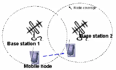
There are currently two categories of mobile wireless networks according the network structure. The first is known as the infra-structure based network. As shown in Fig. 1-1, this kind of network needs some basic fixed constructions, which are known as base stations. A mobile node can connect with a base station, if the mobile node is within the base station communication range. When the mobile node travels out of range of one base station and into the range of another, the mobile node can access the new base station instead of the old one seamlessly. This process also is called “hand-off”. The 2G or 3G cellular system is typically one of the networks.
On the other hand, the second type of mobile wireless network is the ad hoc
network [1]. Ad hoc network has no fixed routers; all mobile nodes are capable of movement and can be connected dynamically in an arbitrary manner. All mobile nodes of the network can function as routers, discover and maintain routes to other mobile nodes in ad hoc networks.
A Mobile Ad-hoc NETwork (MANET, Fig. 1-2) is a wireless network consisting of mobile nodes, which can communicate with each other without any infra-structure support, such as base stations. In these networks, mobile nodes typically act as routers and cooperate with each other, by forwarding packets for other mobile nodes which are not in the communication range of the source node.
Since MANET topologies change with time, unstable radio links due to the nature of time-varying network topologies and shadowing effect [2] of neighboring obstacles (moving vehicles) decrease the stability of the multi-hop
variation of radio channels and network topologies.
Figure 1-1. Infra-structure network scenario
Figure 1-2. Mobile ad hoc network scenario
The rest of this paper is organized as follows. Review of related works is given in chapter 2. In chapter 3, the proposed routing protocol for mobile ad hoc networks is proposed. Then, the simulation results and analyses of the proposed routing protocol are expounded in chapter 4. Finally, the conclusion of this paper is shown in chapter 5.
Chapter 2:Review of Related Works
Routing in mobile ad hoc networks (MANETs) has been widely studied by means of simulations, often using the 802.11b technology for the physical and MAC layers. MANETs are characterized by dynamic and unpredictable topology. An ad-hoc routing protocol is used to find out a feasible route that may pass through multiple radio links, i.e., multi-hop route for a specified source and destination pair (SD pair) in a time-varying network topology. Several researches on developing ad hoc routing protocols for MANETs have been proposed [3-8]. These routing protocols can be classified as table-driven
A. Table-Driven Routing Protocols
Table-driven routing protocols attempt to maintain consistent, up-to-date routing information from each mobile node to every other mobile node in the network. These protocols require each mobile node to maintain the routing-table which stores routing information. The routing-tables respond the changes in the network topology by periodically propagating the updates throughout the network. Then, each mobile node in the network can maintain a consistent network view. The process of maintaining the routing-tables cost lots of radio resources, even there isn’t any data transmission actually. Each mobile node also needs many memory units to store the routing-table, especially when the network scale is large. One of the main advantages of table-driven routing protocols is that a mobile node can find a route to the destination node quickly before transmission by looking up its routing-table.
Destination-Sequenced Distance-Vector Routing (DSDV) and Wireless Routing Protocol (WRP) are two of the table-driven routing protocols which are
often studied. The DSDV routing protocol is a table driven algorithm that modifies the Bellman-Ford routing algorithm to include timestamps that prevent loop-formation. The Wireless Routing Protocol is a distance vector routing protocol which belongs to the class of path-finding algorithms that exchange second-to-last hop to the destinations.
B. Demand-Driven Routing Protocols
A different approach from table-driven routing is source-initiated on-demand routing. This type of routing creates routes only when desired by the source node. Demand-driven routing protocols were designed on the purpose of reducing control overhead, thus increasing radio bandwidth and conserving power at the mobile nodes. These protocols limit the amount of radio bandwidth consumed by maintaining routes to only those destinations for which a source has data traffic. Therefore, the routing is source-initiated as opposed to table-driven routing protocols that are destination initiated. In another word, when a mobile node requires a route to a destination, it initiates the route
discovery process within the network. This process is completed when a route is
found or all possible route permutations have been examined. Once a route has been established, it is maintained by a route maintenance procedure until either the destination node becomes inaccessible along every path from the source node or until the route is no longer desired.
For the reasons of reducing control overhead, radio bandwidth and power consumption, many demand-driven routing protocol studies have been published. Before describing the proposed routing protocol, we highlight some key components. First, we describe the Ad hoc On-demand Distance Vector (AODV) routing protocol, which is one of the most been intensively studied demand-driven routing protocols, and its basic operation. Next, the related work including Signal Stability-based Adaptive routing (SSA) [9] and Associativity
Based Routing (ABR) [10] protocols are described. Finally, the pending problem and motivation of this research are also proposed.
2.1 Related Work
Several researchers have proposed adaptive ad hoc routing protocols, such as Signal Stability-based Adaptive routing (SSA) [9] and Associativity Based
Routing (ABR) [10], to improve the performance of discovered routes in MANETs. However, ABR and SSA still have some pending problems. ABR protocol would erroneously judge node stability from time-varying topology due to the radio propagation effects (see 2.2). And SSA protocol does not practically estimate the signal strength of the radio channel when the transmitting power and modulation mechanism are adaptable during data traffic transmitting process.
In this research, we modify the AODV routing protocol into a radio-link-adaptive routing protocol named as Ad-hoc On-demand Distance
Vector with forgetting factor (AODV-FF). A novel link stability estimating
method is defined based on exponentially weighted sums of practically obtained
signal strength at the receiving mobile nodes. Based on the proposed method for
link stability estimation, the proposed routing protocol explores and maintains the most stable routes, which provide high data throughputs and sufficient span of route lifetimes for all S-D pairs in MANETs.
2.1.1 AODV Routing Protocol
The Ad hoc On-demand Distance Vector (AODV) routing protocol is a demand-driven routing protocol. Therefore, the transmission routes are determined only when needed.
Step 1: Route Discovery - Generating Routing Requests
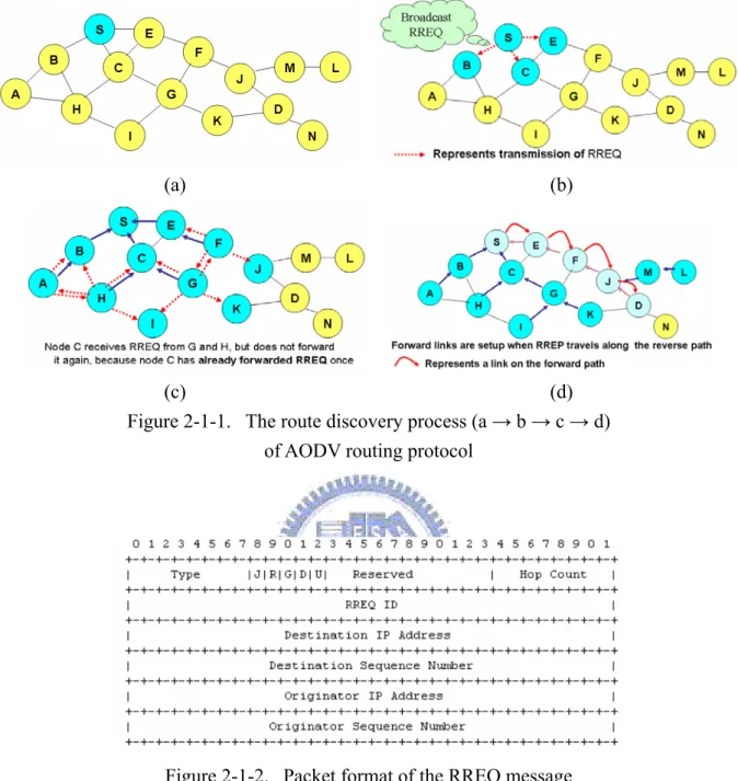
As shown in Fig. 2-1-1(a) (b), a mobile node disseminates a Route Request (RREQ / Fig.2-1-2) message when it determines that it needs a route to a destination and does not have one available. This process can happen if the destination node is previously unknown to the source node, or if a previously valid route to the destination node expires or is marked as invalid. The
Destination Sequence Number field in the RREQ message is the last known
destination sequence number for this destination node and is copied from the Destination Sequence Number field in the routing table. If no sequence number is known, the unknown sequence number flag (U) MUST be set. The Originator
Sequence Number in the RREQ message is the source node's own sequence
number, which is incremented prior to insertion in a RREQ message. The RREQ ID field is incremented by one from the last RREQ ID used by the current node. Each node maintains only one RREQ ID.
Step 2: Route Discovery - Processing and Forwarding Route Requests
If the receiving mobile node (which receives the RREQ message) has not received this RREQ before, is not the destination and does not have a valid route to the destination, it rebroadcasts the RREQ message. On the contrary, if such a RREQ message has been received, the node silently discards the newly received
RREQ message.
Step 3: Generating Route Replies
If the receiving mobile node is the destination or has a valid route to the destination node, it unicasts a Route Reply (RREP / Fig.2-1-3) message back to the source node. As the RREP message propagates, each intermediate mobile node generates a route to the destination node. When the source node receives the RREP message, it records the route to the destination node and can begin sending data. If multiple RREP messages are received by the source node, the route with the shortest hop count is chosen.
Step 4: Route Maintence
As data flows from the source node to the destination node, each mobile node along the transmission route updates the timers and sequence numbers associated with the route to the source node and destination node, maintaining the route in the routing table. If a route is not used for some period of time, a mobile node cannot be sure whether the route is still valid; consequently, the mobile node removes the route from its routing table.
Step 5: Route Error (RERR) Messages, Route Expiry and RouteDeletion
If data is flowing and then a link breakage is detected, a Route Error (RERR) message is sent to the source node from the mobile node that detects the link breakage occurrence. As the RERR message propagates towards the source node, each intermediate node invalidates routes to all unreachable destinations. When the source node of the data receives the RERR message, it invalidates the route and reinitiates route discovery process if necessary.
A mobile node initiates processing for a RERR message in three situations: (i) if it detects a link breakage for the next hop of an active route in its routing
table while transmitting data (and route repair was unsuccessful).
(ii) if it gets a data packet destined to a node for which it does not have an active route and is not repairing (if using local repair).
(iii) if it receives a RERR from a neighbor for one or more active routes.
Besides, the AODV routing protocol also uses the Hello message to detect and monitor links to all neighbors. If Hello messages are used, each active mobile node periodically broadcasts a Hello message to its neighbors. Because all mobile nodes periodically send Hello messages, if a node fails to receive several successive Hello messages from a certain neighbor node, a link breakage is detected.
(a) (b)
(c) (d) Figure 2-1-1. The route discovery process (a → b → c → d)
of AODV routing protocol
Figure 2-1-2. Packet format of the RREQ message
2.1.2 SSA Routing Protocol
The SSA routing protocol performs on-demand route discovery by selecting longer-lived routes based on signal strength and location stability. The signal strength criterion allows the protocol to differentiate between strong and weak channels. Each channel is characterized as strong or weak by the average signal strength at which packets are exchanged between the hosts at either end of the channel. The location stability criterion biases the protocol toward choosing a channel which has existed for a longer period of time.
The mobile node measures signal strength from other mobile nodes, and this information is used to estimate the link stability between them. According to the receiving signal strength, the link between self and a certain neighbor node can be classified two categories: 1. strong channel (the receiving signal strength ≧ a
certain threshold); 2. weak channel (the receiving signal strength < a certain threshold).
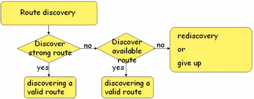
If a mobile node receives strong signal from a certain neighbor node, then these two nodes are closely located and the link between them can be considered as stable. In SSA routing protocol, each mobile node measures signal strength from its neighbor nodes. As shown in Fig. 2-1-4, in the first, SSA tries to find a route on these strong links with minimum hop counts. A route that is found through these strong links is known as a more stable route than an ordinary route. If it fails finding a route in first trial, or some strong link within the current-been-used route, it searches a route on all available links with minimum hop counts (Fig. 2-1-5).
Figure 2-1-4. SSA route discovery procedure
Figure 2-1-5. An example network
2.1.3 ABR Routing Protocol
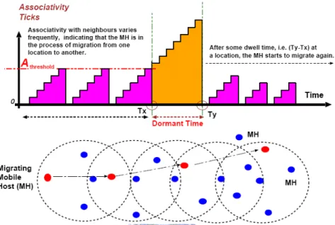
ABR uses pilot signal to determine link stability. As shown in Fig. 2-1-6, every mobile node sends pilot signals periodically. When a certain mobile node receives pilot signals from its neighbor nodes, it records pilot signals received (Fig. 2-1-7). In another word, every node in the ad hoc network learns its ‘Associativity’ with its neighbor nodes to determine the best route. Stability is determined using ‘associativity ticks’. If the mobile node receives these pilot
signals from a certain neighbor successively and the number of continuous pilot signals beyond certain threshes hold, it considers the link between them as stable link. Route search in ABR is different from SSA. In ABR, it searches all possible routes to find a route that contains more strong links. The route discovery procedure is shown in Fig. 2-1-8.
Figure 2-1-6. Time and spatial representation of associativity of
a mobile node with its neighbor nodes
Figure2-1-8. ABR route discovery procedure
SSA and ABR show an importance of link stability and their effects to a route in ad hoc wireless networks. However they focus on overall performance of networks. In this research, we analyze previous algorithms and compare them with AODV and our proposed routing protocol, AODV-FF.
2.2 Problems and Motivations
Several ad hoc routing protocols for MANETs have been proposed in recent years. Most of these routing protocols, such as Destination Sequenced Distance Vector (DSDV), Optimized Link State Routing Protocol (OLSR), Ad hoc On-demand Distance Vector Routing (AODV), and Dynamic Source Routing (DSR), are belong to min-hop routing protocols. These routing protocols discover the multi-hop routes for a given S-D pair based on the shortest path routing algorithm, which generally selects the route with minimum hop count. However, to our knowledge of characteristics of MANETs [11], the explored min-hop routes may be not so robust especially for time-varying radio channels and topologies. This phenomenon results in high packet loss rate and the decrement of data throughputs. The main factors to limit the performance of min-hop routing protocols can be categorized as following effects:
A. Radio Propagation Effect of Radio Links
Due to the radio propagation effects (Fig.2-2-1) including large-scale path loss and small-scale fading, radio links in MANETs would be strongly affected by physical environments, which cannot be solved by min-hop routing protocols.
Large-scale path loss includes the mean path loss and shadow fading, which represents the signal power attenuation due to radio propagation over large areas. The mean path loss is related to the environment parameters of propagation distance, the radio frequency, the height of the transmitter/receiver antenna and the radio propagation conditions. Besides, the mean path loss effect often
becomes significant as the propagation distance or the radio frequency increases. Small-scale fading refers to the dramatic changes in signal amplitude and phase that can be regarded as a result of small changes (as small as a half-wavelength) in the spatial separation between a transmitter and a receiver. Small-scale fading manifests itself in two mechanisms, namely, time-spreading of the signal (or signal dispersion) and time-variant behavior of the channel. For mobile radio applications, the channel is time-variant because motion between the transmitter and receiver results in propagation path changes. The change rate of these propagation conditions accounts for the fading rapidity. This effect decreases the stability of radio channels even when the average receiving power seems to be sufficient for the specified vehicle-to-vehicle communications.
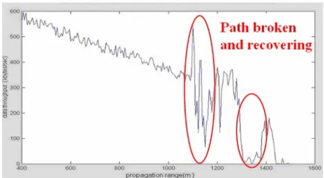
As a result, not only the network topology but also the quality of each radio channel in the network influences the performance of MANETs. As shown in Fig. 2-2-2, it shows the experimentation result of data transmission using AODV routing protocol on the road. The transmission path broken and recovering happened due to the radio propagation effects.
B. Edge Effect
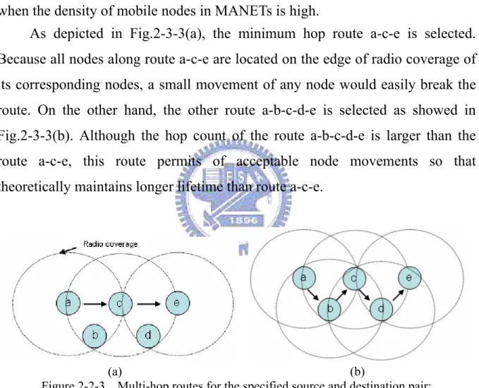
As we mentioned, shortest routes are unstable, which is due to the edge effect. Shortest routes may be composed of links that connect farthest neighbors. On these routes, nodes are located on the edge of other nodes’s radio propagation range. In this case, a small movement of any nodes can easily break the route. We name it as the edge effect. This phenomenon reveals obviously when the density of mobile nodes in MANETs is high.
As depicted in Fig.2-3-3(a), the minimum hop route a-c-e is selected. Because all nodes along route a-c-e are located on the edge of radio coverage of its corresponding nodes, a small movement of any node would easily break the route. On the other hand, the other route a-b-c-d-e is selected as showed in Fig.2-3-3(b). Although the hop count of the route a-b-c-d-e is larger than the route a-c-e, this route permits of acceptable node movements so that theoretically maintains longer lifetime than route a-c-e.
(a) (b)
Figure 2-2-3. Multi-hop routes for the specified source and destination pair: (a) the min-hop route; (b) a probable stable route.
Chapter 3:The Proposed Routing Protocol for Mobile Ad
Hoc Networks
The proposed AODV-FF routing protocol is modified from the existing AODV routing protocol, develops new link stability estimation, route maintenance and route discovery methods, which can enhance data throughput and route lifetime. As shown in Fig.3-1, the flow chart of the AODV-FF routing protocol is depicted. The proposed protocol is composed of three major processes, Link Stability Estimation, Route Discovery, and Route Maintenance. The followings are given to describe the details of these processes.
Figure 3-1. Flow chart of operating procedure of the proposed AODV-FF, three major processes are designed to evaluate, discover and maintain stable routes.
3.1 Link Stability Estimation Method
The estimation of link stability for a specified radio link is one of the critical issues in the proposed routing protocol. In this research, we declare that the radio links with high signal strength and long linking lifetime are regarded as stable links with high link stabilities. In contrast with purely referring to only one obtained receiving power at a given time, the proposed link stability estimation method monitors the received signal strength constantly and estimates the link stability with numerous recorded signal strength collected in the past. The proposed estimation method observes the temporal variation of the signal strength, so the link stability estimation method not only considers the present status of radio channels but also predicts the radio signal trend of radio channels between mobile nodes.
The link stability of ith radio link at time t is basically based on the following formulation:
∑
= − Δ − = m k i k i t S t t k L 1 )) 1 ( ( ) ( λ (1), where )) 1 ( (t−Δt k−Si denotes the link state, which is defined by:
∑
= Δ − = n j i i n j t p s n p S 1 )) ( ( 1 ) ( , (2),where n denotes the number of instantaneously sampled signal strength
within one unit time. ( ( ))
n j t p
si −Δ is the normalized signal strength value.
t
Δ unit time.
m number of unit times to show the effective length of memory.
λ an adjustable weighting parameter named as forgetting factor (FF)
A. an example of the link stability estimation method
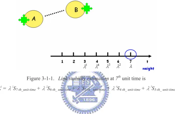
The forgetting factor controls the effective memory of the iterative processing of sequential information [13], which is adopted to predict the variation trend of radio link performance. Fig.3-3-1 shows the link stability estimation on 7th unit time.
Figure 3-1-1. Link stability estimation at 7th unit time is
i
L =λ1
S7-th_unit-time +λ2S6-th_ unit-time +λ3S5-th_ unit-time +λ4S4-th_ unit-time +λ5S3-th_ unit-time
B. an example of using the link stability estimation method in static network
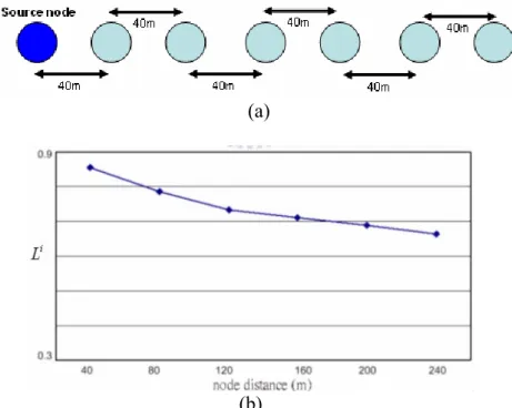
This experiment verifies the correctness and effectiveness of the proposed estimation method in static network. In this experiment, the link stabilities are obtained with the increasing of distance between two fixed nodes. As depicted in Fig.3-1-2, with the gradually increasing 40m of distance between the specified transmitter and receiver, the estimated link stabilities decrease gradually. In other words, the calculated link stability correctly represents the relative distance as well as large-scale fading effects for a given radio link.
(a)
(b)
Figure 3-1-2. Experimental scenarios for verifying the proposed link stability estimation method: (a) network topology (b) link stability vs. node distance
C. an example of using the link stability estimation method in dynamic network
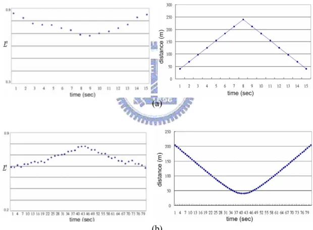
To validate effectiveness of the proposed estimation method, several experiments are made to obtain the relation of the estimated link stabilities and the states of radio links. Fig. 3-1-3 presents the experiments carried out by a fixed source (transmitting) node and a mobile destination (receiving) node with two given moving paths. In Fig. 3-1-3(a), the destination node moves far away from the source node and then backs. In Fig. 3-1-3(b), the destination node moves from position P to position Q. The moving speed of mobile node is 5m/s. Fig. 3-1-4 depicts the estimated link stability versus distance between the source and destination node, which shows that the estimated link stability decreases with the increasing of distance and the proposed method could properly reflects the moving trend of the mobile node.
(a)
(b)
Figure 3-1-3. Experimental scenarios for verifying the proposed link stability estimation method:
(a) destination node moves away from source node and backs; (b) destination moves orthogonally to source node
(a)
(b)
Figure 3-1-4. The estimated link stability variation with time-varying radio links between mobile nodes
3.2 Route Discovery Method
Step 1: Source node starts to find out the stable route by broadcasting the RREQ message.
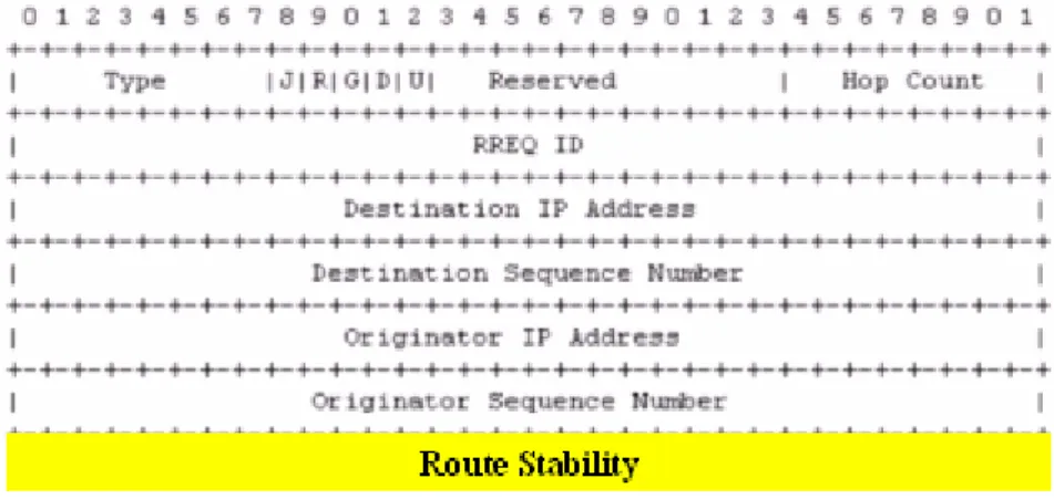
To fulfill dynamically occurred route request for a specified source and destination pair, the source node initiates a route discovery process by generating a Route Request (RREQ) message and broadcasting it to all its neighboring nodes. As shown in Fig.3-2-1, the format of proposed RREQ here is similar to the RREQ in AODV routing protocol but including a newly field named Route Stability (which initially set to 1 at source node).
Figure 3-2-1. Packet format of AODV-FF’s RREQ message
Step 2: Intermediate nodes restrict the flooding of RREQ message to reduce control overhead.
An intermediate mobile node might receive multiple RREQs and rebroadcast these messages during the route discovery process. To decrease the control overhead caused by flooding RREQ messages in MANETs, the intermediate mobile nodes rebroadcast the RREQ only with the maximum value in Route Stability field among the received RREQ messages.
Step 3: Nodes calculate route stability of eligible routes from the source to the intermediate node.
Before the intermediate node rebroadcasts the selected RREQ message, the mobile node needs to recalculate the Route Stability. The newly added Route Stability is equal the product of the original value in route stability field and the link stability of radio link between the receiving node and the broadcasting node that sent the RREQ message.
The format of the RREQ message in the AODV-FF is modified from the AODV routing protocol. A new field, named as Accumulated Link Stability (ALS) field is added. Partially determined ALS is recorded with the broadcasting RREQ messages. When the RREQ messages reach the destination node, it would record the ALS of the discovered routes, which are calculated from the collected link stabilities along the routes. The ALS of a certain route r is defined as:
∏
∈ ∀ = r P i i r L t ALS ( ) (3),where i denotes the link within the route r and Pr represents the link set
containing all links of the route r. In AODV-FF, the link stabilities of radio links connecting to all neighbor nodes are calculated and stored periodically in the
Node Link Stability Table (NLST). The link stabilities along each eligible route
are collected and accumulatively multiplied with the ALS value of the received RREQ messages.
Step 4: Destination node select the route with the maximum Route Stability.
As multiple RREQs continually arrive at the destination node, the destination node only receives the RREQs within a predefined time window, which starts at receiving the first arrival RREQ. After the destination node
determines the one with the maximum route stability, it creates a Route Reply
(RREP) message formatted similarly to AODV protocol for responding to its
precursor (the mobile node who sends the RREQ message adopted by the destination node).
Step 5: Intermediate nodes react RREP by building up the forwarding entries in the route tables.
When an intermediate node receives the RREP message, it sets up the forward entry to the destination node in its route table. After processing the RREP message, the intermediate node forwards the RREP message toward the source node along the reverse route through which the selected RREQ message passed.
Step 6: Source node discovers the selected route and start to transmit data.
When the source node receives the RREP message, the source node updates its route table to the destination node. For the time being, the stable route with maximum route stability is discovered. Then the handpicked stable route is available and prepared for data transmission.
Fig.3-2-2 shows an example that a source node S broadcasts the RREQ messages to find a proper route to the destination node D. Within a certain time interval T, the destination node D has collected two RREQ messages: the route (i) S→F→J→D and the route (ii) S→C→G→K→D with the route stability (accumulated link stability) being 0.07 and 0.1262 respectively. In this case, the destination node D will select the route with largest ALS value ( route (ii) ) depicted in Fig.3-2-2.
(a) (b) (c) (d) (e) (f) (g)
3.3 Route Maintenance Method
Due to the time-varying topologies of MANETs, the stability of the connecting routes would change with time. In order to react the change of route stability and ceaselessly maintain a stable route, a Route Maintenance process is proposed. In this process, stabilities of the connecting routes are continuously evaluated. If the stability of any route goes poor, the source node will try to discover another stable route to replace the original one. The detail of the process is presented as following steps:
Step 1: Source node periodically probes the stability of the connecting route.
The source node periodically invokes Route Stability Probe (RSPB) messages and sends them to the destination node in every predefined time interval Tp. The RSPB is operated similar to the RREQ described in the route
discovery process, but it is only forwarded along the connecting route to be estimated.
Step 2: Intermediate nodes recalculate the stability of the connecting route.
When an intermediate node along the connecting route receives a RSPB packet, the Route Stability field in the RSPB is recalculated based on the present link stability information stored in the NLST. Then the updated RSPB would be forwarded to the next hop node of the connecting route.
Step 3: Destination node determines whether the connecting route is still stable or not.
In the destination node, the most up-to-date stability of the connecting route is obtained by the RSPB. If the route stability is less than a predefined threshold κ, the destination node replies a Rerouting Request (REREQ) back to the
source node. Otherwise, it sends a Probe Acknowledgement (PACK) to return the obtained route stability and the process goes back to Step 1.
Step 4: Source node re-discovers another stable route if necessary.
Within a predefined time interval, if the source node did not receive the expected PACK (which indicates the connecting route is broken) or it receives a REREQ (which indicates the connecting route goes unstable), it performs the route discovery process to find another route to replace the connecting route.
Chapter 4:Simulation Results and Analyses
In order to evaluate the performance of proposed AODV-FF routing protocol, the NCTUns network simulator [14] is employed. In this paper, we comparing four routing protocols, AODV, AODV-FF, SSA and ABR. Among them, SSA and ABR are two well-known routing protocols which are studied and proposed to improvement the route stability of MANETs. Besides, the UDP transport layer protocol is used to obtain the data throughput between a specified S-D pair. As to the physical layer and MAC layer protocols, the IEEE 802.11b is selected. To include the practical characteristics of radio propagation channels, a large-scale median path-loss model and a small-scale fading model are also chosen in NCTUns. The random waypoint mobility model is chosen to emulate the moving pattern of each node.
The AODV-FF, SSA, ABR and AODV routing protocols are evaluated in free-space propagation environment. In this paper, three types of scenarios are considered. The simulation scenarios and result analyses are discussed in following subsections.
4.1 Performance Metrics
Several metrics could be defined to evaluate the performance of the MANET. Here we consider two of significant metrics in order to determine the performance of the MANET routing protocols in our simulations.
z Data Throughput.
Data throughput T is defined as the average size of a given packet, divided by the corresponding average transmission time between a specified SD pair. In our simulations, each SD pair intends to maximize the number of transmitted packets while minimizing the average transmission time.
And the data throughput improvement ratio Tr is defined as:
% 100 × − = ref ref cmp r T T T T (4) where cmp
T is the average data throughput of the selected routing protocol.
ref
T is the average data throughput of the referenced routing protocol.
z Average Route Lifetime.
Average route lifetime τ is defined as:
m ttransmission = τ (sec) (5) where on transmissi
t is the accumulated connecting time interval during the data
transmission process between a certain SD pair.
And the route lifetime improvement ratio
τ
r is defined as: % 100 × − = ref ref cmp r τ τ τ τ (6) where cmpτ is the average route lifetime of the selected routing protocol.
ref
τ is the average route lifetime of the referenced routing protocol.
In each scenario, the higher the average route lifetime is, the more stable the connecting route is. This index shows the stabilities of the connecting routes explored by the MANET routing protocols.
4.2 Performance of AODV-FF among different FF values
First of all, the correlation between the MANET performance and the quantity of FF is discussed. The data throughputs of a given MANET scenario with various FF settings are obtained in this test. The moving speed of all mobile nodes is 10 m/s. As shown in Fig.4-2-1, the average data throughputs change with the different FF values. The best average data throughput is obtained while the FF value is set to 0.55. This phenomenon implies that a better MANET transmission performance might be achieved with a correctly selected FF value. It also means that the proposed protocol has the ability to adapt itself to different environments by adaptively adjusting the FF.
Table 1. Parameters set up for section 4.2
Parameters Assigned values
Area of operation (m2) 700 × 700
Number of nodes 25
Value of forgetting factor λ 0.55 Initial topology 5 × 5 grid Moving speed of nodes (m/s) 10 Variance of small-scale fading effect (db) 20 Transmission range of single radio link (m) 200 Received power sensitivity and threshold γ (db) -74
Simulation time (sec) 300
Figure 4-2-1. Average throughput vs. forgetting factor by using AODV-FF routing protocol
4.3 Moving-Speed Effect
In this test, the average data throughput and average route lifetime under various moving-speeds of mobile nodes are considered, which determine the temporal variation of topology. Fig.4-3-1 and Fig.4-3-2 illustrate the average data throughput and its improvement ratio, versus moving speed respectively, using AODV, SSA, ABR and AODV-FF routing protocols. By examining the results, the proposed AODV-FF routing protocol performs better than all the other routing protocols in all test cases. As shown in Fig. 4-3-1, this result validates the effectiveness of our proposed route maintenance process, which
can decrease the route breakage probability. Because the min-hop routing protocols do not take time-varying stabilities of radio links into account, the data throughputs and route lifetimes using AODV may have large variation, which yields an unstable performance. On the other hand, the proposed AODV-FF protocol can maintain a stable and good performance. This results a large variation of data throughput difference between AODV and AODV-FF. This phenomenon is observed in Fig. 4-3-1.
At the node moving speed equals 12 m/s, the average data throughput improvement ratios of AODV-FF are up to 78%, 19%, and 67% comparing to AODV, SSA and ABR respectively. Due to route maintenance process, which can effectively extend route lifetime by periodically discovering stable routes for all connecting routes, the improvement ratio obtained by AODV-FF is much higher than that by SSA and ABR. There is a trend shown in Fig. 4-3-2 that the improvement ratio of AODV-FF increases with moving speed and this phenomenon is obvious when the moving speeds are in the range from 9 m/sec to 18 m/sec. This improvement is not so obvious when the moving speed of nodes is high as 21 m/sec. It is because that ARLs are small for fast time-varying topologies and in nature are not easy to be improved. In addition, the average throughput of AODV-FF is better than other routing protocols at various moving speeds.
Fig.4-3-3 and Fig.4-3-4 depict that the average route lifetime of AODV-FF is much longer than the lifetime of the other routing protocols. The relative ratios of the average route lifetime are presented in Fig.4-3-4, which shows that the proposed AODV-FF routing protocol significantly increases the average route lifetime. In the moving speed such as 6m/s, AODV-FF raises more than 102% of average route life time comparing to AODV. This phenomenon shows that the route discovered by AODV-FF protocol is much more reliable for failure-sensitive communication services such as video and audio streaming.
Table 2. Parameters set up for section 4.3
Parameters Assigned values
Area of operation (m2) 1500 × 1500
Number of nodes 25
Value of forgetting factor λ 0.55 Initial topology 5 × 5 grid Moving speed of nodes (m/s) 3 ~ 21 Variance of small-scale fading effect (db) 20 Transmission range of single radio link (m) 200 Received power sensitivity and threshold γ (db) -74
Simulation time (sec) 400
Figure 4-3-1. Average data throughput vs. moving speed by using AODV, ABR, SSA and AODV-FF routing protocols
Figure 4-3-2. Data throughput improvement ratio of the chosen routing protocols compared with AODV
Figure 4-3-3. Average route life time vs. moving speed by using AODV, ABR, SSA and AODV-FF routing protocols
Figure 4-3-4. Route life time improvement ratio of the chosen routing protocols compared with AODV
4.4 Topology-Size Effect (Constant Node Density)
In this simulation scenario, the data throughput and average route lifetime among different topology-size are investigated. For each topology-size, all mobile nodes move according to the Random Waypoint model. Then different routing protocols are employed to obtain their performance. The simulation parameters are given in Table 3.The initial network topologies are squared grids, which are of sizes: 2x2, 3x3, 4x4, and 5x5 grids.A constant node density is kept and it is equal to
22500
1 (nodes/m2). The moving area is confined to keep a
constant node density in each topology-size.
Table 3. Parameters set up for section 4.4
Parameters Assigned values
Area of operation (m2) 3002 、4502 、6002 、7502
Number of nodes 4、9、16、25
Value of forgetting factor λ 0.55 Initial topology squared grids Moving speed of nodes (m/s) 10 Variance of small-scale fading effect (db) 20 Transmission range of single radio link (m) 200 Received power sensitivity and threshold γ (db) -74
Simulation time (sec) 400
Fig.4-4-1 and Fig.4-4-2 depict data throughputs and its improvement ratios, respectively, versus node number. Cases using AODV, ABR, SSA and AODV-FF are all considered. The data throughput decreases as topology-scale increases, which is shown in Fig. 4-4-1. This phenomenon is due to the number of a route hop count increases.
From Fig.4-4-2, it is found that not like other routing protocols, the average data improvement ratio of the proposed AODV-FF is increased as the size of network topology size increases. It is because that the probability of the shortest-path route being the optimum route decreases due to the increasing of topology-size that yields large number of available routes.
Fig. 4-4-3 and Fig. 4-4-4 show the average route lifetime versus number of nodes and improvement ratios of average route lifetime versus number of nodes, respectively. Comparing to the AODV protocol, both the AODV-FF and SSA not only discover stable routes but also increase the average route lifetime significantly. Among all test cases, the proposed AODV-FF always can discover stable routes and provides the longest route lifetime for specified SD pairs. From Fig. 4-4-4, large improvement ratio of average route lifetime are obtained using AODV-FF, which is equal to 36.3%, 301%, and 376.7% with 9 nodes, 16 nodes, and 25 nodes, respectively. The improvement ratios obtained by AODV-FF is much higher than that by SSA and ABR. There is a trend that the improvement ratio of AODV-FF increases with topology-size when the number of nodes is in the range from 9 nodes to 25 nodes.
Figure 4-4-1. Average throughput vs. node numbers by using AODV, ABR, SSA and AODV-FF
Figure 4-4-2. Data throughput improvement ratio of the chosen routing protocols compared with AODV
Figure 4-4-3. Average route life time vs. node numbers by using AODV, ABR, SSA and AODV-FF
Figure 4-4-4. Route life time improvement ratio of the chosen routing protocols compared with AODV
4.5 Topology-Size Effect (Various Node Density)
In this simulation, the data throughput and its improvement ratio among different topology-sizes are investigated. The numbers of mobile nodes are 16 nodes, which are all moving in 600m×600m, 800m×800m, 1000m×1000m and 1200m×1200m free space respectively. Fig.4-5-1 shows that the data throughputs provided by AODV-FF are better than other three routing protocols in all topology-sizes. By examining Fig.4-5-2, the average data throughput improvement ratio of the proposed routing protocol is higher than all the other routing protocols in all test scenarios. The AODV-FF significantly improves data throughputs up to 37% comparing to AODV, up to 20% comparing to SSA and up to 22% comparing to ABR when 16 mobile nodes move in 800m×800m area.
Fig. 4-5-3 and Fig. 4-5-4 show the average route life time improvement ratio can even up to 4 times long comparing to AODV in 600m×600m area.
Table 4. Parameters set up for section 4.5
Parameters Assigned values
Area of operation (m2) 6002 、8002 、10002 、12002
Number of nodes 16
Value of forgetting factor λ 0.55 Initial topology squared grids Moving speed of nodes (m/s) 10 Variance of small-scale fading effect (db) 20 Transmission range of single radio link (m) 200 Received power sensitivity and threshold γ (db) -74
Simulation time (sec) 400
Figure 4-5-1. Average data throughput vs. area size by using AODV, ABR, SSA and AODV-FF routing protocols
Figure 4-5-2. Data throughput improvement ratio of the chosen routing protocols compared with AODV
Figure 4-5-3. Average route life time vs. area size by using AODV, ABR, SSA and AODV-FF routing protocols
Figure 4-5-4. Route life time improvement ratio of the chosen routing protocols compared with AODV
Chapter 5:Conclusion
In this paper, a radio-link-adaptive ad hoc routing protocol with a novel link stability estimation method for the MANET is proposed. In this protocol, new methods for link/route stability estimation are proposed based on a mobile-to-mobile radio propagation model, and a stability-based routing algorithm is designed to find out the stable route for a specified SD pair. The main contribution of the proposed AODV-FF routing protocol is the capability to improve the average data throughput, average route lifetime, and bandwidth utilization from the existing minimum hop ad hoc routing protocols like AODV. Simulation results indicate that the AODV-FF performs better than AODV, SSA and ABR by increasing the average data throughput and average route lifetime in various testing scenarios. In addition, the forgetting factor, which is regarded as an adjustable weighting parameter for link stability estimation, provides the flexibility to adapt to heterogeneous scenarios.
Our future works will focus on intelligent mobile ad hoc routing protocols and required adaptive mechanisms for the MANET. First of all, an intelligent link stability estimation method for proposed AODV-FF by dynamically adjusting the forgetting factors would be investigated. Advanced cross-layer design or self-learning mechanism for route discovering and maintaining processes are also considered.
Reference
[1] C.E. Perkins, Ad hoc networking, Addison-Wesley, 2001.
[2] B. Sklar, “Rayleigh fading channels in mobile digital communication systems part I: characterization,” IEEE Communications Magazine, July 1997.
[3] E. Royer and C.K. Toh, “A Review of Current Routing Protocols for Ad Hoc Mobile Wireless Networks,” IEEE Personal Communications, April 1999, vol. 6, no. 2, pp. 46. [4] C. Perkins and P. Bhagwat, “Highly Dynamic Destination-Sequenced Distance-Vector
Routing (DSDV) for Mobile Computers,” In Proceedings of the ACM SIGCOMM, pp. 234-244, 1994.
[5] P. Jacquet, P. Muhlethaler, T. Clausen, A. Laouiti, A. Qayyum, and L. Viennot, “Optimized Link State Routing Protocol for Ad Hoc Networks,” In Proceedings of the
IEEE International Multi Topic Conference, pp. 62-68, 2001.
[6] C. Perkins and E. Royer, Ad hoc On-Demand Distance Vector Routing, In Proceedings
of the 2nd IEEE Workshop on Mobile Computing Systems and Applications, pp. 90-100,
1999.
[7] D. B. Johnson, D. A. Maltz, and J. Broch, DSR: The Dynamic Source Routing Protocol
for Multi-Hop Wireless Ad Hoc Networks, In C. E. Perkins, editor, Ad Hoc Netowrking.
Addison-Wesley, 2001.
[8] Z.J. Haas, M.R. Pearlman, and P. Samar, “The Zone Routing Protocol (ZRP) for Ad Hoc Networks,” Internet draft, Aug. 2002.
[9] R. Dube, C.D. Rais, K.Y. Wang, and S.K. Tripathi, “Signal stability based adaptive routing (SSA) for ad hoc mobile networks,” IEEE Personal Communications, vol. 4, no. 1, pp. 36-45, 1997.
[10] C.K. Toh, Associativity-based routing for ad hoc mobile networks Wireless Personal Communications, vol. 4 no. 2, pp. 103-139, 1997.
investigation of mobile ad-hoc networks in vehicular environments,” in Proceedings,
IEEE Intelligent Vehicles Symposium, June 2005.
[12] G. Lim, K. Shin, S. Lee, and H. Yoon, ”Link stability and route lifetime in ad-hoc wireless networks,” in Proceedings, IEEE ICPPW, 2002.
[13] S. Haykin, Adaptive filter theory 4ed, Prentice Hall, 2002.
[14] S.Y. Wang, C.L. Chou, C.H. Huang, C.C. Hwang, Z.M. Yang, C.C. Chiou and C.C. Lin, “The design and implementation of the NCTUns 1.0 network simulator,” Computer
Networks, vol. 42 no.2, pp. 175-197, 2003.
[15] M. Gerharz, C. Waal, M. Frank, P. Martini, “Link stability in mobile wireless ad hoc networks,” IEEE LCN’02.
[16] C.F. Chiasserini, M. Meo, “An innovative routing scheme for 802.11-based multi-hop networks” IEEE 2004.
[17] E. Weiss, K. Kurowski, S. Hischke, B. Xu, “Avoiding route breakage in ad hoc networks using link prediction,” IEEE ISCC’03.
[18] P. Best, S. Gundeti, R. Pendse, “Self-learning ad-hoc routing protocol,” IEEE 2003. [19]W. Su, S. Lee, and M. Gerla. Mobility Prediction and Routing in Ad Hoc Wireless
Networks. International Journal of Network Management, Wiley & Sons, 11:3–30, 2001. [20] J.H. Song, W.S. Wong, C.M. Leung, “Efficient On-Demand Routing for Mobile Ad Hoc
Wireless Access Networks,” IEEE journal on selected areas in communications, vol. 22, No. 7, September 2004.