Syn th e sis of AGVS by coloure d-tim e d Pe tri n e ts
SUH UA H SIEH
Ab stract. Th e pape r presents a ne w AGVS m ode lling m e thod using a class of com m and-place colou re d-tim e d Pe tri n ets ( CP-CTPN) . Th e CP-CTPN is cap able of m ode llin g m an y distinctive AGVS fe atures, such as the functions of zon e con trol and ve hicle blockin g, that are not ge ne rally available in m ost ge n e ral-p urpose com m e rcial program m e s. In th e prop osed ne w m odelling m e th od, the CP-CTPN is gen erated syste m atically in four ste ps by sim ply givin g a floor-path layout an d a m an agem e nt policy. Th ese four m ode lling ste ps are ; ( 1) to con struct a PN-base d floor-path m ode l by asse m blin g modu lar PN sub-m ode ls, ( 2) to incorp orate coloured tokens an d tim ed transitions into a CTPN, ( 3) to gen erate veh icle move m ent se que nce s by in troducin g re lay functions and manage m e nt com m ands into CP-CTPN, an d ( 4) to com pute re achable m arkings evolve d from initial m arking by incorpor-ating th e prod uct of a coloured incide nt m atrix and a firing seque nce . Two floor-path e xam ple s, given by Hsieh and Sirinivasan, are pre se nted to show th e e ffective ne ss of the me thod. Sim ulation results using the pre se nt m ethod indicate that both the re quire d fractions of time that a ve hicle travels loaded and unloaded are som e what high er than those of Sirinivasan’ s. Th at is be cause the present m e th od allows m any functions to be m ode lle d in de tail th at are n ot available in othe r approache s.
1. In tro d u c tio n
Mate rial h andlin g is one of th e m ost im portant tasks in an autom ate d m an ufactu rin g system ( AMS) . Au to-m ate d guide d veh icle s ( AGV) , travellin g ato-m on g work-stations and autom ate d storage
/
re trie val system s ( AS/
RS) , are th e m ate rial han dlin g tools com m on ly used in an AMS. Sin ce th e flexibility of an AGV system is m uch con fin e d by its original design, it is often de sirable to de ve lop a com pute rize d m ode llin g m e th od th at can system atically gen e rate an AGVS of great fle xibility.Th e de sign of an AGVS can gen e rally be divide d into th re e levels, n am ely, th e le ve ls of de vice, floor an d m anage m e n t. In de vice de sign le ve l, the h ardware of ve hicles is care fully plan ne d, de signe d an d fabricate d. Th e se tasks are usually don e by m anufacture rs. A few te ch nical pape rs are available in th is area. In floor de sign level, a de tailed layout of floor-path is care fully
plan n e d an d im ple m e nte d. It is usually don e by th e floor m anage r. Since it is application depe nde n t, it can not be ge n erated inde pe n de ntly with out a priori system kn owle dge . Variou s floor-path layou ts we re prop ose d an d care fully studie d by re se arch e rs ( Gaskins an d Tan ch oco 1987 , Kasp i an d T an ch oco 1 990, Ve n kataram an an an d Wilson 1991) . The proble m of locating pick-up an d de live ry station s was studie d by Goe tz an d Egbe lu ( 1990) . A system atic floor-p ath Pe tri-n e t re pre se tri-n tatiotri-n m e th od was propose d by Hsie h atri-n d Shih ( 1992, 1994) . In m an age m e nt de sign le ve l, th e m an agem e nt policy is tran slated in to a se t of dispatch -in g an d rou te -in g ru le s. Th e de te rm -in ation of a m an age m e n t policy is also application d e pe n de n t. The problem s of de term inin g a re quire d num be r of veh icle s for a system we re studie d by Maxwe ll an d Mu ckstadt ( 1982) , Ne wton ( 1985) , Egbe lu ( 1984) , Tan ch oco et al. ( 1987) , and Lin ( 1990) . Th e problem s of ve hicle dispatch ing and routein g we re studie d by Egbe lu an d Tan choco ( 1984) , Hodgson et al. ( 1987) , Kim ( 1990) an d Yim et al. ( 1993) . A varie ty of m an agem e nt rule s h ave be en propose d in th e se studies. Sin c e th e re are too m an y ap p lic ation factors in volve d in an AGVS de sign proce ss, a sim ulation m odel is usually use d for study. Although the re are se ve ral gen e ral-purp ose com m e rcial sim ulation program m e s available on th e m arket, th e y are too ge ne ral to in clude spe cific AGVS fe ature s such as zon e con trol an d traffic blockin g in th e m ode l. Th e AGVS m odels gen e rated by gen e ral purpose com m e rcial package s are le ss accurate sin ce m an y fe ature s are ne gle cte d or ide ally approxi-m ated by oth e r approxi-m e ans in the ir prograapproxi-m approxi-m es. Gaskins an d Tan ch oco ( 1989) de ve lope d an AGVS de sign tool, AGVSim 2, for fre e -ranging veh icle m anage m e nt. AGV-Sim 2 focuse s on the m an age m e n t strategie s of an AGVS rathe r th an on the con struction of a sim ulation m ode l. Since th e con struction of a sim ulation m ode l is te dious an d tim e -con sum ing, it be com e s ve ry difficult to obtain an optim al solution in an AGVS de sign proce ss.
Th e obje ctive of th is pape r is to de ve lop a m e th od th at can system atically gen e rate sim ulation m odels for an AGVS base d on a propose d m ode lling strate gy. Sim ulation m ode ls are con structe d and solve d by a
0951-192X/98 $12.00Ó 1998 Taylor & Francis Ltd
Au thor: Suh u a Hsieh , De partm e n t of Me ch an ical Engine ering, National Taiwan
com p ac t com pu te r p rogram th at con ve rge s to a solution ve ry qu ickly. Th e m ode lling procedure is prese n te d be low.
2. PN re p re se n tation o f a give n flo o r-p ath layou t
Sin ce th e AGVS d e sig n p roce ss is app lication de pe nde n t, it is ge n e rally difficult to plan for a ne w AGV system sim ply by m odifying an e xistin g on e . Howe ve r, it is inde e d possible to con struct a ne w system by com binin g m odular fe ature s of th e system . Hsie h an d Lin ( 1991) pre se n ted four basic flow-path m odule s of un idire ction al AGVS in te rm s of Pe tri ne ts. Th e work was exte n de d to m ode l bi-direction al system s by Hsie h an d Shih ( 1992) . Zone con trol n e ts we re in troduce d to th e flow-path m odel in th eir m ode l. To assure the robustn ess of th e m ode l, se ve ral system propertie s we re care fully exam in e d. The se prope rtie s in clude , ( 1) collision -fre e traffic flow, ( 2) conse rvation of ve h icles and con trol signals, ( 3) floor-path re ach ability, an d ( 4) de adlock-fre e structure. By th e em ploym en t of in varian t proper-ties an d reach ability tre e of Pe tri n e ts, the prope rtie s of safene ss, boun de dne ss, strict con se rvation , re ach ability, an d live n ess of e ach sub-ne t we re carefully che cke d. By putting sub-ne t m odule s togeth e r, a com plete robust floor-path m ode l was con structe d system atically in te rm s of Pe tri n e ts. In ord e r to d e ve lop th e p rop ose d m ode llin g m e thod, som e fun dam e n tal buildin g block elem en ts are de fin e d an d prese nte d be low.
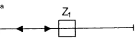
2.1. On e-dead-en d bi-directional lin e structu re
Th e bi-dire ction al lin e structure is com pose d of two un idire ction al line structure s with opposite travellin g dire ction s. Som e typical bi-dire ction al path se gm en ts ne e de d in an AGVS are th e path se gm en ts to h om e , to re st areas, an d to pickup
/
delive ry poin t of th e storage are a. A bi-direction al path se gm en t usually le ads to a de ad-en d and thus a one -de ad-e nd bi-dire ction al lin e ne t is usually use d. Figures 1( a) and 1( b) sh ow a typical on e -d e ad-e n d bi-d ire ction al lin e stru ctu re an d its associate d Pe tri-ne t sub-m ode l.2.2. Station-zone-macro stru ctu re
A station is usually locate d n e ar an AGV path zone . It con sists of one in put buffer, on e output buffe r an d on e m ach ine . Wh e n a ve h icle stops at a station, it pe rform s th e task of loading
/
unloading to/
from th e input/
output buffer. Se n sors are e quippe d in buffe rs to de te ct the e xiste n ce of parts. If the ve h icle is loaded an dth e buffe r is e m pty, th e con trolle r will issu e an un loadin g com m and to the ve hicle . If th e ve h icle is e m pty and th e buffe r is loade d, th e con trolle r will issue a loadin g com m an d to th e ve hicle . Th e m ach in e in th e station -zon e re ce ive s a part from the input buffe r, proce sse s it an d th e n m ove s it to the output buffers on ce it is don e . A typical station -zone m acro n e t is give n in figure 2. In this ne t, Zpis a zone -place ne are st to th e
station am on g all zon e s, wh e re th e subscript p is th e in de x of a zon e. MCn is a tim e d-place showin g th e
re quire d proce ssin g tim e of a m achine , wh e re th e subscript n is th e in dex of a m ach in e . IB is a place for in put buffe r. O B is a place for output buffe r. JS is a place th at issues `job is don e ’ sign al to th e con troller. RS is a place that receives `job reque st’ sign al from th e
a
Figure 1(a). The one-dead-end bi-directional line structure.
Figure 2. The station-zone macro net.
b
con trolle r. Sin ce th e ope ration s of loading and un load-ing usually take tim e s, the transitions of tp1, tp2, tn1an d
tn2are tim e d-transition s.
Th e station zon e m acro n et de scribe s activities th at are re late d to the station . Th e re ason to introdu ce a station-zon e m acro n e t he re is to e n able the m e asure of average waitin g tim e of a part in a station. Th e station -zone m acro n et is usually em be dde d in the associate d zone -place . In oth e r words, th e tim e spe n t to process a spe cific part can be m e asure d via th e refine m e n t of th e station-zon e place in th e m ode l. Wh e n e ve r a zon e -place in a floor-le ve l m od el is a station-zon e, the zon e -place sh ould be replaced by a station -zone m acro place .
2.3. Combin ation ru les
Modular basic flow-p ath ne ts can be com bin e d to gen e rate a com ple te ne t structure . Since two place s
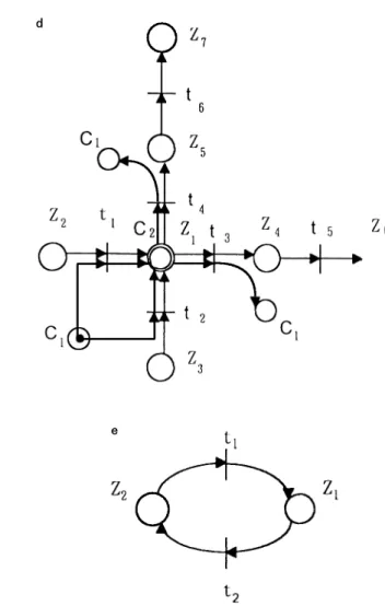
can not be conn e cte d dire ctly, transition s are use d to con n e ct the output place s of prece ding n e t an d th e in put place s of th e succe e ding n e t. A dash ed circle is use d to re pre sen t the conn ecte d place . Th e com bine d structure is calle d the m odular con n ectin g ne t. Figure s 3( a) ± 3( e) sh ow th e m odular con ne ctin g n e ts of the line structure , th e divide structure , th e m e rge structure , the in te rsec-tion structure, an d the on e -de ad-e n d bi-dire crsec-tional lin e structure. He re L stands for a lin e structure , D stands for a divide structure , M stands for a m e rge structure , I stands for an in terse ction structure , an d BL stands for a on e -de ad-e n d bi-dire ction al structure . Th e com bin ation rule s can be sum m arize d as follows.
1. A dash ed-lin e place in pre ceding ne t should be con ne cte d to a solid-lin e place in succe e ding ne t. 2. A dash edlin e ( solidlin e ) place cann ot be con -n ecte d to a solid-li-n e ( dash e d-li-ne ) place i-n th e same n et.
Figure 3. The modular connecting nets of (a) line structure, (b) divide structure, (c) merge structure, (d) intersection structure, and (e) BL structure. a b c d e
2.4. PN modellin g procedu re
Th is section is devote d to the PN m ode llin g of a give n floor-path layout. To sum m arize the m ode llin g proce ss, a procedure of six ste ps is prese nte d as follows. 1. Specify the basic flow-path types of a give n AGVS
floor-path layout.
2. Gen e rate basic m odular conn ectin g n ets for e ach flow-path type of lin e, divide , m e rge , in te rse ction , an d on e -de ad-e nd bi-dire ctional lin e .
3. Com bine m odular conn e ctin g ne ts to obtain a com ple te floor-p ath n e t usin g com bination rules. 4. Inspect wh e th er th e com plete floor-path n et is
close d? If not, go back to ste p 3.
5. Re place a zon e -place by a station -zon e m acro place if a station is pre sen t n e ar a zone .
6. Stop.
3. CTPN re p re se n tation o f co lo u re d to ke ns an d tim e d transitio n s
Th e floor-path PN m ode l con structe d above can be m ade m ore com pre h e nsive by in corp orating coloure d token s an d tim e d transition s
/
place s. Coloure d token s are in troduce d to re pre sen t the en titie s of ve h icle s an d statuse s of ve h icle s, m ach in e s an d buffe rs. Tim e d transitions are use d to m e asure th e pe rform an ce tim e of the veh icle s. Tim e d place s are use d to m easure th e proce ss tim e of th e m achin e . Afte r puttin g coloure d token s into places and addin g tim e in to som e transi-tions and place s of the PN m od el, the system can th e n be e xpre sse d in term s of a coloure d-tim ed Pe tri n e t ( CTPN) m odel.3.1. Colou red an d timed Petri n ets
In a place -transition n e t, it is often n ecessary to h ave se ve ral ide n tical ne ts since a folding in to a single sub-ne t will de stroy th e possibility to distin guish diffe re n t proce sse s. In th at respe ct, Ge nrich an d Laute n bach ( 1981) developed pre dicate-transition ne ts ( PrTNs) . In PrTNs, inform ation is attach ed to e ach token by a toke n -colour an d e ach transition can occur in several ways re pre sen te d by diffe re n t occurre nce colours. Wh e n a transition is fire d, the re lation be twe en occu rre n ce colours is de fin e d by the expre ssion s attach e d to th e arcs. Re striction s on the possible occurren ce colours can be im posed by a pred icate th at is attach e d to th e transition. In spire d by PrTNs, Jen sen ( 1981, 1983) h as propose d Coloure d Petri ne ts ( CPNs) . Th e re lation be twe e n an occurre n ce -colou r and a toke n colour
in volve d in the firin g of a transition is define d by th e fun ction s attache d to th e arcs. More ove r, CPNs e xplicitly attach a se t of possible toke n-colou rs to e ach place , an d a se t of possible occurre nce -colours to each transition. By so doin g, th e place -in variant can be in te rprete d an d th e e le m e nts of th e in cide n ce -m atrix be com e fun ction s in ste ad of in tegers.
Sin ce an e ve n t is com ple te d after a se quen ce of activities are pe rform e d by the system . In othe r words a ce rtain am oun t of transition tim e is e lapsed be twe e n two con se que n t e ve n ts. Th e tim e e p oc h can th u s be associate d with transition s. The ch oice of tim e associate d with transition s is one of th e popular topics in th e study of Tim e d Pe tri-n e ts TPNs ( Viswan adham and Narahari 1992) . It is n ote d that Pe tri n e ts with tim e d transition s are e quivalen t to Pe tri n e ts with tim e d place s. Se ve ral re se arche rs ( Ram ch an dni 1973, Sifakis 1977, Ram a-m oorth y an d Ho 1980) inve stigated th e type of tia-m e d Pe tri ne ts in wh ich place s or transitions we re associate d with de te rm inistic tim e duration . The an alysis of such tim e d Pe tri ne ts is, howe ve r, tractable on ly for som e spe cial classes such as m arke d graphs. The in troduction of associating ran dom tim e duration was first explore d in de pe nde n tly by Natkin ( 1980) an d Molloy ( 1982) . This study was th e starting point for th e e m erge n ce of Stoch astic Pe tri n ets ( SPNs) that was late r e xte nde d an d use d as a prin ciple pe rform an ce m odellin g tool for discre te e ve nt syste m s. O ur focus in th is pape r is on th e de te rm in istic TPNs and SPNs. We will con side r both transitions an d place s associate d with tim e .
3.2. Colou red vehicles
Ve hicle s are ide n tical in th e ir fun ction ality. It is th e status attribute s ( e .g., loade d, e m pty with assign m en t, e m pty without assignm en t, e tc.) , th e location s of th e veh icle , an d th e priority of tasks that m ake the m diffe re n t from e ach oth e r. For instance , if a part is waiting to be transfe rre d from one station to anoth e r, ve h icle A is fre e an d it is also in sh orte st distance to th e part am ong fre e veh icle s, ve hicle A is th e n give n th e high est priority for th e job. Th e re fore, it is ve ry im portant that e ach ve hicle is assign e d with an iden tification n um be r an d th e ve hicle status is being m on itore d from tim e to tim e . In th is pape r, we use coloure d Pe tri n e ts to ide n tify an d to m onitor veh icle s. Th e n otation s of Vi-free, Vi-asgndj, an d Vi-lddj are `coloure d toke n s’ th at re pre se nt diffe re n t veh icle s at diffe re n t status. He re V stands for `ve hicle ’ , i stands for the n um be r of ve hicle s,(i5
1
,2
,. . .
, n , an d n is th e total num ber of ve hicles in th e system ) . free stands for the veh icle status that it is available for job assign -m e nt; asgndj stands for a veh icle th at is assign e d to jobj, an d lddj stands for a veh icle curre n tly e xe cutin g jobj.3.3. Colou r token s in station-zone macro n et
In orde r to distin guish th e ve h icle s from each othe r in the system , diffe re nt colours are assigne d to th e ve hicles to in dicate diffe ren t e ntitie s and status in diffe re nt tim e pe riods. Sim ilarly, diffe re n t colours are also assigne d to various m achin e s an d in put
/
output buffe r stands to in dicate the ir status. To en um e rate th e con ce pt, th e colours are de fin e d as follows.1. Th e colour jobj stands for the situation that th e part jobj is on the in put or output buffe r, or is be in g proce ssed on the m ach in e .
2. Th e colour empty stands for the situation th at th e m achin e is idle , or th e in put or output buffe r is e m pty.
3.4. Colou r matchin g
It should be note d th at th e loadin g
/
un loading action s can h appe n on ly wh e n th e colours of th e ve hicles and th e buffers, or th e colours of th e buffers an d th e m ach in e s are m atc h e d . T h e re lation be twe e n th e colou rs and action s can be de scribe d as follows.1. If th e colour of a ve h icle is Vi-assgndj, th e colour of output buffe r of a station is jobj, an d two colours are m atche d, veh icle i will m ove toward the station an d pick up the part from the outpu t buffe r. O n ce th e loading action is don e , the colour of th e ve h icle is ch an ge d to Vi-lddj an d the colour of output buffe r is ch ange d to `e m pty’ .
2. If the colour of a ve h icle is Vi-lddj and th e colour of in put buffe r of a job-j-n e xt-operation work-station is `em pty’ , ve hicle i will m ove toward th at workstation , an d co-ordin ate with the in put buffe r to m ove the part. O n ce th e unloading action is don e, the colour of th e ve hicle is ch an ge d to empty, an d th e colour of th e in pu t buffe r is ch ange d to jobj.
3. If th e colour of a m ach in e is jobj an d th e colour of output buffe r is empty, part jobj will be m ove d to th e output buffe r. O nce th e job is done , th e colour of the m achin e is ch ange d to empty, an d th e colour of the output buffe r is ch ange d to jobj.
4. If th e colour of a m achin e is empty an d the colour of input buffe r is jobj, part jobj will be m ove d to th e m achin e . O n ce part jobj is transfe rre d to th e m achin e , the colour of the m ach ine is chan ge d to jobj, and th e colour of th e input buffer is chan ge d to empty.
3.5. Timed model
In orde r to e valuate th e le ad tim e of an AMS, th e de ve lopm en t of a de tailed tim e m ode l to in clude th e veh icle travellin g tim e , loadin g
/
un loadin g tim e an d m ach ine proce ss tim e is very esse n tial. O n m an ufac-turin g floor, an AGV often travels at a variant spe e d in re sp on se to d iffe re n t traffic con d ition s. Fo r e xam ple , wh e n a traffic jam is en coun tered , th e AGV stays awaite d un til th e jam is cle ared. Thus, th e travelling tim e of a veh icle be twe e n two spe cific station s m ay n ot be always th e sam e. Th e loading/
un loadin g activities an d the m achinin g proce sse s all take tim e. In a station m acro, the parts are m ove d from th e ve h icle to the in put buffe r if th e in put buffe r is e m pty, an d the n m oved from the in put buffe r to the m achin e wh e n th e m achine is available . O n ce the part is processed, it is m ove d from th e m ach ine to th e output buffe r if th e output buffer is e m pty, an d later m ove d from the output buffe r to an available AGV. In th is pape r, tim e d transitions will be use d to m ode l the ve hicle travelling and loading
/
un loadin g tim e, an d tim e d place s will be use d to m ode l th e m ach in e proce ss tim e . ` ’ will be use d as tim e d transition s and square s will be used as tim e d place s.
Th e travellin g tim e , Tk, is th e sum of tim e re quire d
for each transition tk, wh e re k is th e transition n um be r.
If th e ve hicle spe e d v is a con stant value an d Tkis a
fun ction of th e zone le n gth dm ( wh ere m is the zon e
n u m be r) , th e tim e re quire d for a tran sition is e stim ated by equation ( 1) . If th e ve hicle spe e d is v`
an d Tk is a fun ction of dm and v` ( wh e re `= 1
in dicate s high, `=2 m e dian , and `=3 low spe eds) , th e tim e fun ction can be e stim ated by e quation ( 2) . If a random de lay,
d
, is introdu ced to the tim e e quation Tk, th e e quation will be com e a stoch astic fun ction asgive n in e quation ( 3) .
Tk5 dm
/
v (1)Tk5 dm
/
v` (2)Tk 5 (dm
/
v`)1
d (3)Tp1, Tp2, Tn1 and Tn 2 are th e loading
/
un loadin g tim ere quire d for tim e d transition ’ s tp1, tp2, tn1 an d tn2
re spe ctively in a station m acro. Norm ally, th ey are con stant values spe cifie d by th e use r. TMCn is th e
m ach ine process tim e associate d with tim e d-p lace MCn
in the station m acro. The process tim e for e ach m ach ine is also specifie d by th e use r.
4. CP-CT PN re p re se n tation o f m ove m e n t co m m an d se q u e n c e s
By exte n din g a 2-D floor-path PN m ode l to a 3-D CTPN m odel, all token s of ve h icle s an d parts are colou re d . Th e e lap se tim e for ve h icle trave llin g, loading
/
un loadin g an d m achin e proce ssing can be m e asure d by tim e d-transitions an d/
or tim ed place s. O n c e th e ve h ic le is assign e d an d th e rou te is de te rm in e d, th e m ovem e n t com m an d is ge n e rated an d delivered to th e CTPN m ode l. Th e com m an d is th e n used to m ove th e ve h icle . Com m an d place s are th us in troduce d to re ce ive th e m ove m en t com m an d in th is p ape r. Colou re d toke n s in com m an d p lac e s re pre sen t con te n ts of the com m and. Th e CTPN m ode l can th en be e xpre sse d in te rm s of a com m an d-place coloure d-tim ed Petri n et ( CP-CTPN) m ode l.O ne of th e m ost com m on ly use d AGVS con trol m e thods is th e PLC con trol te chn ique . Th e un der-groun d-veh icle -guidan ce wire s are con n ecte d to th e input
/
output m odule s of th e PLC. O n ce the route of th e ve hicle is se le cte d by th e system com pute r, th e PLC will switch the re lays to turn on th e un dergroun d-ve hicle-guidance wire se gm e nts of th e se le cte d route s an d turn off oth e r wire se gm en ts. A re lay in AGVS is con side re d as an external sign al that delive rs m an age -m e nt co-m -m an ds via th e floor-path wire s, an d th e ve hicle is actuate d by th e com m an ds to m ove aroun d. Th e AGVS driving m e ch anism is com posed of relays an d wire s. Th e wires are re pre se n te d by the com m an d place s mi, and th e re lays are represe n ted by coloure dtoken s. A toke n appeared in a com m an d place can turn on a wire to m ove the veh icle . Th e com m and se que nce s are e xe cu te d by puttin g th e com m an d toke n s to com m and place s mi.
Th e colours of e xternalcom m an dtoke n s are re pre -se n ted by Vn, wh e re n 5 1,
. . .
, N an d N is the totalnum be r of ve h icle s. Th e wire -transition will fire as th e colour of th e toke n in input-zon e -place Zim atche s th at
of th e com m and place mi. In oth e r words, th e transition
will fire only wh e n the toke n colour of th e zon e place is ViÐ x an d th at of th e com m and place is Vi, wh e re x
stands for empty, asgndj or lddj. Afte r th e transition is fire d, th e exte rnal-com m an d-toke n Vn is rem ove d from
th e com m an d place an d the ve h icle -toke n will appear in th e ne xt zon e -place .
5. Markin g e vo lutio n via transitio n firin g
Th e ch aracte ristics of an AGVS are capture d by th e in cide n ce m atrix of th e PN m ode l. In th e m atrix, a row is use d to stand for a place , an d a colum n for a transition. Each colum n re sponds to the m arking
ch an ge wh e n th e associate d transition is fire d. It is n ote d that a n e gative e le m e n t in th e in ciden t m atrix stands for a situation that token s are with drawn from th e associate d place as th e transition is fire d. O n th e othe r h an d, a positive e le m e n t in th e in cide n t m atrix stands for a situation th at toke ns are added to th e associate d place after a transition is fire d. Th e re fore , th e m arkin g e volution of an AGVS de pen ds on th e in cre m e ntal product of th e in cide n t m atrix and th e transition firing se qu en ce . An e nable d transition can fire at any tim e. Wh en an en able d transition in a m arkin g M fire s, a n e w m arking M
¢
is re ach e d according to th e e quationM
¢
5 M1
N.
ST, (4)wh e re N is a m
´
n incide n t m atrix, an d S is a 1´
n firin g ve ctor. Since th e chan ge of m arkin g, expresse d by th e product of incide n t m atrix and transition firin g se que nce , is m ain ly in duce d by th e system activities, th e m arking e volution in e quation ( 4) is usually use d to de scribe th e system activity. Be cau se th e colou re d in cide n t m atrix is such a form al re pre se n tation of th e place -tran sition-toke n re lation ship in a give n AGVS, it is sugge sted to e stablish m odular coloured in cide n t su b-m atrice s for e ach flow-path sub-n e t an d th e n assem ble th em in to a com ple te floor-le vel coloure d in cid e n t m atrix . T o m ake th e asse m bly p roce ss e fficie nt, it is re quire d to de ve lop a n um be ring sch e m e . The de tails of the procedure are prese nte d be low.5.1. Colou red in cident su b-matrices
Th e control place ( Ci) in the floor-le ve l m ode l is
de ve lope d so th at th e ve hicle collision can be avoided. The com m an d place ( mi) is use d to tran sm it external
com m an ds to the floor le ve l. Th e con trol-place toke n h as on e sin gle colour and is always located at a local place . Th e com m and-place toke n is cle ared after th e associate d transition is fire d. Markin g chan ge s in both th e com m and an d th e con trol place s do n ot affect th e veh icle status. To re duce the size of th e in cide n t m atrix, on e can conside r th e m arkin g ch ange s in th e zon e place portion alon e . In oth e r words, only the zon e place portion of the coloured in cide nt sub-m atrix of e ach n e t can be con structe d. Th e zone -place portion ( wh ich re fle cts the floor-path layout) of the coloure d in cide n t m atrix is assem ble d. Th e size of th e in cide n t m atrix th us obtaine d is re duce d to at le ast on e h alf of th e original size . Th e zone -place portions of the coloure d in cide n t sub-m atrice s of five m odular con n e cting ne ts ( figure s 3( a) ± 3( e) ) an d the incide n t m atrice s of th e station -zon e m acro n e t ( figure 2) are con structe d an d illustrated as follows.
1. Coloure d in cide nt sub-m atrix for th e lin e n e t
2. Coloure d in cide n t su b-m atrix for th e d ivide n e t
3. Colou re d in cide n t sub-m atrix for th e m e rge n e t
4. Coloure d incide n t sub-m atrix for th e in te rsection n e t
5. Coloure d in cide nt sub-m atrix for the on e-de ad-e n d bi-dirad-e ction al n ad-et
6. Coloure d in cide n t sub-m atrix for the station -zon e m acro ne t
Note:
5.2. Nu mberin g ru les for tran sitions an d places
Six coloure d in cide n t sub-m atrice s for six basic flow-path an d station -zon e m acro n ets are pre se n te d above . The assem bly of coloured sub-m atrice s is a proce ss ve ry sim ilar to th e assem bly of m odular sub-m od e ls. O n ce th e floor-path layou t is give n , a com ple te in cide n t m atrix can be con stru cte d by placing e quivalent sub-m atrices in to system m odel on e by on e in com plian ce with th e layout. Sin ce th e e le m en t location in in cide nt m atrix is de te rm in e d by th e num be rin g se que nce of zon e place s an d transi-tion s, it is im portant for us to de fin e a num be rin g rule as follows.
1. Th e first n e t is assum e d the le ftm ost elem e n t in th e first row of th e in put floor-path layout. Th e succe edin g n et e le m e n t is located to th e righ t of th e pre ce din g e le m e n t in th e sam e row, or th e le ftm ost e le m en t of ne xt row.
2. Sin ce a on e-de ad-e nd bi-dire ction al lin e n et is attach ed to its m othe r ne t, its input seque n ce is th e same as that of its m oth er n e t.
3. Th e num be r of first transition in the succe e ding n e t is th e n u m be r of last tran sition in th e pre ce din g ne t plus on e .
4. Th e num be r of first place in th e succe e din g n et is th e n um be r of last place in th e pre cedin g ne t plus on e.
5. Th e n um be r of the place or transition of a on e -de ad-e n d bi-dire ction al line ne t m ay follow those place s or transition s of th e m othe r ne t.
Afte r n u m be rin g p lace s an d tran sitio n s, th e coloure d in cide n t m atrix of a com plete system m ode l can be con stru cte d by asse m blin g m od ular sub-m atrice s of basic flow-p ath n e ts. T h e colo u re d incide nt m atrix can be use d to syn th e size th e system activities.
6. Mo d e l valid ation
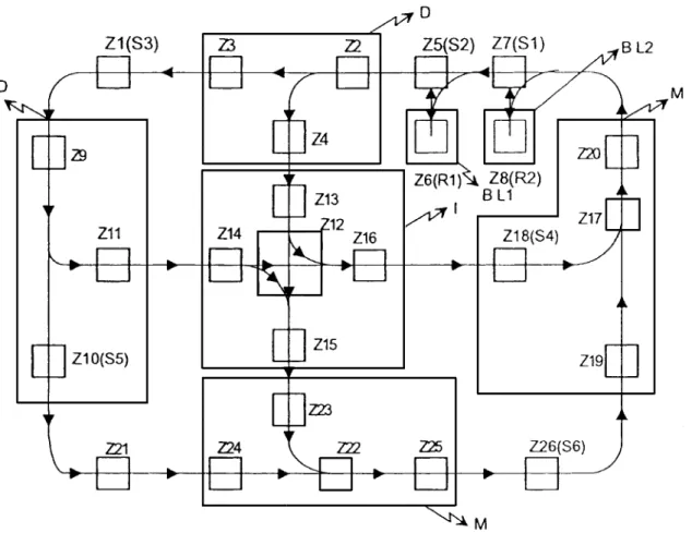
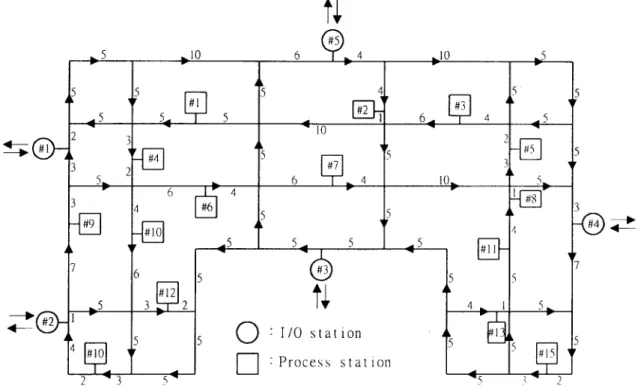
A sm all m an ufacturin g plan ( Hsieh an d Sh ih 1994) is taken as an e xam ple to sh ow th e e ffe ctive n e ss of th e propose d m e thod in this se ction . A m ore soph isticate d case ( Srinivasan et al. 1994) will be give n in the n ext se ction for com parative study. Th e floor-p ath layout of th e sm all m an ufacturin g plan t is give n in figure 4. Th e figure gives two D n e ts, two M n e ts, one I ne t, two BL ne ts and se ve ral un m arke d n ets th at are L n ets. Th ere are 26 zon e s, Z1± Z26, in th e system . Stations S1± S6are
located at Z7, Z5, Z1, Z18, Z10, an d Z26, re spe ctive ly. Th e
re st areas R1 an d R2 of th e ve hicle are locate d at Z6
an d Z8, re sp e ctive ly. Th e syste m is m ode lle d as
follows.
1. Specify the m odule s of a give n floor-path layout, an d ge n e rate th e com ple te floor-path PN. 2. Specify station -zone place s, Z7, Z5, Z1, Z18, Z10an d
Z26, an d re place th e m by m acro place s.
3. Specify ve hicle num be rs, job type s, job sch e dules, zon e distance, veh icle ve locity, loadin g
/
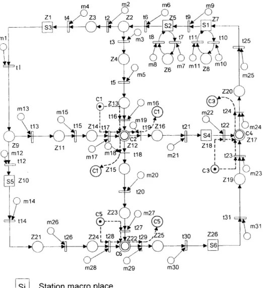
unloading tim e , m ach in e p roce ss tim e , d e te rm in istic or stochastic transition tim e, e tc.4. Construct and display floor-le ve l CP-CTPN, as shown in figure 5.
5. Specifiy m an age m en t policy an d gen e rate dis-patch in g an d route in g rule s to in te rface with th e m ode l via com m and place s.
6. Ge n erate coloure d in cide n t m atrice s, as shown in Figure 6, an d com pute m arking e volution. 7. Save anim ate d graphs an d sim ulation re sults.
Th e re sultin g floor-le ve l CTPN is give n in figure 5. It is note d that all transitions in th e system are tim e d e xce pt t16, t17, t22, t23, t27 an d t28. The se e xce ption al
transitions are control transition s th at h ave noth ing to do with ph ysical zon es. Z7, Z5, Z1, Z18, Z10and Z26are
station -zon e m acro place s. C1, C2, C3, C4, C5an d C6are
con trol place s. C2, C4 and C6 are supe rim pose d with
pse udo-zone or com posite -pse udo-zone place s ( Hsie h an d Sh ih 1992) Z12, Z17 an d Z22. Toke n s in e ach
con trol-loop place are zon e -con trol signals. Places m1±
m31 are com m an d place s that com m and the veh icle to
m ove . It is n ote d that the com m and place s, mi, are
num be re d after that of th e transition s. Th is is because th e m ain fun ction of the com m and place is to turn th e transition on an d off, and th e re fore , the com m an d place is associated with th e transition.
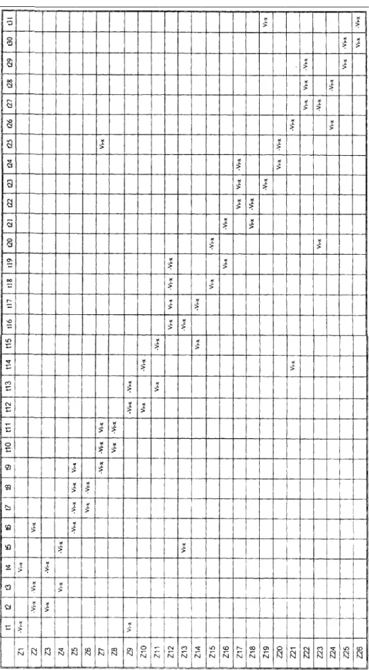
Figure 6 shows the colou re d in ciden t m atrix of th e m od e l. Th e fun ction al value of e ach e le m e n t in incide nt m atrix repre se n ts the status of th e veh icle in th e system . Blan ks th at appe ar in figure 6 in dicate th at no direct re lation e xists be twe e n th e transition an d th e place . It is n ote worth y that the re e xists on e pair of n on -ze ro elem e n ts in e ach transition . Th is im plie s th at e ve ry
veh icle will e ve n tually le ave the place som e tim e after it e n te rs the place .
7. Nu m e rical sim u lation an d co m p arison
A floor-path layou t ( Srin ivasan et al. 1994) is e m ploye d to ge n erate th e CP-CTPN m ode l for sim ula-tion by using th e propose d m e thod. Th e floor-path layout for n um e rical e xpe rim e nt is give n in figure 7. Since th e m odellin g proce dure is te dious an d th e re sulting m ode l is com plicate d, it will n ot be pre se n te d h e re . Howe ve r, th e sim ulation re sults are prese n te d in table 1, wh e re
a
f,a
e,a
1an da
brepre se n t th e fractions oftim e th at are re quire d by a ve hicle workin g in four diffe ren t conditions, nam e ly, travellin g loade d, travel-ling un loaded, waitin g in an idle state, an d blocking
F ig u re 6 . T h e colo u re d in ci d en t ma tr ix o f th e zo n e-pla ce p o rt io n .
T a b le 1 . S im u la ti o n re su lt s o f th e fo u r ve h ic le d is p a tc h in g ru le s fr o m th e C P -C T P N m o d e l. F C F S M F C F S S T T F M O D F C F S T h ro u g h -p u t N o . o f ve h ic le s af ae al ab O ve ra ll m e a n w a it in g ti m e af ae al ab O ve ra ll m e a n w ai ti n g ti m e af ae al ab O ve ra ll m e a n w a it in g ti m e af ae al ab O ve ra ll m e a n w a it in g ti m e D A T 1 D A T 2 D A T 3 8 8 8 0 .2 3 6 0 .3 3 5 0 .4 7 2 0 .2 0 9 0 .2 9 8 0 .4 2 1 0 .5 5 5 0 .3 6 7 0 .1 0 7 0 .0 1 8 8 0 .0 3 1 5 0 .0 4 9 4 1 .5 6 8 1 .7 6 2 4 .8 7 2 0 .2 3 1 0 .3 4 5 0 .4 7 1 0 .2 0 6 0 .3 0 6 0 .4 1 9 0 .5 6 3 0 .3 5 0 0 .1 0 3 0 .0 1 8 7 0 .0 3 2 4 0 .0 4 9 3 1 .5 5 5 1 .7 9 2 5 .1 9 2 0 .2 3 5 0 .3 3 9 0 .4 7 7 0 .2 0 8 0 .2 8 7 0 .3 3 8 0 .5 5 7 0 .3 7 5 0 .1 8 7 0 .0 1 8 8 0 .0 3 1 2 0 .0 4 6 2 1 .5 5 0 1 .6 2 2 1 .8 5 3 0 .2 3 3 0 .3 3 1 0 .4 7 6 0 .2 0 7 0 .2 8 8 0 .3 7 1 0 .5 6 0 0 .3 8 1 0 .1 5 3 0 .0 1 8 7 0 .0 3 1 1 0 .0 4 8 9 1 .5 6 3 1 .7 0 7 2 .4 8 7 T a b le 2 . S im u la ti o n re su lt s o f th e fo u r ve h ic le d is p at ch in g ru le s fr o m th e p a p e r o f S ri n iv as a n et a l. 1 9 9 4 (N / A m e a n s `n o t a va il a b le ’, S ri n va sa n et a l. d o n o t c o n si d e ve h ic le b lo ck in g ti m e ). F C F S M F C F S S T T F M O D F C F S T h ro u g h -p u t N o . o f ve h ic le s af ae al ab O ve ra ll m e a n w a it in g ti m e af ae al ab O ve ra ll m e a n w a it in g ti m e af ae al ab O ve ra ll m e a n w a it in g ti m e af ae al ab O ve ra m e a n w a it in g ti m e D A T 1 D A T 2 D A T 3 8 8 8 0 .2 2 0 0 .3 1 5 0 .4 4 3 0 .1 9 3 0 .2 7 6 0 .3 8 9 0 .5 8 7 0 .4 0 9 0 .1 6 8 N/ A 1 .4 1 0 1 .4 8 1 2 .1 7 6 0 .2 2 0 0 .3 1 5 0 .4 4 3 0 .1 9 3 0 .2 7 7 0 .3 9 0 0 .5 8 7 0 .4 0 8 0 .1 6 7 N/ A 1 .4 1 0 1 .4 8 4 2 .1 7 7 0 .2 2 0 0 .3 1 5 0 .4 4 3 0 .1 9 2 0 .2 7 1 0 .3 4 7 0 .5 8 8 0 .4 1 4 0 .2 1 0 N/ A 1 .4 0 5 1 .4 4 2 1 .5 6 7 0 .2 2 0 0 .3 1 5 0 .4 4 3 0 .1 9 3 0 .2 7 4 0 .3 6 8 0 .5 8 7 0 .4 1 0 0 .1 8 9 N/ A 1 .3 3 6 1 .3 6 5 1 .6 7 0
durin g travelling. For com parison purpose th e sim ula-tion results of Srinivasan et al. ( 1994) are liste d in table 2. It is n oteworth y that both fraction s of tim e com pute d by th e propose d m eth od for a ve hicle travelling loade d an d unloade d are h igh e r than those of Srin ivasan’ s. Th is is be cause th e detaile d fun ction s of zon e con trol an d ve hicle blocking are inclu de d in the pre se n t m ode l. Th e re fore , th e m ean waitin g tim e obtaine d by th e pre se n t m e th od is som e wh at h igh e r th an th at of Srin ivasan’ s.
8. Co nclu sio ns
Th is pape r prese n ts a m ode llin g m e thod to auto-m atically con struct an d solve an AGVS floor-leve l auto-m ode l usin g a give n floor-path layout. The ph ysical activity of th e AGVS is m ode lle d by CPNs, wh ile th e system pe rform an ce m easure is m odelle d by TPNs. In th e proce ss of de ve loping th e AGVS m ode l, a com puteraide d e nviron m en t was e stablish e d. In th e en viron -m e n t, th e AGVS floor-le ve l -m od e l an d colou re d incide nt m atrice s are con structe d system atically with m any de taile d fe ature s th at are not available in m ost gen e ral-purpose com m ercial program m es. By e m ploy-ing th e m ode l, one can evaluate the design altern atives of an AGVS quickly and re liably. Th e m odular m ode l con ce p t is e x te n d e d to bu ild c olou re d in cid e n t
m atrice s. Th e colou re d in cide n t su b-m atrice s for diffe ren t floorpath subn ets are de ve lope d. Th e com -p le te colou re d in cide n t m atrix for an AGVS can gen e rally be con structe d by th e de ve lope d com pute r program m e . Two e xam ple s are pre se n te d to validate th e propose d m e th od. Furthe r study on de ve lopin g a top-le ve l AGVS m an agem e nt m odel is n ow in progre ss.
References
EGBELU, P. J., 1984, Th e use of non-simulation approache s in estimating ve hicle re quire m e nts in an autom ate d guide d ve hicle base d tran sport syste m . Material Flow, 4, 17 ± 32. EGBELU, P. J. and TANCHO CO, J., 1984, Characte rization of
autom ated guide d ve hicle dispatch ing rule s. In tern ational
Jou rn al of Production Research, 22, 359 ± 374.
GASKINS, R. J. and TANCH O CO, J. M. A., 1987, Flow path de sign for autom ated guide d ve hicle syste m s. In ternational Jou rnal of
Produ ction Research, 25, 667 ± 676.
GASKINS, R. J. and TANCHO CO, J. M. A., 1989, AGVSim2, a de ve lopm e nt tool for AGVS con troller de sign. In tern ational
Jou rn al of Production Research, 27, 915 ± 926.
GENRICH, H. J. and LAUTENBACH, K., 1981, Syste m mode llin g with high-le ve l Pe tri nets. Theoretical Computer Scien ce, 13, 109 ± 136.
GO ETZ, W. G. an d EGBELU, P. J., 1990, Guide path de sign and location of load pick-up/drop -off poin ts for an autom ated guided ve hicle system . In ternational Journ al of Produ ction
Research, 28, 927 ± 941.
HO DGSO N, T. J., KING, R. E., MO NTEITH, S. K. and SCHULTZ, S. R., 1987, De veloping con trol rules for an AGVS usin g m arkov de cision proce sse s. Material Flow, 4, 85 ± 96.
HSIEH, S. and LIN, K.-H. M., 1991, Bu ilding AGV traffic-control m odels with place -transition ne ts. Intern ational Jou rn al of
Advanced Manu facturin g Techn ology, 6, 346 ± 363.
HSIEH, S. and SHIH, Y.-J., 1992, Autom ated guide d ve hicle system s and th eir Pe tri-ne t prope rties. Jou rn al of In telligen t
Man ufacturing, 3, 379 ± 390.
HSIEH, S. and SH IH, Y.-J., 1994, Th e deve lopm ent of an AGVS m odel by the union of the m odu lise d floor-path ne ts.
In tern ation al Jou rn al of Advanced Man ufacturing Techn ology, 9,
20 ± 34.
JENSEN, K., 1981, Coloured Pe tri n e ts an d the invariant m ethod. Theoretical Computer Scien ce, 14, 317 ± 336.
JENSEN, K., 1983, High-le ve l Pe tri nets. Applications an d Theory of
Petri Nets, A. Pagn on i and G. Roze nberg ( e ds) , In formatik-Fachberchte, 66, 166 ± 180.
KASPI, M. and TANCHO CO, J. M. A., 1990, O ptim al flow path de sign of unidire ctional AGV syste m s. In ternational Jou rn al of
Produ ction Research. 28, 1023 ± 1030.
KIM, Y.-D., 1990, A com parison of dispatching rule s for job shops with m ultiple ide ntical jobs and alte rnative route ings.
In tern ation al Journal of Produ ction Research, 28, 953 ± 962.
LIN, J. T., 1990, Dete rm ine how m any AGVs are nee de d.
In dustrial Engineering, 22, 53 ± 56.
MAXWELL, W. L. and MUCKSTADT, J. M., 1982, De sign of autom ate d guided ve hicle syste m s. IIE Transactions, 14, 114 ± 124.
MO LLO Y, M. K., 1982, Pe rformance analysis using stochastic Pe tri ne ts. IEEE Tran sactions on Computers, 31, 913 ± 917.
NATKIN, S., 1980, Les reseau x de Petri stochastiques et leu r
application a imath’evaluation des systems in formatiques, Ph .D.
Disse rtation ( in Fren ch) , CNAM, Paris.
NEWTO N, D., 1985, Simulation m ode l calculate s how m any autom ated guide d ve hicle s are n ee de d. Indu strial
Engineer-ing, 17, 68 ± 78.
RAMAMO O RTH Y, C. V. an d HO, G. S., 1980, Pe rform ance evaluation of asynchronous con current syste m s using Pe tri ne ts. IEEE Transactions on Software En gin eerin g, 5, 440 ± 449. RAMCHADANI, C., 1973, An alysis of Asyn chronous Concu rren t Systems
by Timed Petri Nets, Ph .D. Disse rtion, MIT, Cam bridge,
Massach use tts.
SIFAKIS, J., 1977, Use of Pe tri ne ts for pe rformance e valuation.
Measu rin g, Modellin g an d Evalu ating Computer System, H.
Be ilne r an d H. Ge le nbe ( e ds) , North-Holland, pp. 75 ± 93. SRINIVASAN, M. M., BO ZER, Y. A. and CHO, M., 1994, Trip-base d m ate rial handling syste m s: throughout capacity analysis. IIE
Transactions, 26, 70 ± 88.
TANCHO CO, J. M. A., EGBELU, P. J. an d TAGHABO NI, F., 1987, De term ination of the total num be r of vehicles in an AGV-base d m aterial transport syste m. Material Flow. 4, 33 ± 51. VENKATARAMANAN, M. A. and WILSO N, K. A., 1991. A
branch-and-boun d algorithm for flow-path de sign of autom ated guide d ve hicle syste m s. Naval Research Logistics, 38, 431 ± 445. VISWANADHAM, N. and NARAHARI, Y., 1992, Performance Modelling of
Au tomated Man ufacturing Systems ( Pre ntice Hall Inc., En gle
-wood Cliffs, New Jerse y) .
YIM, D.-D. and LINN, R. J., 1993, Pu sh an d pull rule s for dispatch in g autom ate d guide d ve h icle s in a fle xible m an ufacturing syste m . In ternational Journal of Produ ction