Tunable slow light device using quantum dot
semiconductor laser
P. C. Peng
Department of Applied Materials and Optoelectronic Engineering, National Chi Nan University, Nantou Hsien, Taiwan, R.O.C.
pcpeng@ncnu.edu.tw
C. T. Lin, H. C. Kuo, W. K. Tsai, J. N. Liu, S. Chi, and S. C. Wang Department of Photonics and Institute of Electro-Optical Engineering,
National Chiao Tung University, Hsinchu, Taiwan, R.O.C. hckuo@faculty.nctu.edu.tw
G. Lin, H. P. Yang, K. F. Lin, and J. Y. Chi
Opto-Electronics and System Laboratory, Industrial Technology Research Institute, Hsinchu, Taiwan, R.O.C. Abstract: This investigation experimentally demonstrates a tunable slow light device using a quantum dot (QD) semiconductor laser. The QD semiconductor laser at 1.3 μm fabricated on a GaAs substrate is grown by molecular beam epitaxy. Tunable slow light can be achieved by adjusting the bias current and wavelength detuning. The slow light device operated under probe signal from 5 to 10 GHz is presented. Moreover, we also demonstrate that the tunable slow light device can be used in a subcarrier multiplexed system.
©2006 Optical Society of America
OCIS codes: (140.5960) semiconductor lasers; (230.1150) Optical devices: All-optical devices.
References and links
1. R. W. Boyd, D. J. Gauthier, and A. L. Gaeta, "Applications of slow light in telecommunications," Optics & Photonics News 19, 18-23 (2006).
2. L. V. Hau, S. E. Harris, Z. Dutton, and C. H. Behroozi, "Light speed reduction to 17 m/s in an ultracold atomic gas," Nature 397, 594-598 (1999).
3. M. S. Bigelow, N. N. Lepeshkin, and R. W. Boyd, "Superluminal and Slow-light propagation in a room-temperature solid," Science 301, 200-202 (2003).
4. Y. Okawachi, M. S. Bigelow, J. E. Sharping, Z. M. Zhu, A. Schweinsberg, D. J. Gauthier, R. W. Boyd, and A. L. Gaeta, "Tunable all-optical delays via Brillouin slow light in an optical fiber," Phys. Rev. Lett. 94, 153902 (2005).
5. K. Y. Song, K. S. Abedin, K. Hotate, M. González Herráez, and L. Thévenaz, "Highly efficient Brillouin slow and fast light using As2Se3 chalcogenide fiber," Opt. Express 14, 5860-5865 (2006).
6. J. E. Sharping, Y. Okawachi, and A. L. Gaeta, "Wide bandwidth slow light using a Raman fiber amplifier," Opt. Express 13, 6092-6098 (2005).
7. D. Dahan and G. Eisenstein, "Tunable all optical delay via slow and fast light propagation in a Raman assisted fiber optical parametric amplifier: a route to all optical buffering," Opt. Express 13, 6234-6249 (2005).
8. P. C. Ku, F. Sedgwick, C. J. Chang-Hasnain, P. Palinginis, T. Li, H. Wang, S. W. Chang, and S. L. Chuang, "Slow light in semiconductor quantum wells," Opt. Lett. 29, 2291-2293 (2004).
9. X. Zhao, P. Palinginis, B. Pesala, C. J. Chang-Hasnain, and P. Hemmer, "Tunable ultraslow light in vertical-cavity surface-emitting laser amplifier," Opt. Express 13, 7899-7904 (2005).
10. H. Su, P. Kondratko, and S. L. Chuang, "Variable optical delay using population oscillation and four-wave-mixing in semiconductor optical amplifiers," Opt. Express 14, 4800-4807 (2006).
11. H. Su and S. L. Chuang, "Room-temperature slow light with semiconductor quantum-dot devices," Opt. Lett. 31, 271-273 (2006).
12. H. Su, and S. L. Chuang, "Room temperature slow and fast light in quantum-dot semiconductor optical amplifiers," Applied Physics Letters 88, Art. No. 061102 (2006).
13. D. Bimberg, “Quantum dots for lasers, amplifiers and computing,” Journal of Physics D: Applied Physics 38, 2055-2058 (2005).
14. N. N. Ledentsov, "Long-wavelength quantum-dot lasers on GaAs substrates: from media to device concepts," IEEE Journal of Selected Topics in Quantum Electronics 8, 1015 - 1024 (2002).
15. V. M. Ustinov , N. A. Maleev, A. R. Kovsh, and A. E. Zhukov, "Quantum dot VCSELs," Physica Status Solidi A 202, 396-402 (2005).
16. H. P. Yang, Y. H. Chang, F. I. Lai, H. C. Yu, Y. J. Hsu, G. Lin, R. S. Hsiao, H. C. Kuo, S. C. Wang, and J. Y. Chi, "Singlemode InAs quantum dot photonic crystal VCSELs," Electronics Letters 41, 1130-1132 (2005).
17. Y. H. Chang, P. C. Peng, W. K. Tsai, G. Lin, F. I. Lai, R. S. Hsiao, H. P. Yang, H. C. Yu, K. F. Lin, J. Y. Chi, S. C. Wang, and H. C. Kuo, "Singlemode monolithic quantum-dot VCSEL in 1.3 μm with side-mode suppression ratio over 30dB," IEEE Photonics Technology Letters 18, 847-849 (2006).
18. I. Kaminow and T. Li, Optical Fiber Telecommunications IVB (Academic Press, San Diego, 2002), Chap. 15.
19. O. H. Adamczyk, A. B. Sahin, Y. Qian, S. Lee, and A. E. Willner, "Statistics of PMD-induced power fading for intensity-modulated double-sideband and single-sideband microwave and millimeter-wave signals," IEEE Transactions on Microwave Theory and Techniques 49, 1962-1967 (2001).
20. H. Y. Pua, K. Peddanarappagari, B. Zhu, C. Allen, K. Demarest, and R. Hui, "An adaptive first-order polarization-mode dispersion compensation system aided by polarization scrambling: Theory and demonstration," Journal of Lightwave Technology 18, 832-841 (2000).
1. Introduction
Slow and fast light has attracted a lot of attention because it has significant applications in optical communication, optical memories, signal processing, and phase-array antenna systems [1-7]. Recently, slow light has been demonstrated in electromagnetically induced transparency, coherent population oscillations, and stimulated Brillouin and Raman scattering. The slow light based on semiconductor optoelectronic devices is also promising due to its inherent compactness, direct electrical controllability, and low power consumption [8-12]. Moreover, room temperature slow light in a quantum dot (QD) semiconductor optical amplifier has been recently demonstrated because quantum dots can provide better carrier confinement and offer reduced thermal ionization or carrier escape at room temperature [11-12]. Therefore, the quantum dot gain medium is attractive compared with bulk and quantum wells. Semiconductor lasers with the quantum dot gain medium also have been studied to improve the laser characteristics, including low threshold currents, temperature insensitive, low chirp, and high differential gain [13-17]. Long-wavelength QD vertical-cavity surface-emitting laser (VCSELs) using intracavity structures have been proposed [14-15]. However, the fabrication method of intracavity structures is critical and the device yields are low. Recently, there has been significant progress in the development of monolithically single-mode QD VCSELs [16-17].
In this paper, we report the slow light device using the monolithically single-mode QD VCSEL in an external injection scheme. Tunable slow light can be achieved by adjusting the bias current and wavelength detuning. A 10 GHz modulation signal with optical group delay 95 ps is presented. We also study the relationship between the modulation frequencies of probe signal and the time delay. The slow light device can be used in a subcarrier multiplexed (SCM) system.
2. Experiment and Results
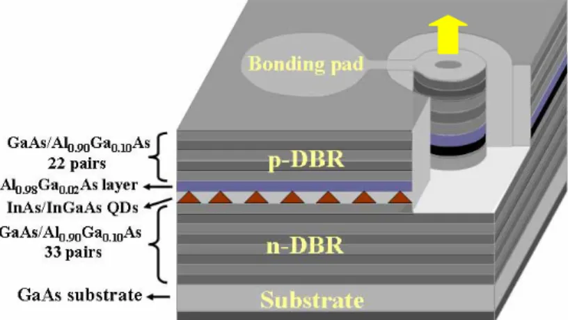
The schematic diagram of the monolithically single-mode QD VCSEL is shown in Fig. 1. The structure is grown on a GaAs (100) substrate by molecular beam epitaxy (MBE). The p- and n-doped distributed Bragg reflectors (DBRs) are composed of 22 and 33.5 periods, respectively. The graded-index separate confinement heterostructure active region mainly consist of five groups of QDs active region embedded between two linear-graded AlxGa1-xAs (x = 0 to 0.9 and x = 0.9 to 0) confinement layers. Each group of QDs consists of three QD layers and is situated around the antinode of a standing wave. The thickness of the cavity active region is about 1.13μm. The fabrication method has been described in our previous works [17]. In addition, the monolithically single-mode QD VCSEL is hermetically sealed by
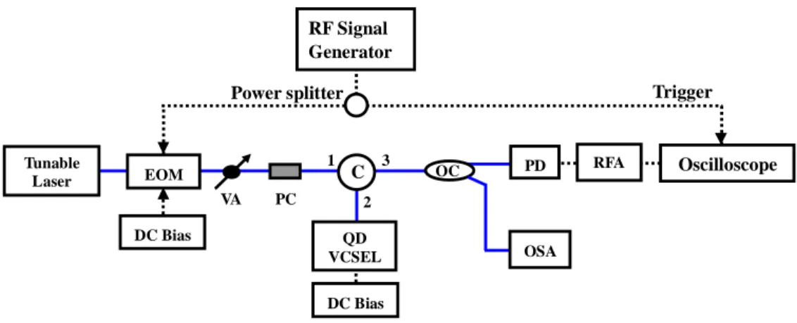
QD VCSEL Lens Fiber a standard TO-Can package with a built-in lens. The TO-Can packaged QD VCSEL and the single-mode fiber are assembled by laser welding technique, as shown in Fig. 2. Fig. 3 shows the output spectrum and light-current characteristics of the QD VCSEL. The threshold current is about 0.7 mA (Ith= 0.7 mA), and the lasing wavelength of QD VCSEL is around 1277.1 nm. Fig. 4 shows the experimental setup for measuring the slow light in the QD VCSEL. A probe signal is generated by a tunable laser and than modulated via an electro-optical modulator (EOM). The signal power is controlled by a variable optical attenuator (VA) at the output of the electro-optical modulator. The polarization of the probe signal is adjusted by a polarization controller (PC) to reach the maximum time delay in the QD VCSEL. An optical circulator (C) is used to couple the probe signal into the QD VCSEL. Fig. 5 shows the measurements of time delay for a 10 GHz probe signal at the various bias currents of QD VCSEL. The probe signal is tuned to the resonance of the QD VCSEL cavity, and the signal power is -14 dBm. Increasing the bias current of QD VCSEL can increase the time delay of probe signal. The maximum group delay of 42 ps is observed, and the driving current is at 1 mA. Fig. 6 shows the measurements of time delay at the different wavelength detuning when the driving current is 1 mA. The optical delay can be achieved to 95 ps delay at the wavelength detuning 0.042 nm.
Fig.1. Schematic diagram of monolithically single-mode QD VCSEL.
1276 1277 1278 1279
Int
e
ns
it
y (10
d
B
/d
iv
.)
Wavelength (nm)
Fig. 3. Output spectrum and light-current characteristics of quantum dot VCSEL.
Oscilloscope Trigger RF Signal Generator C PD DC Bias PC Tunable Laser VA 1 2 3 RFA EOM DC Bias OC QD VCSEL Power splitter OSA
Fig. 4. Experimental setup for measuring the slow light in QD VCSEL. (EOM: electro-optic modulator, VA: variable optical attenuator, C: optical circulator, OC: optical coupler, PC: polarization controller, RFA: RF amplifier, PD: photodetector, OSA: optical spectrum analyzer)
Int ens it y ( a . u.) Time (20 ps / div.) 0.6 mA 0.7 mA 0.9 mA 1 mA Driving Current Ref.
Fig. 5. The measurements of time delay of QD VCSEL at the various bias currents.
Pow er (μ W) 0.0 0.3 0.6 0.9 1.2 -2 0 2 4 6 8 10
Bias Current (mA) Ith= 0.7 mA
4 5 6 7 8 9 10 11 20 30 40 50 60 70 80 De al y ( p s) Modulation Frequency (GHz) In tensi ty (a. u. ) Driving Current 1 mA Time (20 ps / div.) Wavelength Detuning 0 nm 0.09 nm 0.06 nm 0.042 nm Ref.
Fig. 6. The measurements of time delay at different wavelength detuning.
8 GHz Inte ns ity (a . u. ) Time (20 ps / div.) Ref. 1 mA 1 mA In te nsi ty (a . u.) 6 GHz Ref. Time (50 ps / div.) △ T = 44 ps △ T = 60 ps
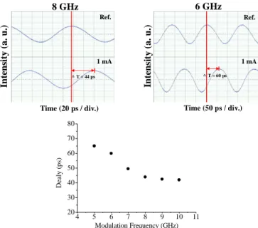
Fig. 7. The waveform of probe signals at different modulation frequencies.
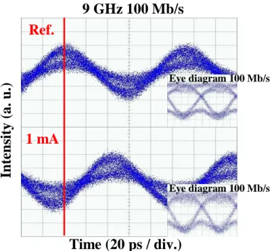
Figure 7 shows the waveform at different modulation frequencies of probe signals when the bias current of QD VCSEL is at 1 mA and the wavelength detuning is 0 nm. For 8 GHz and 6 GHz, the time delays are 44 ps and 60 ps, respectively. Moreover, the relationship between the time delays and modulation frequencies of probe signal are shown in the inset of Fig. 7. The time delay in the QD VCSEL increases as the modulation frequency decreases. We also demonstrate that this slow light device can be used for SCM systems. Figure 8 shows the experimental setup for the slow light device in a SCM system. A 100 Mb/s non-return-to-zero (NRZ) pseudo-random binary sequence (PRBS) data with 231 – 1 pattern length from a pattern generator (PG) is mixed with a 9 GHz RF carrier. The electrical microwave signal is then used to modulate the electro-optic modulator. Fig. 9 shows the time domain measurements of the 9 GHz 100 Mb/s signal. The time delays are around 42.5 ps. Then, the 9 GHz 100 Mb/s is down converted using a mixer, where it is mixed with the same RF carrier generated by the signal
Intensity (a.
u
.)
generator. The corresponding eye diagrams are shown in the inset of Fig. 9. Measurements of eye diagrams indicate that the developed slow light device is appropriate for use in a 9 GHz 100 Mb/s SCM system. Oscilloscope RF Signal Generator C PD DC Bias PC Tunable Laser VA 1 2 3 RFA EOM DC Bias OC QD VCSEL OSA PG Mixer 100 Mb/s Trigger LPF Power splitter
Slow Light Device OA
Fig. 8. Experimental setup for the QD VCSEL in a subcarrier multiplexed system. (PG: pattern generator, LPF: low pass filter, OA: optical amplifier).
Fig. 9. 9 GHz 100 Mb/s data signal and eye diagram of 100 Mb/s signal from the oscilloscope.
SCM has many important applications in optical systems including: cable television systems, fiber-wireless systems, microwave photonics systems, and controlling information in optical networks. However, polarization-mode dispersion (PMD) is one of the critical challenges in long-distance optical transmission systems using SCM after the successful mitigation of chromatic dispersion. Although present-day fibers have PMD values ~ 0.1
Time (20 ps / div.)
Eye diagram 100 Mb/s Eye diagram 100 Mb/s9 GHz 100 Mb/s
Ref.
1 mA
ps/km1/2, much of the previously embedded fiber has PMD values ranging from 1 to as high as 10 ps/km1/2 [18, 19]. For SCM systems, when the relative propagation delay between the two orthogonal principal states of polarization of the fiber (i.e., first-order PMD) is the half of period of the subcarrier, a serious SCM signal fading occurs. Due to PMD varying with temperature and other environmental changes, a tunable optical delay is required to compensate the PMD [18, 20]. However, the tunable optical delay is often implemented by using a mechanical system. The speed and size of the mechanical system raise concerns. Therefore, the tunable slow light device based on semiconductor optoelectronic devices is promising due to inherent compactness and electrical controllability.
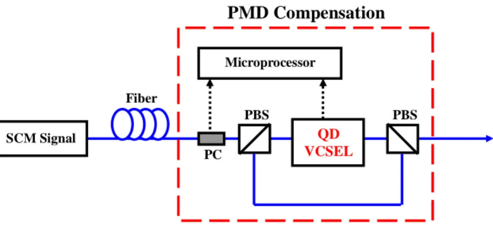
Using the tunable slow light device is possible for the PMD compensation in a SCM system, as shown in Fig. 10. A polarization beam splitter is used to separate the signal carrier by the two principal states of polarization. A polarization controller precedes the polarization beam splitter to align the two principal states of polarization with the principal axes of the polarization beam splitter. Following the polarization beam splitter is the slow light devices using the QD VCSEL to compensate for the link differential time delay. The two optical paths are recombined, and the effects of polarization-mode dispersion can be entirely compensated in the optical domain.
PC Fiber
PMD Compensation
SCM Signal QD VCSEL PBS PBS MicroprocessorFig. 10. Proposed architecture for the PMD compensation using a QD VCSEL. (SCM signal: subcarrier multiplexed signal, PBS: polarization beam splitter)
3. Conclusion
We experimentally demonstrate a tunable slow light device using a 1.3 μm QD VCSEL at room temperature for the first time. The monolithically single-mode QD VCSEL based on GaAs substrate is the fully doped structure. Optical delays 95 ps for 10 GHz are achieved by varying the bias current and wavelength detuning. Moreover, we also study that the relationship between the modulation frequency of probe signal and the time delay. The slow light device for a 9 GHz 100 Mb/s SCM system has been demonstrated. Additionally, a novel PMD compensating system using the tunable slow light device is also proposed. The idea has the potential to reduce the size and cost of the PMD compensator.
Acknowledgments
The authors would like to thank Dr. A. R. Kovsh (NL Nanosemiconductor GmbH) for his assistance and cooperation in epitaxial growth. This work is supported by the National Science Council, Republic of China, under contract NSC 94-2752-E-009-007-PAE and NSC 95-2112-M-260-001-MY2.