Proceedings of the 2000 IEEE International Conference on Robotics & Automation
San Francisco, CA April 2000
Modeling and Performance Evaluation of a Controlled IC Fab Using
Distributed Colored Timed Petri Net
Chung-Hsien Kuo
*
and Han-Pang Huang '*Robotics Laboratory, Department of Mechanical Engineering National Taiwan University, Taipei 10660, TAIWAN
Email: hphuangaw3 .me.ntu.edu.tw
TELRAX: (886)2-23 63 3 875 "Professor and correspondence address&
Abstract
This paper proposes the modeling and performance evaluation of a controlled IC foundry fab using a distributed colored timed Petri net (DCTPN). A DCTPN is designed for highly model-mixed and flexible routing manufacturing systems. The distributed models can be integrated through communication places, and the manufacturing execution system (MES) can be executed using a COM (component object model) server place. Especially, the process activities of a general IC foundry tools are analyzed, modeled and grouped into a basic tool model library. Based on the tool model library, an entire fab model can be constructed. The DCTPN-based fab model can act as a virtual fab, and be used to estimate fab performance and fab behaviors. In addition, the DCTPN conflict resolution and token competition rules are used to control a fab. Finally, a simplified 200" IC fab is presented and its system performance, including throughput, stage move, WIP (wafer in process) distribution, lot cycle time, utilization, is evaluated. The operation histories of tools and lots are also included. The entire fab model has been verified in a real IC foundry fab.
Keywords: distributed colored timed Petri net, IC foundry
fab, tool model library, fab performance
Introduction
IC foundry is one of the most important manufacturing systems in next generation. The process routing of an IC foundry is very complex and hundreds of operations are required. Besides, many different types of products are manufactured in a fab at the same time. This causes modeling difficulty for such a complex system. Typically, a fab is configured in terms of the plant, areas, tool groups and tools hierarchically. In order to increase the production efficiency, different types of products have to use the same tools. Hence, the resource sharing characteristics are important to the system. The fab behaviors can be characterized as concurrent operation, resource sharing, mutual exclusion, conflict, choice, product-mixes, parallel operation and sequential operation. In general, queuing theory, neural networks, finite-state machine and Petri Net (PN) [1, 5, 9-12, 191 can be used to model and analyze a manufacturing system. Among theses, a Petri net is powerful to model a system with concurrent and asynchronous properties [5, 181. Therefore, Petri net is selected here to model the IC foundry fab.
Due to the complex production routing of wafer lots and the highly product model mixes of the fab, it may need a very complex and huge ordinary Petri net. The complex net is hard to read and analyze. Because of these reasons, a distributed colored timed Petri net (DCTPN) [13, 141 is developed to simplify the complex model of the ordinary Petri net. The DCTPN adds color attributes, timed-based property, modular-based description [ 171 and
*Graduate student
communication-based connectivity among different nets to the ordinary Petri net. In addition, the Microsoft DCOM (distributed component object model) servers are embedded in the DCTPN to provide simulation and real- time control. It is designed for the requirements of modern manufacturing systems.
In this paper, the production of IC foundry is first introduced. The fab behaviors and tool types of an IC foundry fab are explored. The development of DCTPN is briefly described. The basic DCTPN tool model library can be constructed based on different types of IC foundry tool. Based on the tool model library, an entire fab DCTPN model can be constructed. The DCTPN-based fab model can act as a virtual fab, and be used to estimate fab performance and fab behavior. In addition, conflict transition resolution and token competition rules are important properties of the DCTPN. They can be used to model the dispatching rules of a fab. Hence, a controlled IC fab can be established. Finally, the system performance, including throughput, stage move, WIP (wafer in process) distribution, lot cycle time, utilization, is evaluated. An integrated DCTPN environment [4] is used to simulate distributed DCTPN models for analyzing detailed system behavior. The entire fab model has been verified in a real IC foundry fab.
IC Foundry Fab
An IC foundry fab can be characterized as complex production routes, highly product mixes and short lifecycle. It is a discrete event dynamical system [2]. Wafers are the material of the IC fab. They can be grouped into lots (e.g., a lot may contain 24 pieces of wafers). The wafers in a lot have the same process routes. In general, hundreds of operations must be completed for the lots. The operations of the wafer lots may contain oxidization, photo resistant coating, developing, etching, ion doping, chemical deposition, diffusion, implantation, etc. Equipment in an IC fab can be grouped into six functional areas: photo, sputter, CVD, implantation, etching and diffusion areas. Each functional area is composed of the corresponding functional equipment. In this paper, a fab is configured in terms of the plant, areas, tool groups and tools hierarchically, as shown in Fig. 1. They are described as follows:
1. Tool level: A tool is the basic element in the proposed fab architecture. The reliability and the utilization of a tool play important roles for the overall system performance.
2. Tool group level: A tool group is composed of several tools that have the same manufacturing purposes. The recipe (process route) is described as a series of prescribed operations. Normally, each prescribed operation is assigned to a tool group rather than a tool.
and the tool groups in an area have similar manufacturing fimction. When a lot enters an area, the area controller must assign a tool group for the lot
.
4. Plant: A plant is the highest level in a fab. It coordinatesand controls the operations of each area in a fab. The new order (wafer lot) release is important in the plant level since it provides the material input of the fab. In this paper, the order release is achieved by a DCOM- based DORS (distributed order release server).
Fig. 1 Hierarchical structure of an IC fab An IC fab has several important characteristics as listed below:
1. Resource sharing: In a fab, a tool does not belong to a specified product. A tool is dynamically assigned to different lots depending on the lot operation routes. 2. Concurrent and asynchronous operations: The lots in a
fab are operated concurrently and asynchronously. The relationships among their operations are hardly to describe with a prescribed tool sequence.
3. Reentry operations: Reentry is an important characteristic in an IC fab. The same tool group (operation) may be used more than once in a complete process route.
4. Product model mixes: In a fab, hundreds of different types of products are manufactured simultaneously. The correlation among different product types is hardly analyzed.
5. Flexible routes: Due to tool group configuration, a prescribed tool operation sequence is impossible. 6. Flexible lot sizes: The number of wafers of a lot is not
fixed to a number, say 24. The lot splitting and join can be happened in a fab.
7. CIM is important to handle the huge production information: The IC manufacturing information, including lot information, tool information, engineering information, etc., are very huge. In addition to a high efficiency MES (manufacturing execution system) database, the integration of manufacturing information and the data collection are also important.
Distributed Colored Timed Petri Net (DCTPN) A DCTPN is designed by inheriting the properties of
ordinary Petri net [ 5 , 181, and taking into account the requirements of the modern manufacturing systems. A DCTPN is defined as an eleven-tuple structure, DCTPN
= (P,, T,, Po, To, P,, pd, Tm, A , B, F, c) [13, 141, where P, is
a set of timed places; T, is a set of timed transitions; Po is a set of immediate places; To is a set of immediate transitions; P , is a set of communication places; Pd is a set of COM server places; T, is a set of macro transitions; A is a set of directed arcs; B is a set of inhibitor arcs; F is a set of interrupt arcs; C is the color set of transitions and places.
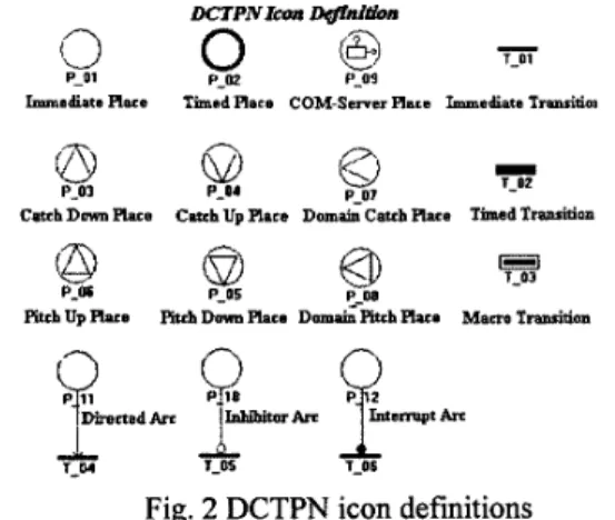
The DCTPN icon definitions are shown in Fig. 2. Notice that DCTPN is only briefly described in this section. The detailed definitions can be referred to [13, 141.
Immediate Race Timod Race COM-Serrer Rare Immsdkta T d m
8
-..z-
QLh
pth
1-w
Fig. 2 DCTPN icon definitions
In DCTPN, places are defined as: P =
{pl,p2,p3, ...,p n}. P is a finite set of places, n>l, including immediate, timed, COM server, and communication places. An immediate place is used to describe the state, condition or property (without time factor) of a resource. A timed place is used to describe the condition or property of a resource that requires elapsed time. A COM-server place is defined as a DCOM-based component server. When a token enters a COM server place, the corresponding remote server can be executed for serving the corresponding COM server place. In this paper, it acts as a MES server for releasing new order. Communication places provide the communication among different DCTPN nets. It includes domain-pitch, domain-catch, catch-up, catch-down, pitch- up and pitch-down places. Domain-pitch and Domain- catch places are used for the communication between different DCTPN nets at the same level. A domain-pitch place sends tokens to a corresponding domain-catch place at different net of the same level through the network. Pitch-up and catch-up places are used for the lower level DCTPN nets. Pitch-down and catch-down places are used for the higher level DCTPN nets. A pitch-up (pitch-down) place sends tokens to a corresponding catch-down (catch- up) place at the higher (lower) level net through the network.
Transitions are defined as: T = {tl,t2,t3,
...,
tm}. T i s afinite set of transitions, m>l, including immediate transitions, timed transitions and macro transitions. An immediate transition describes the events (without time factor) of a resource. A timed transition is used to describe the processes and events that need elapsed time of
resources. It fires only one token at each firing time. A macro transition can be used for net refinement. The interconnection between different and same levels is achieved by communication places.
Consequently, three types of arcs are defined in the DCTPN. A directed arc connects between a place and a transition, or vice versa. The place connected with an inhibitor arc is called an inhibitor place. When an inhibitor place contains the same color tokens as the output transition, then the output transition is inhibited to fire. Similarly, the place connected with an interrupt arc is called an interrupt place. When an interrupt place contains the same color tokens as the output transition, then the firing in the output transition is interrupted and further
inhibited. The color of the DCTPN represents the color sets of places and transitions. An arc multiplier is typically used to simplify the multiple arcs between a place and a transition. In a DCTPN, the arc multiplier can be a fixed value or a variable value depending on the color set. In addition, the colored marking, enabling and firing rules, time function, firing sequence, liveness and boundedness can be referred to [13].
The state machine and marked graph of the DCTPN is defined below. A state machine of the DCTPN is a distributed net that each transition in the net has exactly one input place and exactly one output place. A marked graph of the DCTPN is defined as that each place in the net has exactly one input transition and exactly one output transition. In this paper, the DCTPN transformations [I31 are proposed to simplify the complex DCTPN nets for structurally analysis.
ProDosition 1 :
A macro transition between a pitch-down and catch- down places pairs can be transformed into a timed A COM server place in DCTPN is equivalent to a timed A DCTPN transformation algorithm preserves the boundedness and liveness properties of the original DCTPN net.
The liveness of a state machine of the CTPN is
independent of color sets.
The liveness of a marked graph of the DCTPN is independent of time delays.
on 6 :
A DCTPN system is bounded i f f its supervisory and all
sub-nets are bounded.
Basic Tool Models of an IC Fab
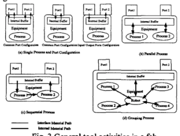
A tool (IC foundry equipment) is the basic element to configure a fab. In order to hierarchically construct a fab shown as Fig. 1, the commonly used basic tool models of the fab have to be constructed first to form a model library. In this manner, all tools can be constructed by inheriting the model library, and a complete fab model can be established in a precise way. The tool behaviors can be divided into the port and the process configurations. Fig. 3 shows several general tool activities in an IC fab. Fig. 3(a) indicates the single wafer process equipment with different port configurations. The “common ports configuration” means that a lot enters and exits a tool uses the same port. The “inputloutput ports configuration” means a lot enters a tool from an input port, and exits the tool from an output port. On the other hand, the “single lot (wafer) process” indicates that the tool processes only one lot (a piece of wafer) at a time. Notice that the port number can be one, two, or more. However, the ports appear in pairs whenever the “inputloutput ports” configuration is discussed. Fig. 3(b) shows a parallel process tool. In this configuration, the multiple processes are operated in parallel. Fig. 3(c) shows a sequential process tool. In this configuration, the multiple processes are operated sequentially. Fig. 3(d) shows a grouping process tool. In this configuration, the multiple processes are operated with a specified process route, depending on different product types.
In this paper, several different types of tool models
are constructed to form a model library. They are: (1)
single lot process with common ports configuration, (2)
single lot process with inputloutput ports configuration, (3)
single wafer process with common ports configuration, (4) single wafer process with inputloutput ports configuration,
( 5 ) batch lots process with inputloutput ports configuration, ( 6 ) parallel process with common ports configuration, (7)
parallel process with inputloutput ports configuration, (8) sequential process with inputloutput ports configuration, ( 9 ) route determined single wafer grouping process with input/ output ports configuration, and (10) route determined single wafer grouping process with common ports configuration.
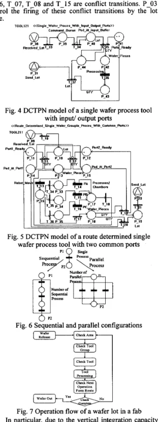
Fig. 3 General tool activities in a fab Fig. 4 shows a DCTPN model of a single wafer process tool with input/output ports. Fig. 5 shows a DCTPN mode1 of a route determined single wafer process tool with two common ports. PA, PB and PC are three process chambers. Notice that the single lot process tool model can be obtained by changing the variable arc multiplier, i.e. “QTY”, to a fixed value, say 1, in Fig. 4. In addition, if the sequential and the parallel processes are required, then they can be obtained by adding transitions and places in Fig. 4 to form the desired configurations. Fig. 6 shows that the adding transitions, arcs and places form a parallel or sequential process configuration. If the basic model library is constructed, then the entire system DCTPN models can be established from tool model to tool
group model, from tool group model to area model, and from area model to plant model.
Modeling an IC Fab Using Basic Tool Models
An IC foundry fab can be modeled in terms of Petri nets [S, 16, 201. In this section, the model of an IC fab is
constructed based on the model library illustrated in the previous section. Based on the hierarchical structure shown in Fig. 1, a hybrid modeling approach is used here. Both top-down and bottom-up (hybrid) approaches are used to accomplish the entire system model. The system model architecture can be constructed first by dividing the system into several hierarchies and modules. Consequently, the entire system can be established in terms of the inter- correlated sub-nets. All sub-nets communicate with each other in terms of the communication places. Before modeling the fab models, the operation flow of a wafer lot is discussed first. Fig. 7 shows the details.
The procedures and notations of modeling a manufacturing system using DCTPN can be referred to [ 13, 141. For simplicity, only the plant level DCTPN model is shown here. Fig. 8 shows the plant level DCTPN model. In this model, T-09, T-10 and T-11 are macro transitions,
they indicate “AREA l”, “AREA 2” and “AREA 3”,
respectively. P-06 to P-11 are communication places to form the interface of distributed area level models. Besides, T 0 6 , T-07, T-08 and T-15 are conflict transitions. P-03 control the firing of these conflict transitions by the lot route.
‘100~121 < < s i n ~ l e _ w s l c r _ t ’ r o c ~ ~ - ~ l h - l ” ~ ~ - O ~ “ l - r ~ ~ ~ ~ ~
P-31 Send-Lot
Fig. 4 DCTPN model of a single wafer process tool with input/ output ports
~<Rouie_Dcicrmlnrd Slngle Walrr~Groupln Roces. WII. Common_hm))
Fig. 5 DCTPN model of a route determined single wafer process tool with two common ports
Check Area
Fig. 6 Sequential and parallel configurations
Wlfcr Release Check Tool Roccssing Check Nut Form Route Check Wsfer ow omp1
Fig. 7 Operation flow of a wafer lot in a fab In particular, due to the vertical integration capacity with MES of DCTPN, the DCOM-based distributed order release server (DORS) can be integrated into the model. A
new order can be generated from the MES database in
terms of order release rules. P-02 is a DORS type COM- server dace.
Fig. 8 Plant level DCTPN model of a fab Controlled Fab Modeling
In a fab, the dynamic lot dispatching system [6] is critical to the fab performance. In this paper, the DCTPN conflict resolution and the token competition rules can be used to develop a controlled fab. In Fig. 9, the transitions of T1 and T2 are conflicted by P1. Only one of them can be fired at the same time. This is the conflict of DCTPN. On the other hand, there are 4 tokens in the place P2. The tokens compete with each other for releasing order. This is a DCTPN token competition problem.
The rules for resolving conflict transitions are: (1) select maximum fire count of conflict transitions; (2) select maximum fire time of conflict transitions; (3) select maximum queue length of conflict transitions; (4) select minimum fire count of conflict transitions; (5) select minimum fire time of conflict transitions; (6) select minimum queue length of conflict transitions; (7) select maximum priority of conflict transitions; (8) random selection of conflict transitions; (9) sequential selection of conflict transitions; (10) select one from conflict transitions by referring to transition name and a token specified attribute; (1 1) select a meaningful token for the higher priority transition, and a non-meaningful token for the lower priority transition.
q n
9:
Campetrtlon of TokenL T I
Gmtl~u 0fTmauuws
Fig. 9 Conflict between transitions and token competition in a place
In addition, the rules for resolving token competition problem are: (1) first come first serve of tokens; (2)
random selection of tokens; (3) select from the tokens’ priority attributes; (4) last come first serve of tokens; ( 5 )
select fiom the tokens’ earliest commit due date attributes; (6) select from the tokens’ shortest processing time attributes; (7) select from the tokens’ weighted shortest processing time attributes; (8) select from the tokens’ shortest remaining processing time attributes; (9) select from the tokens’ longest remaining processing time attributes; (10) select from the tokens’ fewest operation remaining count attributes; (1 1) select from the tokens’ largest operation remaining count attributes; (12) select from the tokens’ earliest release time attributes; (1 3) select from the tokens’ latest release time attributes.
competition rules are applied to a fab DCTPN model, a fab can be controlled by the desired dispatching rules.
Fab Performance Evaluation
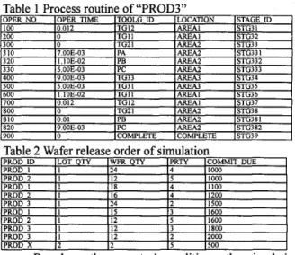
For simplicity, only three areas out of six areas of a real fab are considered in this paper. The configuration of the fab is shown in Fig. 10, where “TG” means the “tool group”. “TG11” is a single wafer process tool with two common ports. “TG12” and “TG33” are single wafer process tools with input/ output ports. “TG21” is a route determined single wafer grouping process tool with two common ports. “TG3 1” is a single wafer sequential process tool with input/ output ports. “TG32” is a single wafer parallel process tool with inpdoutput ports.
All models are constructed in terms of DCTPN integrated simulation environment [4, 71. The environment is a three-tier component-based architecture. Fig. 11 shows a distributed simulation and synchronization architecture of this paper. In this figure, the simulation center can synchronize distributed simulation clock and compensate the clock drift of distributed sites [3, 131. DCTPN inference engine is a DCOM-based DCTPN firing rules inference server. All distributed models communicate with each other through the communication places. Notice that the communication place is developed based upon NTU- NET [15]. NTU-NET is a real-time priority-based fault- tolerance communication protocol.
In order to examine the product mixes, flexible route and variable lot size (i.e., number of wafer pieces in a lot),
4 different types of products and 11 lots are used in this case. Each lot has different quantity of wafer pieces. Table 1 shows the process route of “PROD3” and Table 2 shows the wafer release order. The controlled fab model uses three different dispatching rules and order release rules to supervise the fab. They are: (1) Controll: First come first serve of waiting lots with new order releasing rule 1; (2) Control 2: Lot priority with new order releasing rule 1; (3) Control 3: Lot priority with new order releasing rule 2.
AREA2
-
TO21Fig. 10 A simple fab configuration
DCrPN Cammpuication WE” Model Place Model
Fig. 11 Distributed simulation and synchronization architecture
The “new order releasing rule 1” releases a new order by checking the control policies of “Wafer-Quantity- >Lot-Quantity->Commit-Due -> Lot-Priority” (highest priority to lowest priority). Whereas “new order releasing rule 2” releases a new order by checking the control policies of “Lot-Priority -> Commit-Due-
> Wafer-Quantity->Lot-Quantity”.
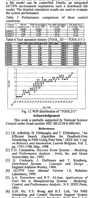
Based on three control conditions, the simulation results can be used to evaluate the fab performance. Table 3 shows their comparison of performance measurements. Table 4 shows the WAFER-START, WAFER-OUT and CYCLE times of three control conditions. Table 5 shows a lot operation history. Table 6 shows a tool operation history. From this table, the utilization of “TOOL1 11” is 53.71%. Finally, Fig. 12 shows the WIP (wafer in process) distribution of “TOOL2 1 1”.
Table 3 WAFER-START, WAFER-OUT and CYCLE times of three control conditions
Note: (I/ 2/ 3) indicate the measurements of condition 1,2 and 3
Conclusion
This paper proposes a controlled IC fab model using DCTPN. Based on the DCTPN, the product-mixes and flexible route can be described. #en a new product is introduced or when the process route of a product is changed, the models do not need to be modified due to the resource-oriented modeling of manufacturing systems. In addition, all distributed models can be integrated horizontally and vertically through communication places. A COM-server place integrates the DCOM-based MES servers. These DCTPN properties enhance the modeling capacity of a manufacturing system. On the other hand, The IC foundry equipment is analyzed and modeled to form the basic tool model library. An entire fab model can be constructed based on the model library and the fab
hierarchical structure. Due to the conflict transition resolution rule and the token competition rules of DCTPN, a fab model can be controlled. Finally, an integrated DCTPN environment implements such a distributed fab model. The detailed simulation results are used to evaluate the system performance.
Table 5 Performance comparison of three control conditions Control Condition Control 1 Control 2 Control3
Fab all Fab lot throughput Fab wafer throughput Fab stage move
operation time (#. oflot/ 1000 (#. ofwafer/ 1000 (#. o f s t a g d IO00 (clock) clocks) clocks) clocks)
2348 4.685 63.46 34.50
2156 5.102 69 I I 37.57
2337 4 707 63.76 34.66
Table 6 Tool operation history (TOOL I D = 'TOOL1 1 1 ')
;=
i
I
,, .. . . .. . . . .. . . ... . . ... .. .... . . . ... ... . . ... . ... .
I
,s
REC-TIME
Fig. 12 WIP distribution of "TOOL21 1" Acknowledgement
This work is partially supported by National Science Council under Grant number NSC 88-221 8-E-002-003.
References
[l] I.B. Adballah, H. EIMaraghy and T. EIMekkawy, "An
Efficient Search Algorithm for Deadlock-Free Scheduling in FMS Using Petri Nets," IEEE I d . Conf: on Robotics and Automation, Leuven Belgium, Vol. 2, pp. 1793-1798, May, 1998.
[2] C.G. Cassandras, Discrete Event Systems - Modeling and Performance Analysis , Irwin, Inc. and Aksen Assocxiates, Inc., 1993.
[3] G. Coulouris, J. Dollimore and T. Kindberg,
Distributed Systems
-
Concepts and Design ,Eng1and:Addison-Wesley, 1994.
[4] DCTPN User Manual Version 1.0, Robotics
Laboratory, 1999.
[SI A.A. Desrochers and R.Y. AI-Jaw, Applications of
Petri Net in Manufacturing Systems
-
Modeling, Control, and Performance Analysis,
N.Y.:IEEE Press,1995.
[6] G.H. Hu, Y.S. Wong and H.T. Loh, "An FMS Scheduling and Control Decision Support System Based on Generalised Stochastic Petri Net." Intl. Journal of Advanced Manufacturing Technolob, Vol.
[7] H.P. Huang and Y.H. Tseng, "Modeling and Graphic
Simulator for Integrated Manufacturing Systems,"
10, pp. 52-58, 1995.
[SI M.D. Jeng, X. Xie and S.W. Chou, "Modeling, Qualitative Analysis, and Performance Evaluation of the Etching Area in a IC Wafer Fabrication System Using Petri Net," IEEE Trans. on Semiconductor Manufacturing, Vol. 1 1 , No. 3, pp. 358-373, 1998.
[9] M.D. Jeng, "A Petri Net Synthesis Theory for Modeling
Flexible Manufacturing Systems," IEEE Transaction on Systems, Man, and Cybernetics - Part B, Vol. 27, No. 2, pp. 169-183, April, 1997.
[lo] C.H. Kuo, H.P. Huang, K.C. Wei and S.S.H. Tang,
"System Modeling and Real-Time Simulator for Highly Model-Mixed Assembly Systems," ASME Journal of Manufacturing Science and Engineering,
[l 13 C.H. Kuo and H.P. Huang, Tolored Timed Petri Net
Based Statistical Process Control and Fault Diagnosis to Flexible Manufacturing Systems," IEEE Int. Conf: on Robotics and Automation, New Mexico, Vol. 4, pp.
2741-2746, April, 1997.
[12] C.H. Kuo, H.P. Huang and M.C. Yeh, "Object- Oriented Approach of MCTPN for Modelling Flexible Manufacturing Systems," Int. Journal of Advanced Manufacturing Technology, Vol. 14, pp. 737-749,
1998.
[13] C.H. Kuo, Development of Distributed Component
Based Manufacturing System Framework," Ph. D. Dissertation, Institute of Mechanical Engineering, National Taiwan University, 1999.
[ 141 C.H. Kuo and H.P. Huang, "Integrated Manufacturing System Modeling and Simulation By Using Distributed Colored Timed Petri Net," IEEE lntl. Con$ on Systems, Man, and Cybernetics, 1999.
[ 151 L.R. Lin and H.P. Huang, "Real-Time Networking for
the Implementation of CIM," Proc. Int. Conference on Automation Technology, Taiwan, Vol. 1, pp. 21-28,
1996.
Vol. 121, pp. 282-289, 1999.
161 S.Y. Lin and H.P. Huang, "Modeling and Emulation
of a Furance in IC Fab Based on Colored-Timed Petri Net," IEEE Trans. on Semiconductor Manufacturing,
171 S.S. Lu and H.P. Huang, "Modularization and
Properties of Flexible Manufacturing Systems," in Advances in Factories of the Future, CIM and Robotics (edited by M. Cotsafiis and F. Vemadat), Amsterdam: Elsevier, pp. 289-298, 1993.
181 T. Murata, "Petri nets: Properties, Analysis and
Applications," Proceedings of the IEEE, Vol. 77, No.
[19] N. Wu, "Necessary and Sufficient Conditions for
Deadlock-Free Operation in Flexible Manufacturing Systems Using a Colored Petri Net Model," IEEE Tram. on Svstems. Man. and Cvbernetics. Vol. 29.
Vol. 11, NO. 3, pp. 410-420, 1998.
4, pp. 541-580, 1989.
No. 2, pp. l$2-204,' 1999.'
[20] M.C. Zhou and M.D. Jeng, "Modeling, Analysis, Simulation. Scheduling. and Control of Semiconductor ManufacGng Systems: A Petri Net Approach," IEEE Tram. on Semiconductor Manufacturing, Vol. 1 1 , No.
3, pp. 333-357, 1998.
Intelligent Automati& and Sofr Computing, Vol. 1, pp.