Fuh-Kuo Chen
ProfessorCheng-Jun Chen
Graduate StudentDepartment of Mechanical Engineering, National Taiwan University, Taipei, Taiwan
On the Nonuniform Deformation
of the Cylinder Compression Test
A theoretical model based on Hill’s general method is developed in the present study to calculate the flow stress in a cylindrical specimen under axial compression in the pres-ence of friction at the die-specimen interface. Unlike most of the published methods which studied the incipient barreling only, the proposed theoretical model takes the barreled shape of the deforming specimen into account. In order to construct the stress-strain curve, the mean effective strain of the barreled specimen was also calculated on the basis of an assumed velocity field. As the present study shows, the proposed theoretical model provides good results, both in magnitude and in trend, for the prediction of flow stresses in the barreled specimen during the compression test.关S0094-4289共00兲00602-2兴1 Introduction
The cylinder compression test has been widely adopted for de-termining a material’s flow stress as a function of the strain during the compression of cylindrical specimens between two flat dies. If the friction is absent at the die-specimen interface, the deforma-tion in the cylinder is uniform and the free surface of the cylinder remains straight during the compression. Thus, the flow stress of the specimen is simply the value obtained by dividing the applied force共P兲 by the contact area of die-specimen interface 共A兲, and the effective strain is the same as the axial compressive strain given by ln(2Ho/2H), where 2H0 and 2H are the initial height
and the instantaneous height of the deforming specimen, respec-tively. In reality, due to the presence of friction at the die-specimen interface, the radial displacement of the material near the interface is restrained while the remaining portion of the speci-men bulges out changing the free surface into the form of a barrel. The barreled shape leads to an inhomogeneity of deformation, and therefore, the method used to calculate the flow stress and the effective strain for the uniformly deformed specimen is not applicable.
Many theoretical methods have been proposed to derive the flow stress for a barreled specimen. Siebel关1兴 assumed no barrel-ing and a low coefficient of friction, and derived a simple well-known formula for the relationship between the mean axial pres-sure acting at the die-specimen interface and the flow stress of the material under frictionless uniaxial compression. With the use of the upper-bound method, Avitzur 关2兴 has determined a relation-ship between the applied load and flow stress of the material for a cylinder under uniaxial compression with friction at the die-specimen interface. Later, Lee and Altan 关3兴 also proposed an upper-bound velocity field that considers bulging of the cylinder during the upsetting. They developed computer programs to de-termine the strain, strain-rate, velocity, and flow-stress distribu-tions. Although the previous works mentioned above have taken the effect of friction into consideration, the efforts were mainly focused on the incipient barreling of the free surface. In other words, the specimen with a straight free surface was used for the analysis, and no attempt was made to consider a barrel-shaped specimen for the analysis.
Since the compression load acting on any cross-sectional area of the barreled specimen has the same value, another way to cal-culate the flow stress of the specimen may rest on the analysis for the mean cross sectional area. Following this concept, a simple expression for the flow stress共Y兲 is therefore suggested as
Y⫽P A
¯, (1)
where A¯ is the mean cross-sectional area obtained by dividing the volume of the specimen (V) by the instantaneous height 2H of the specimen. This method is termed the ‘‘mean flow stress method’’ thereafter in this paper.
In 1983, Ettouney and Hardt 关4兴 extended the concept, which Bridgman关5兴 had developed for calculating the stress distribution at the neck of tensile specimen, to determine the flow stress of the barreled specimen. Considering the barreled shape in the analysis, they derived a formula of the following nature:
Y⫽共z兲m
再冋
1⫺ 2R R2册
• ln冋
1⫺R2 2R册冎
⫺1 , (2) where 共z兲m⫽ P R2 2,Y is the flow stress of the material under frictionless uniaxial compression, P is the compression load, R is the radius of the bulge curvature, and R2 is the maximum radius of the barreled
specimen, as shown in Fig. 1.
In the present study, a theoretical model based on Hill’s general method was developed to calculate the flow stress of the barrel-shaped specimen, which is compressed under frictional condition. In the theoretical model, the longitudinal nonuniformity was un-der investigation, and an expression for the flow stress in terms of the compression load and the geometric parameters defining the barreled specimen was obtained. Finite element simulations were also performed in the present study in order to validate the theo-retical calculation. The flow stresses calculated according to the proposed theoretical model are compared with the true flow stress and with those predicted by the Ettouney and Hardt’s formula 共termed the ‘‘E-H formula’’ for short兲, and the mean flow stress method, based on the compression loads and the geometric param-eters obtained from the finite element simulations.
It should be noted that the strain distribution of the barreled specimen is also not uniform and the effective strain cannot there-fore be determined explicitly. Nevertheless, the overall axial com-pressive strain has been commonly used by researchers, without proof, to approximately represent the effective strain. In the present study, an admissible velocity field was proposed to calcu-late the mean effective strain, and the detailed derivation is pre-sented following the calculation of the flow stress.
Contributed by the Materials Division for publication in the JOURNAL OFENGI -NEERINGMATERIALS ANDTECHNOLOGY. Manuscript received by the Materials Division October 6, 1998; revised manuscript received February 13, 1999. Associate Technical Editor: G. Ravichandran.
2 Calculation of the Flow Stress
In 1963, Hill关6兴 proposed a new method of analysis for metal-forming processes based on a variational principle. Although Hill believed that the proposed method comes close to the ideal, very few investigations on the method have appeared in the published literature. Among them, Lahoti and Kobayashi关7兴 carried out the analysis of ring compression with barreling, spread in Steckel rolling, and thickness change in tube sinking.
Hill’s method begins by selecting a class of velocity field vi
from which the best approximation will eventually be taken. The selected velocity field must satisfy all the kinematic conditions. However, the associated stress field in the deformation zone, which is determined according to the material constitutive law, will not generally satisfy all the static requirements. Hence, the selection criterion for the best approximating stress fieldi jmay
be considered as
冕
V i j wj xi dV⫽冕
SI jwjdS⫹冕
SC 关共nii兲nj⫹mklj兴wjdS (3)for a sufficiently wide subclass of virtual orthogonalizing motion wj, whereidenotes the surface traction computed from the
con-sidered approximating stress field i j, ni, and nj are the local
unit outward normals, ljis a unit tangent vector opposite in sense
to the relative velocity of sliding in the approximating field, and mk represents the constant frictional stress with 0⭐m⭐1, k being the shear yield stress. For metal-forming process, the surface S of the deforming zone usually consists of three distinct parts: SC is
the interface between the die and the workpiece; SFis the
uncon-strained surface; SI is the interface between the deforming zone
and the rigid zone. It is to be noted that use of the reverse of the virtual work-rate principle has been made to derive Eq.共3兲, and although the method is applicable to all types of friction, constant friction is adopted in Eq.共3兲 for simplicity.
In applying Eq. 共3兲, the orthogonalizing family wj must be
sufficiently wide and extensive to identify a single approximating velocity field in the particular class constructed for satisfying the kinematic conditions. Once the orthogonalizing family is chosen, the calculus of variations technique is applied to Eq.共3兲, treating wj as a variation parameter. This furnishes a system of
equilib-rium equations and boundary conditions, suited to the particular approximating class, allowing us to determine its best member 共Lahoti and Kobayashi 关7兴兲. The detailed description of the method can be found in共Hill 关6兴兲.
To facilitate the analysis, the following assumption are made:
1 The deforming material is isotropic and incompressible. 2 The elastic deformation is negligible, i.e., the material is
con-sidered as rigid-plastic.
Now, consider a barrel-shaped specimen under compression be-tween two flat dies which move toward each other with a unit speed at any stage of compression. The specimen has an instanta-neous height of 2H and a radius of R1at the die-specimen
inter-face, as shown in Fig. 1. Since the nonuniform deformation in the z-direction is our main concern, the selected velocity field must be a function of z. A simple velocity field representing the incipient barreling of the specimen has been shown by Kobayashi et al.关8兴 to be in the form
vr⫽ 1
2r⌽⬘共z兲, v⫽0, and vz⫽⫺⌽共z兲, (4)
where vr,v,vz are the velocities in the r, , and z directions,
respectively, the prime denotes differentiation,⌽ is a function that is sufficiently differentiable. The velocity field given in Eq. 共4兲 implies the incompressibility of material, while ⌽(z) ⫽⫺⌽(⫺z), ⌽(H)⫽⫺⌽(⫺H)⫽1 due to the symmetry with spect to the mid-plane and the velocity boundary conditions, re-spectively. It is reasonable to suppose that the velocity field given in Eq.共4兲 continues to hold during a finite compression of the barreled cylinder, and it is therefore adopted in the present study to calculate the flow stress for the barreled cylinder.
One way to choose the virtual orthogonalizing velocities is just to take the similar form as that given in Eq.共4兲, such as
wr⫽ 1
2r⬘共z兲, w⫽0, and wz⫽⫺共z兲, (5)
with(z)⫽⫺(⫺z).
Making use of the following conditions: SI⫽0, 兵nr,n,nz其
⫽兵0,0,1其, and兵lr,l,lz其⫽兵⫺1,0,0其, Eq.共3兲 can be written as
2
冕
0 H再
冕
A冋
r wr r ⫹ wr r ⫹z wz z ⫹rz冉
wr z ⫹ wz r冊册
dA冎
dz ⫽2冕
A 关zwz⫺mkwr兴z⫽HdA, (6)noting that nj and li are the unit normal vectors in the z and r
directions, respectively.
Substituting Eq.共5兲 into Eq. 共6兲, yields 2
冕
0 H再
冕
A冋
r 2 ⬘⫹ 2 ⬘⫺z⬘⫹ rzr 2 ⬙册
dA冎
dz ⫽⫺2冕
A冋
z⫹ mkr⬘ 2册
z⫽H dA. (7)Applying integration by parts and rearranging terms, Eq. 共7兲 becomes
冕
0 H冕
A冋
共r⫹⫺2z兲⬘⫺r rz z ⬘册
dA dz ⫹冕
0 H冕
A 共rzr⬘兲 z dA dz ⫽2P共H兲⫺mk⬘共H兲冕
AH r dA, (8)where P is the compression load given by P⫽⫺兰AHzdA, and AHis the contact area at the die-specimen interface.
Since the area of cross section of the barreled cylinder is itself a function of z, it is convenient to consider Eq.共8兲 in relation to an equivalent specimen having a uniform cross section with a mean area A¯⫽V/(2H), where V is the volume of the specimen which remains constant during compression. The configuration of the equivalent specimen is also shown in Fig. 1 by the dashed-line, the equivalent radius being denoted by R¯ . With the above as-Fig. 1 Configurations of barrel-shaped and equivalent
sumption in mind, the integrations with respect to dA and dz in Eq.共8兲 can then be interchanged. Consequently, the second inte-gral on the left-hand side of Eq.共8兲 can be written as
冕
0 H冕
A¯ 共rzr⬘兲 z dA dz⫽冕
A¯冋
冕
0 H共 rzr⬘兲 z dz册
dA ⫽冕
A ¯rz共H兲r⬘共H兲dA, (9) withrz⫽0 at z⫽0.In the cylinder compression with friction at the die-specimen interface, Hill关6兴 has shown that the von Mises yield criterion can be taken in the form
z⫺ 1
2共r⫹兲⫽⫺Y, (10)
to a close approximation.
Substituting Eq.共9兲 and Eq. 共10兲 into Eq. 共8兲 and noting that
P(H)⫽P兰0 H⬘ (z)dz, results in
冕
0 H再
冕
A¯冉
2Y⫺rrz z冊
dA⫺2P冎
⬘dz ⫺⬘共H兲再
mk冕
AH r dA⫹冕
A ¯rz共H兲•r dA冎
⫽0, (11) where the first and the third integrals are evaluated over the mean area of the barreled cylinder.Since⬘is arbitrary, it follows from Eq.共11兲 that
冕
A¯冉
2Y⫺rrz z冊
dA⫺2P⫽0, (12) and mk冕
0 R1 2r2dr⫹冕
0 R ¯ 共rz兲z⫽H2r2dr⫽0, (13) where R¯ is the radius corresponding to the mean area A¯ , and R1isthe radius of the surface of contact, as shown in Fig. 1. Integrating out Eq.共13兲, yields
共rz兲z⫽H⫽⫺
冉
R1 R ¯冊
3 mk. (14)Integrating Eq.共12兲 with respect to z between the limits 0 to H, and noting the fact thatrz⫽0 at z⫽0, gives
冕
A¯关2YH⫺r共rz兲z⫽H兴dA⫺2PH⫽0. (15)
Evaluating Eq.共15兲 at z⫽H and substituting from Eq. 共14兲, we obtain the expression for the compression load as
P⫽YA¯⫹R1 3
mk
3H . (16)
When the barreling is disregarded, i.e., R1⫽R¯, and mk is replaced
withY, Eq. 共16兲 reduces to the well known Siebel formula. For the von Mises yield criterion, k⫽Y/), Eq. 共16兲 becomes
P⫽Y
冉
A¯⫹R1 3 m3)H
冊
. (17)The expression of the flow stress therefore becomes
Y⫽P
冉
A¯⫹R1 3 m 3)H冊
⫺1 . (18)3 Calculation of Effective Strain
Since the barreling of the cylinder leads to a nonuniform defor-mation, the stress-strain relation may be best represented by adopting the mean flow stress and the associated mean effective strain of the deforming cylinder. In order to determine the mean effective strain, the upper half of the barreled specimen, as shown in Fig. 1, was considered, with a velocity field suggested by Chakrabarty关9兴 being adopted, which has the form
vr⫽⫺H˙
再
r 2H⫹⬘冉
z H冊冎
, v⫽0, and vz⫽H˙再
z H⫹ H r 冉
z H冊冎
, (19)where H˙ is the rate of change of the specimen height, is an arbitrary small coefficient representing the frictional condition at the die-specimen interface, and is an approximating function of z/H. Also, (0)⫽(1)⫽(⫺1)⫽0. The arbitrariness of the function, which represents the barreling effect, makes the ve-locity field flexible enough to include the whole range of possible shapes of the barreled specimen. The velocity field given in Eq. 共19兲 characterizes the feature of longitudinal nonuniformity in the barreled specimen, and the associated strain rates are
⑀˙r⫽ vr r ⫽⫺ H˙ 2H, ⑀˙⫽ vr r ⫽⫺ H˙ H
再
1 2⫹ H r ⬘冉
z H冊冎
, ⑀˙z⫽ vz z ⫽ H˙ H再
1⫹ H r ⬘冉
z H冊冎
, ␥˙rz⫽ 1 2冉
vr z ⫹ vz r冊
⫽⫺ H˙ 2H再
⬙冉
z H冊
⫹ H2 r2冉
z H冊冎
. (20) The corresponding expression for the effective strain rate ⑀˙ is given by ⑀˙2⫽2 3共⑀˙r 2 ⫹⑀˙2⫹⑀˙ z 2⫹2␥˙ rz 2兲⫽再
1⫹2H r ⬘冉
z H冊冎
冉
H˙ H冊
2 , (21) the terms of order2being omitted since they are small compared to unity. This gives the effective strain rate as⑀˙⫽⫺H˙ H
冋
1⫹ H r ⬘冉
z H冊册
, (22)with the terms of order2being omitted. The negative sign on the left-hand side of Eq.共22兲 is used to ensure a positive value for the effective strain rate.
A mean effective strain rate ⑀ថ may be defined with sufficient accuracy as ⑀ថ⫽ 1 R¯2H
冕
0 H冕
0 R ¯ ⑀˙2r dr dz ⫽⫺H˙ H再
1⫹ 2 R ¯2冕
0 R ¯ dr冕
0 H ⬘冉
z H冊
dz冎
⫽⫺H˙ H, (23)since vanishes at both limits of integration, i.e., (0)⫽(1) ⫽0, R¯ being the radius of the mean area. The total mean effective strain⑀¯ at any stage is therefore given by
⑀¯⫽
冕
⑀ថ dt⫽冕
⫺H1 dHdt dt⫽⫺冕
H0 HdH H ⫽ln冉
H0 H冊
, (24) where 2H0 is the initial height of the underformed specimen.Equation共24兲 indicates that the mean effective strain for a bar-reled specimen is the same as in the case of compression without barreling to a first order of approximation. This result provides the theoretical justification for using the axial compressive strain, ln(Ho/H), or ln(2Ho/2H), as the effective strain to construct the
stress-strain curve for a barreled specimen in the compression test. 4 Finite Element Model
In an actual compression test, it is very difficult to determine the exact frictional condition at the interface between die face and specimen; while the coefficient of friction can be easily incorpo-rated in the finite element method which has been considered as a well-developed technology for the analysis of metal forming pro-cesses. It is therefore convenient to perform the finite element simulations, instead of conducting experiments, to validate the proposed theoretical model. The procedure begins with the con-struction of the finite element model, as shown in Fig. 2. Because of symmetry, only a quarter of the specimen is analyzed. Both the top and bottom dies are considered as rigid and the specimen is modeled by 4-node axisymmetric elements, as shown in Fig. 2. It is seen in this figure that the mesh is very dense so that the profile of the deformed specimen can be determined with sufficient ac-curacy. The material constitutive relation of the specimen used in the simulations is Y⫽K⑀¯nwith K⫽516 MPa and n⫽0.23, where
⑀¯ is the effective plastic strain. Since the barreling of the specimen depends also on the ratio of the initial height (2Ho) to the initial
diameter (do), known as the aspect ratio, in addition to the
fric-tion coefficient, specimens of 10 mm in diameter and of two dif-ferent heights of 15 mm and 10 mm were used in the simulations, the corresponding aspect ratios being 1.5 and 1.0, respectively.
The simulations were performed for both the specimen sizes under the frictional conditions specified by m⫽0, m⫽0.3, and m⫽0.5, respectively. The compression load and the geometric parameters of the deforming specimen, such as the radius of the contact area between die and specimen (R1), the maximum radius
corresponding to the central section of the specimen (R2), and the
instantaneous height of the specimen (2H), as shown in Fig. 1,
obtained from the finite element simulations are used to calculate the flow stresses Y according to the proposed theoretical model, the E-H formula, and the mean flow stress method. The predicted flow stresses are then compared with each other and with the given material stress-strain relation for the required validation.
The finite element program DEFORM was adopted to perform the simulations, and the program was run on a SGI R4000 workstation.
5 Results and Discussions
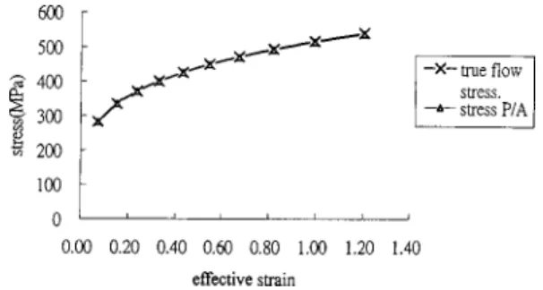
In order to validate the finite element simulation itself as an effective method for providing the necessary information for the compression loads and the geometric parameters of the barreled specimen, the simulation was first performed for the specimen that is 10 mm in height (2Ho/do⫽1.0) under frictionless condition, so
that the simulation results can be compared with theoretical pre-dictions. The free surface of the deforming cylinder, obtained from the finite element simulation, remains straight even under a large reduction in height to 4 mm. The flow stresses calculated according to the relation P/A at various effective strains共or axial compressive strains兲 during the compression are almost the same as those given by the stress-strain curve, as shown in Fig. 3, where P is the compression load, and A is the cross-sectional area of the specimen obtained from the finite element simulation. Although this good agreement between the simulation results and the theo-retical predictions only validates the finite element simulations under the frictionless condition, it also implies the feasibility of using this method to simulate the cylinder compression in the presence of friction. It is therefore meaningful to compare the true flow stress given in the finite element method as input data with the flow stresses calculated according to the present theoretical model, the E-H formula, and the mean flow stress method, using the compression loads and the geometric parameters of the de-forming specimen furnished by the finite element simulation results.
The compression load at various height reduction ratios (Ho
⫺H)/Hofor both the specimens under different frictional
condi-Fig. 2 Initial mesh for the finite element simulation„unit: mm…
Fig. 3 Comparison of the simulated flow stresses„PÕA…with the true flow stresses
Fig. 4 Compression load at various height reduction ratios
tions were obtained from the finite element simulations. The re-sults for the specimen of aspect ratio of 1.0 are plotted in Fig. 4. As seen in the figure, the compression load increases as the coef-ficient of friction increases.
In the E-H formula, the bulge profile is treated as a circular arc and the radius of the bulge curvature R is determined from an empirical formula共Horton et al. 关10兴兲 which has the form
R⫽共2H兲 2⫹共d
2⫺d1兲2
4共d2⫺d1兲
, (25)
where d1, d2are the minimum and maximum diameters of the
barreled specimen, respectively, and 2H is the instantaneous height of the specimen. The finite element simulation results were utilized to calculate the corresponding radius of the bulge curva-ture for the specimens under different frictional condition accord-ing to Eq.共25兲. Figure 5 shows the calculated radii of the bulge profile versus the mean effective strain of the cylinder with an aspect ratio of 1.0 under constant shear friction given by m ⫽0.1, 0.3, and 0.5, respectively. As seen in Fig. 5, the radius of the bulge profile decreases almost exponentially with the current height, and the specimen under higher friction coefficients has smaller radii of curvature as expected.
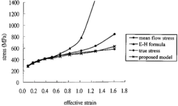
With the compression loads and the geometric parameters gen-erated from the finite element simulation results, the flow stresses calculated according to the proposed theoretical model, the E-H formula, and the mean flow stress method under various frictional conditions were evaluated. To limit the length of this paper, only the results of higher friction coefficients are discussed. The flow stress calculated from the three methods and the true flow stress are plotted against the mean effective strain in Figs. 6 and 7, respectively, for the specimen of aspect ratio 1.5 under the fric-tional conditions corresponding to m⫽0.3 and m⫽0.5. It is seen in Fig. 6 and Fig. 7 that the mean flow stress method shows good results over a range of low compressive strains in which the bar-reling is not significant. However, when the cylinder is deformed
to large effective strains, say ⑀¯⭓0.8, the calculated mean flow stress deviates from the true flow stress and the difference be-comes larger as the reduction increases, and the overestimated value of the flow stress at higher compressive strains becomes more significant as the coefficient of friction increases. It follows that the calculation based on the mean cross sectional area (A¯ ) is not sufficiently accurate, and the flow stress calculated from this method requires correction at higher reductions in height.
It is also seen in Fig. 6 and Fig. 7 that the flow stresses pre-dicted by the E-H formula agree reasonably well with the true flow stresses at lower compressive strains for both the frictional conditions of m⫽0.3 and m⫽0.5, but significant differences are noted at compressive strains higher than 0.4. As noted in both the figures, the calculated flow stress according to the E-H formula increases very rapidly when the compressive strain is greater than 1.0 for m⫽0.3, and greater than 0.8 for m⫽0.5. The difference between the predicted flow stresses and the true flow stresses may be attributed to the magnification of error in the approximate for-mula共Eq. 共25兲兲 for the radius of curvature R of the bulge curva-ture. The rapid increase in the calculated flow stress is due to the fact that R2 approaches the value of 2R as the strain increases,
which makes the term关1⫺R2/(2R)兴 appearing in Eq. 共2兲 tend to
zero. When R2⬎2R the flow stress is not obtainable from Eq. 共2兲.
This suggests that the E-H formula is applicable only to cylinders of relatively large aspect ratios.
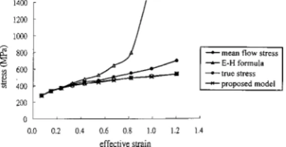
The flow stresses calculated according to the proposed theoret-ical model for m⫽0.3 are also plotted in Fig. 6. It is seen in this figure that the theoretical model underestimates the flow stresses over a range of axial compressive strains lower than 1.2, and overestimates the flow stresses at higher axial compressive strains. However, no marked difference is observed almost throughout the compression process. Although the difference would tend to in-crease with the increasing compressive strains, the variation is small and the flow stress still agrees reasonably well with the true flow stress. When the friction coefficient is increased to m⫽0.5, the flow stress calculated by the proposed theoretical model agrees very well with the true flow stress, even for large compres-sive strains, as indicated in Fig. 7, while the other two theories result in significant deviations from the true flow stress. Figure 7 also suggests that the proposed theoretical model would provide better results for specimens with significant barreling. On the whole, the proposed theoretical model is an improvement over the E-H formula and the mean flow stress method, both of which predict significantly higher flow stresses at higher compressive strains, and therefore increasingly deviate from the true flow stress of the material.
The comparison of the flow stresses calculated by the three methods with the true flow stress is also made in Fig. 8 for the specimen with an aspect ratio of 1.0 and a friction coefficient of 0.5. The lower the aspect ratio, the less is the radius of the barrel curvature, implying that an infinitely long cylinder would not bar-rel at all, as suggested by Johnson and Mellor 关11兴. Hence, de-creasing the aspect ratio from 1.5 to 1.0 significantly decreases the Fig. 5 Radius of bulge profile at various effective strains
„2HoÕdoÄ1.0…
Fig. 6 Comparison of flow stresses at various effective strains
„2HoÕdoÄ1.5;mÄ0.3…
Fig. 7 Comparison of flow stresses at various effective strains
barrel radius when subjected to the same height reduction ratio, thereby significantly increasing the inhomogeneity of deforma-tion. It is seen in Fig. 8 that the proposed theoretical model still predicts the flow stress consistently in close agreement with the true flow stress, and is superior to those given by the other two theories. This confirms the validity of the proposed theoretical model for calculating the flow stress for a barreled specimen un-der axial compression over the whole range of reductions in height.
6 Summary and Concluding Remarks
The purpose of this paper is to calculate the flow stresses for a barreled specimen, resulting from the presence of frictional force at the die-specimen interface during the compression test. The finite element simulations, instead of experimental results, were employed to generate the compression loads and the geometric parameters of the barreled specimen to validate the theoretical model developed in the present study. Unlike most of the pub-lished methods, which studied the incipient barreling only, the proposed theoretical model takes the continued barreling of the deforming specimen into account. As the present study shows, the analysis which is based on Hill’s general method for metal form-ing problems has yielded better results, both in magnitude and in trend, for the prediction of flow stresses in the barreled specimen in a compression test. It is also noted from the comparison made between the three methods that the proposed theoretical model can be used more effectively to the cylinder compression test with significant degrees of barreling.
In spite of extensive derivations and complex integrations re-quired in its application, Hill’s general method is certainly based on sound mathematical principles, and is flexible enough for
in-troducing various simplifying assumptions. The satisfactory esti-mate of the flow stress for the barreled specimen under inhomo-geneous compression indicates that the assumptions made in the proposed theoretical model are sufficiently realistic.
The velocity field adopted in the present study to calculate the mean effective strain for the barreled specimen also proves to be effective. The fact that the mean effective strain of the barreled specimen is approximately equal to the overall axial compressive strain to the first order simplifies the construction of the stress-strain relation in the compression test.
Furthermore, although the analysis correctly predicts the main trend for the flow stresses in a barreled specimen during the com-pression test, the proposed theoretical model would tend to under-estimate the flow stress of specimen at lower compressive strains. However, the difference between the calculated flow stresses and the true flow stresses is not significant. It is suggested that the inclusion of a shape factor in Eq.共18兲, which can allow for the change in the barrel geometry during the compression, might im-prove the accuracy of the proposed theoretical model.
Acknowledgment
The authors wish to thank the National Science Council of the Republic of China for their grant under the project NSC85-2216-E-002-027, which makes this research possible. They also would like to thank Professor J. Chakrabarty for his helpful discussions. References
关1兴 Siebel, E., 1923, Stahl und Eisen, Duesseldorf, 43, p. 1295.
关2兴 Avitzur, B., 1968, Metal Forming: Process and Analyses, McGraw-Hill, New York, pp. 102–111.
关3兴 Lee, C. H., and Altan, T., 1972, ‘‘Influence of Flow Stress and Friction Upon Metal Flow in Upset Forging of Rings and Cylinders,’’ ASME J. Eng. Ind., 94, Aug., pp. 775–782.
关4兴 Ettouney, O., and Hardt, D. E., 1983, ‘‘A Method for In-Process Failure Pre-diction in Cold Upset Forging,’’ ASME J. Eng. Ind., 105, pp. 161–167. 关5兴 Bridgman, P. W., 1952, Studies in Large Plastic Flow and Fracture,
McGraw-Hill, New York, pp. 9–86.
关6兴 Hill, R., 1963, ‘‘A General Method of Analysis for Metal-Working Pro-cesses,’’ J. Mech. Phys. Solids, 11, pp. 305–326.
关7兴 Lahoti, G. D., and Kobayashi, S., 1974, ‘‘On Hill’s General Method of Analy-sis for Metal-Working Processes,’’ Int. J. Mech. Sci., 16, pp. 521–540. 关8兴 Kobayashi, S., Oh, S. I., and Altan, T., 1989, Metal Forming and the
Finite-Element Method, Oxford University Press, Oxford, pp. 78–83. 关9兴 Chakrabarty, J., 1996, private communications.
关10兴 Horton, H. L., Ryffel, H. H., and Schubert, P. B., 1959, Machinist’s Hand-book, 16th Edition, The Industrial Press, New York, p. 152.
关11兴 Johnson, W., and Mellor, P. B., 1975, Engineering Plasticity, Van Nostrand Reinhold, London, pp. 110–114.
Fig. 8 Comparison of flow stresses at various effective strains