The Feasibility of Combating Multipath Interference
by Chirp Spread Spectrum Techniques
over Rayleigh and Rician Fading Channels
Ywh-Rm Tsai
Jin-Fu
Chang
Electrical Engineering Department
National Taiwan University
Taipei, Taiwan
10764
Electrical
Engineering
Department
National Central University
Chung-Li,
Taiwan 32054
Abstract- This paper s t u d i u the feasibility of usingchirp npread spectrum sign& to combat multipath in- U J P U t e r k r e n c e in binary dig4t.L communication syrtexru over Rayleigh a n d aidan fading chaual.. The chirp system
CM be implemented l u h g surkcs acoustic wave de-
vices a n d can be d ecompact in &e. Under also t he influence of additive white Gaudan noine,. the bit er- ror probability h u been rucecrrihlly derived. Through numerical examplea it in wltnsucd that chirp system can be used to greatly redwe the effect of multipath interference. The arrangement is q d t e attractive in deploying e.g. indoor wireless commnnicationa.
s s s
I. INTRODUCTION
Fw, 1 Bbcl: Ihq" dTr.omILw
Multipath interference results from reflection/refraction in the course of signal transmission. It has been a prob- lem of historical interest. It certainly has adverse effect on the quality of indoor and outdoor mobile communica- tions. Many techniques have been proposed to cope with multipath interference, e.g. diversity reception[l], channel equalization[2]-[4], and spread spectrum signaling[5]-[7].
vary in the opposite manner. In this paper we focus on the discussion of upchirp signals.
Mathematically a upchirp signal can be represented as follows [lo]
T h e
concept of chirp signals has been in existence for 18 ( t )
=
A8h[2Xfmt(1 -b - / h t ) ] , for 05
t<
Tb (1) several decades. Prior works related to chirp signals can 2be found in [8]-[18]. It has been extensively used in radar
systems for pulse compression[8]-[10]. In [11]-[14], possible where m=o Or '9
Ta
is
the bit and A the Bmpli-in data communications were &cussed,
A p
tude. In (l)S fo and f1 are starting frequencies plication such asconjunction with direct sequence spread spectrum signal for mark' The two
Whether it is feasible t o chirp signals to combat multi- path interference has been very rarely studied. In [12]-[13] it was only mention4 that chirp signals have the ability to cope with multipath interference, but so far there has been no quantitative analysiu done in the past.
mitter. The input signal is binary, i.e. m k ( 1 ) or space(0). A chirp signal is a sinusoid frequency is a linear funcm tion of time. The frequency of a chirp signal may vary in an increasing manner from a low frequency to a high fre- quency. We shall call such signal an upchirp. It can also
Jin-Fu Chang is SLO with Electried Engineering Department of Netional Taiwan U n i v m i t y , Tupd, Taiwan 10764.
~~~~i~ transformation was OfsPXe and m k , rwpectively. The channel used to send addressed in [15]-[16].
to combat the Doppler effect and jamming signal[l'l]-[18]. The concept Of chirp is to It can Chirp signals were also used in range8 'Om fo to f 0 ( l + M T b ) and fl to fl('+pl%)
be nonoverlapping.
be Using surface acoustic Wave
(SAW)
devicesand ~ r t i c d a r l y use-
ful in handheld telephone set* The P u r P e Of this study made ' O m F t
in
*"
whichis to mathematidy &y5' the feasibility Of chirp signals to reduce the effect of multipath interference in a
fdb channel. One p-sible application of our proposed system is IOW power indoor Wireless digital transmiMions. Sketched in Fig. 1 is the block disgram ofa &irp tranti binary digital COIXlInUniCatiOn System Over Rayleigh/Rician
11. CHANNEL MODEL
A . Rayleagh Fading Channel
the receiver can be represented as follows
bf
r(t) = C ~ j ~ ( t - t j ) + n ( t ) (2)
j = O
where M denotes the number of delay paths, s ( t ) the signal transmitted by the transmitter, and n(t) the channel noise.
"'
-
In (2), pj and t j are used t o denote the "signal strength" and the "propagation time from transmitter to receiver" of the j-th path.The path strengths
4,
for j=
O . . . M , are Rayleigh random variables, i.e.In a Rayleigh fading channel there is no direct or line-of- sight (LOS) path. All paths fade, but independently.
B . Rician Fading Channel
In a Rician fading channel, the zeroth path is in general a LOS path. The signal r(t) can be represented as follows
M
r ( t ) = As(t - t j )
+
x P j s ( t-
t j ) +n(t) (4)j = 1
which is a combination of a strong direct or LOS path and some reflected paths. The LOS path has a constant signal strength A, while the other reflected signal strengths p j , for j = 1.
. .
M, are Rayleigh random variables with distribution given in (3).Another important parameter to characterize Rician fad- ing channel is the ratio of the LOS power to the sum of all the reflected powers. Let us denote this parameter by
p, i.e.
When p
=
00, i.e. z,",,uj=
0, we have nothing but asingle path channel. In this case the received signal is only contaminated by the additive white Gaussian noise. When p = 0, i.e. A = 0, the LOS path vanishes and the channel becomes a Rayleigh fading channel of Sec. 1I.A.
C. Basic Assumptions
Al. The signal on each path is Rayleigh faded (except the zeroth path of the Rician channel). Different paths fade independently. As in [6]-[7], we assume that all paths have the same mean power level, i.e. U; = ua, for j = 1.. ,
M.
A2. Fading is slow with respect to Ts and frequency- nonselective with respect to the signal bandwidth. As a
result, the strength of the received signal docs not vary significantly within a bit duration.
A3. { t j
-
h}go
is assumed t o be uniformly distributed over one bit duration, i.e. (o,Tb)[6]-[?].A4.
@j}so
and {tj-
t.}go
are independent.A5. The channel noise in additive white Gaussian with A6. The receiver is always synchronized to the zeroth twc+sided power spectral density N0/2.
path.[l9]
111. ~ S U L T S
A . Rayleigh Fading Channel
For the convenience of our discussion, the block diagram of receiver can be simplified and drawn in Fig. 2. We examine the reception of a specific bit. We also assume
to
= 0, then tj in ( 2 ) hecomcs also the relative delay between the j-th path and the reroth path, since f+ - t o
=
t,. After mathematical derivation we obtain the following bit error probability P. when t l , *..
,
tbf are givenwhere
and W
=
fi&Tb=
f i t p p T b .Finally
P
-
IT' IT'
.
.
.
IT'
P.(t,, ' '.,
tM)dtl. .
d t n r (7)e
-
TfB . Rician Fading Channel
For Rician fading channel, there is now a LOS path. From (5), the relation between the
LOS
signal strength Aand the mean power of a delay path ua becomes 3) For each given finite value of W , we observe that P,
can only be lowered t o a limit no matter how high the signal-tenoise ratio is. This limit of course is due to the existence of multipath interference and the insufficiently large valueof W. This means that if the offered bandwidth is finite there exists a limit on P , which the system is never able to exceed.
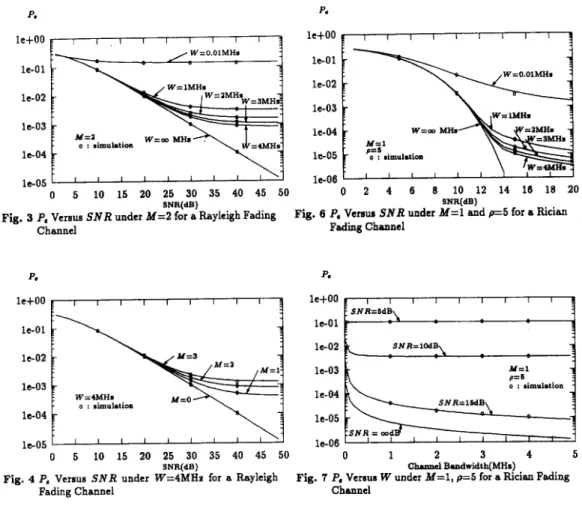
Fig. 4 presents another view by plotting P. versus S N R
under W
=
4MHs for various values ofM.
In this figureM
(8) After mathematical derivation we obtain the following
P.
when tl,. .
.
,
t M are givenU:
+
No-
2
A'2 ( 4 + U :
+
N0)c2p[2(~;:
+
U!+
N O ) P , ( t l , . . . , t M )=
where
Finally
Here we can notice that when U,, = U ) = 0, i.e. when there is no fading component, (6) reduces to the bit error rate of a pure additive white Gaussian noise channel, i.e.
1 %Aa
P
-
- e z p [ - - ]' - 2 2N0
Iv. NUMERICAL EXAMPLES AND DISCUSSIONS
In the following examples for the Rayleigh fading chan- nel the number of delay paths
M
is assumed to be 0, 1 , 2 or 3. We use SNR to denote the average signal-to-noise ratio, i.e. S N R=
E p a w s a ( 2 r f i t ) ] * Tb/No=
T b d / N o . SNR is taken to be 10, 20, 30, or 40 dB. The per channel band- widths W=
fifiTb considered are lM,ZM,
3M and 4MHI.
For Rician fading channel, the number of delay pathsM
is taken to be 1 which is the case considered in most studies. The influence from fading component depends mainly on the power ratio p of theLOS
t o the fading component, and is assumed t o be 1, 5 or 10. We define the SNR of Rician fading channel as the bit energy ofLOS
path to the channel noise, i.e. S N R=
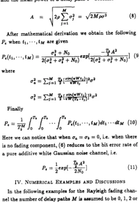
3 A a / N o .Fig. 3 plots P , versus S N R under different values of W for M = 2. In Fig. 3 we witness the followings
1) W
=
0.01M Hz=
10K Hs corresponds to the unspread case, i.e. f i = 0. We observe an unacceptably high value ofP.
no matter how big the value of S N R is. The unspread case is provided to demonstrate the improvement which can be offered by our chirp system.2) In the limitingcase when W + m we observe that the multipath interference can be almost completely removed which is reasonable. This curve al.0 gives us the lower bound of P. that our chirp system can achieve.
0 correapondi to the situation in which multipath chan- nel is nonexistent. The result of
M
=
0 is independent of the value of W and alsocoincides with the P . - S N R curve of the well known BFSK over a Rayleigh tading channel. The curveM
=
0 has L meaning quivalent to the curve of W=
m in Fig. 3. Both of them serve the purpose of telliig us the limit on the capability of our chirp system.In Fig, 5 we plot
Pe
versusW
forM
=
2 under various values of S N R . In thia case S N R=
00 corresponds t o anoiseless channel. The reason that Pa still shown a value of
P,
>
lo-' is due t o the existence of multipath interference and W being notlarge
enough. If W is pushed to m thenP, should approach zero eventually.
The remaining figures are done for Rician channel. In Fig. 6, we plot P . versus S N R under different values of W for p
=
5 in a Rician fading channel. Here we witness that1) In terms of P. when compare to Fig. 3, Rician fad- ing is less damaging than Rayleigh fading.
This
is very reasonable because in Rician channel there is a strong and constant strengthLOS
path.2) In the limitingcase when W + m, we observe that the multipath interference can be almost completely removed and is again reasonable. This curve also coincides with the
P.
-
S N R curve of the well known BFSK in an additivewhite Gaussian noise channel and gives us the lower bound of P . that our c h i p system can achieve in a Flician f d i g channel.
3) For each given value of W , we again observe that
P,
can only be lowered t o a l i t no matter how high the signal-to-noise ratio is. And this limit occurs at a S N Rlower than that in Rayleigh channel. Thin l i t of course is due to the existence of multipath interference and the insufficiently large value of W .
In Fig. 7 we plot P , vcrsus W for p
=
5 under various values of S N R . In this case S N R=
m Corresponds t oa noiseless channel. Trendr similar to those in
Fig.
5 of Rayleigh channel are observed.under W = 2MHz for various values of p. In this figure p = 00 corresponds to the situation in which fading component
is nonexistent and this curve also coincides with the Pe
-
S N R
curve of the well knownBFSK
in an additive white Gaussian noise channel.[7] M. Kavehrad, "Performance of nondiversity receivers for spread spectrum in indoor wireless communications," AT&T.Tech. Journal, vol. 64, pp. 1181-1210, July-August,
lgE5.
(81 C. E. Cook, "Pulse compression
-
key to more efficien- t radar transmission," Proc. IRE, vol. 48, pp. 310-316,March 1960. V. CONCLUSIONS
[e]
R. S. Berkowits, Modern Radar, Analysis, Evaluation, and We have in this paper propoaed and analyzed the perfor-system
N~~ york JohnwaeY
Qsons,
1965,fading channel. The validity of our analysis is not only verified by computer simulations but also supported by in- tuitive reasonings. Our key result obtained in this paper is the bit error probability P I .
Through extensive numerical examples we. indeed ob- serve that the effect of multipath interference can be great- ly reduced a t the cost of sufficient bandwidth. This should pose no problem in indoor environment in which the ra- diated power can be very well controlled in order to use as much bandwidth as one desires. When considering the limitation of technology, the bandwidth of chirp signals generated by SAW devices can exceed 100MHz[21], which should be wide enough for most applications. The sim- plicity and compactness of the system offers yet additional attractions. Error control coding techniques can be further employed to improve the performance when necessary.
Acknowledgement
The authors wish t o thank Mr. Tzu-Ymg Tong for stim- ulating discussions.
REFERENCES
[l] M. Kavehrad and P. J. McLane, "Performance of low- complexity channel coding and diversity for spread spec- trum in indoor, wireless communications," ATBT. Tech. Journal, vol. 64, pp. 1927-1965, October 1985.
[2] S. M. Sussman, "A matched filter communication system for multipath channels," IRE Trans. Inform. Theory, vol. IT-6, pp. 367-373, June, 1960.
[3] T. A. Sexton and K. Pahlavan, "Channel modeling and adaptive equalization of indoor radio channels," IEEE Se- lect. Areas. Commun., vol. SAC-8, pp. 114-121, Jan., 1989. [4] K. Pahlavan and J. W. Matthews, 'Performance of adap tive matched filter receivers over fading multipath channel-
s," IEEE Trans. Commun., vol. COM-38, pp. 2106-2113,
Dec., 1990.
[5] G. Turin, "Introduction to spread-spectrum antimultipath techniques and thar application to urban digital radio," Proc. IEEE, vol. 68, pp. 328-353, March, 1980. [SI G. Turin, "The dfects of mdtipath and fading on the per-
formance of direct-sequence CDMA systems,' IEEE Selec- t. Areas. Commun., vol. SACZ, pp. 597-603, July, 1984.
London: Artech House, 1988.
[I11 M. R. Winkley, 'Chirp signals for communications," IEEE WESCON Conv, 1962.
[I21 D. S. Dayton, "Coming to grip. with multipath ghosts," Electroniur, pp. 104108, November 27, 1967.
[I31 G. F. Gott, J. P. Newsome, and C. Eng, "H. F. data trane- mission using chirp signal.," Proc. IEE, vol. 118, pp. 1162- 1166, September, 1971.
[14] C. E. Cook, "Linear FM signal formats for beacon and communication systems," IEEE Trans. Aerosp. Electron. Syst., vol. AES-10, pp. 471-478, July, 1974.
[15] C. Campbell, Surface Acoustic Wave Devices and Their Signal Processing Applications, San Diego: Academic Press, 1989.
[16] M. A. Jack, P. M. Grant and J. H. Collins, "The theory, design, and applications of surface acoustic wave Fourier- transform processors,' Proc. IEEE, vol. 68, pp. 450-468,
April, 1980.
[17] J. Kim, T. Pratt and T. T. Ha, "Coded multiple chirp spread spectrum system and overlay service," IEEE GLOBECOM '88, pp. 17.6.1-17.6.5.
[18] A. K. Elhakcem and A. Targi, "Performance of hybrid chirp/DS sign& under Doppler and pnlsed jsmming," IEEE GLOBECOM '89, pp. 45.5.1-45.6.8.
[le] B. solaiman, A. Glavieux and A. Hillion, 'Error probabil- ity of fast frequency hopping spread spectrum with BFSK modulation in selective Rayleigh and lelective Riaan fad- ing channels," IEEE Trana. Commun., vol. COM-38, pp.
233-240, Feb., 1990.
[ZO] A. Papoulis, Probability, Random Variables and Stochastic Processes, New York McGraw-Hill, 1984.
[21] J. Burnaweig and J. Wooldridge, 'Ranging and data trans- mission using digital encoded FM-chirp surface acoustic wave filters," IEEE Trans. Sonic. Ultrason., vul. SIJ-20,
P. le+OOk I I I I I I I I I
1
W=O.OlMlh le-01 o : mimobtion W=m MH. le-04 0 5 10 15 20 25 30 35 40 45 50 P. le+00! I 1 I I I I I I I1
W=O.OlMH. l e 0 2i
I
W=lMHs W=m MH. le-03 le-04 1 .-OB--
--
0 2 4 6 8 10 12 14 16 18 20 SNR(dB) SNR(dB)Fin. 3
P.
Versus S N R under M = 2 for a Flayleigh Fading Fig. 6P.
Vemus S N R under M = l and p=5 for a Rician Channel P. le+00E I I I I I I I I I3
le-01 le-02 le-03 le-04 l e 0 5 0 5 10 15 20 25 30 35 40 45 50 SNR(dB)Fig. 4 P. Versus S N R under W=4MHs for a Rayleigh Fading Channel
P.
0 1 2 3 4 5
Ch.nn.1 B.ildmdth(MHs
Fig. 5
P.
Versus W under M = 2 for a FlayLigh Fading Channel Fadiing Channel P. le-02 SNR=lCdB le-03 le-04 le-05 le-06 o : simulation 0 1 2 3 4 5 Ch.mrcl B d w i d t h ( M H s )Fig. 7 P. Versus W under M = l , p=5 for a Rician Fading Channel P, le-01 le-02
-
le-03 le-04 le-05 le-06 le-07-
0 2 4 6 8 10 12 14 16 18 20 S N R ( WFig. 8