Contributed Paper
Manuscript received January 12, 2005 0098 3063/05/$20.00 © 2005 IEEE
CORDIC-Based Architecture with Channel State Information for
OFDM Baseband Receiver
Chia-Sheng Peng, Student Member, IEEE, Yuan-Shin Chuang,
and Kuei-Ann Wen, Senior Member, IEEE
Abstract — An efficient architecture for OFDM baseband receiver based on coordinate rotation digital computer (CORDIC) algorithm is proposed with channel state information (CSI). Two dual-mode CORDIC modules are designed for synchronization and equalization. A modified demapping method using CSI helps to provide sub-channel status, and therefore decreases packet error rates especially for some sub-channels with extremely low SNR. A combined algorithm suitable for CORDIC is proposed for not only estimate and compensation of channels but synchronization for carrier frequency offset and sampling clock offset. Allocation, timing analysis and complexity for all functional blocks in the receiver are proposed, including front-end processing, FFT, inner receiver, and outer receiver. Complete tests for packet error rate are simulated under an integrated platform considering of RF front-end non-ideal parameters, filters, quantization, and channel models. Simulation results of practical circuits on AWGN and channel models are presented and prove the improvement of the receiver. The design
occupies about 424k equivalent gate count and 7.3 mm2 core
size in 0.18-µm CMOS.
Index Terms — OFDM, Wireless LAN, CORDIC, channel state information
I. INTRODUCTION
Orthogonal Frequency Division Multiplexing (OFDM) technique has many advantages to overcome multipath effects and narrowband interference by using guard intervals and splitting sub-carriers; moreover, easily working together with interleaving and coding techniques, OFDM-based systems substantially improve performance under fading channels [1]. Therefore, more and more wireless systems adopt coded OFDM as transmission techniques, for example, WLAN IEEE 802.11a/g and ETSI DVB-T [2]-[3]. However, OFDM-based systems are sensitive to channels, carrier frequency offset (CFO) and sampling clock offset (SCO); other effects caused from RF front-end non-ideal properties, such as phase noise,
PA non-linearity, I/Q mismatch, etc, also degrade quality of transmission [4]. Among these effects, phase errors caused by CFO, SCO and phase noise (PN) result in phase rotation for all
sub-carriers and seriously destroy quadrature property of QAM signals, especially for higher-order QAM signals. Multipath channels, on the other hand, generate channel response including amplitude and phase. Therefore it is necessary to estimate and compensate these effects by synchronization and equalization [5]. But under frequency-selective fading environment, some sub-carriers are probably in deep fading and result in extremely low SNR. Most part of the error bits results from these sub-carriers and obviously increase packet error rate (PER) in packet-based transmission. Using channel state information (CSI) to decrease PER under such environment has been proposed for WLAN [6]-[7].
CORDIC algorithm realizes conversions between rectangular and polar coordinates, and many other useful applications [8]. Some methods use CORDIC for frequency offset compensation and FFT calculation [9]. In this paper two dual-mode CORDIC modules are designed before and after FFT: the former serves for calculation and correction for CFO, and the latter for the algorithm unifying channel estimation, phase tracking and equalization. For performance improvement under multipath fading channels, a new demapping rule is proposed that reduces hardware complexity of the equalizer and employs CSI to achieve 3 to 6 dB improvement for different data rates. Unlike some methods adopting sub-channel power as CSI calculation in the decoder [7], the method employs sub-channel amplitude in the modified demapping to eliminate the use of complex-valued divisions from the equalizer. Under some special cases of severer channel responses 18 dB improvement (from 50 dB to 32 dB CNR required) for 64QAM with 3/4 coding rate can be achieved. Besides, for full packet transmissions the paper also proposes the designs of frame detection, automatic gain control (AGC), and symbol timing detection.
A software simulation platform is also introduced that integrates baseband, RF, analog components, and channel models. On the platform, non-ideal parameters, channels and noise can be co-simulated with the proposed baseband transceiver. Simulation results for PER of practical circuits on AWGN and channel models are also proposed to verify the improvement of using CSI method. Allocation, timing analysis and complexity for all functional blocks in the receiver are presented, including front-end processing, FFT, inner receiver, and outer receiver. The RAM-free design makes the baseband processor more convenient as part of system-on-a-chip and the total area occupies about 424k equivalent gate count and 7.3 mm2 core size in 0.18-µm CMOS.
This work was sponsored jointly by the Ministry of Education and the National Science Council, Taiwan under the contract number NSC-93-2220-E-009-011.
The authors are with the Department of Electronics Engineering, National Chiao Tung University, Hsinchu, 300, Taiwan
(E-mail: cspeng.ee87g@nctu.edu.tw, piden.ee86@nctu.edu.tw, stellawen@mail.nctu.edu.tw)
II. DESIGN OF OFDM RECEIVER
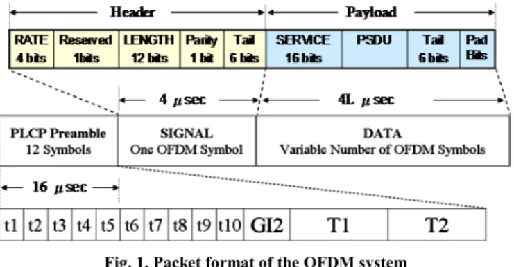
The system uses a packet-based method that a packet is transmitted with preamble, header and payload data as shown in Fig. 1. The preamble signals, including 10 short and 2 long preambles, are used for frame detection, gain control, CFO compensation, symbol timing detection, and channel estimation. The header signal stores payload length and data rate, which indicates the modulation type and the coding rate. All payload data are partitioned into OFDM symbols and totally L in number. Each OFDM symbol occupies 4µ second and contains 4 pilots and 48 data symbols. Data symbols can be modulated with BPSK, QPSK, 16QAM or 64QAM, and coded with puncture-rate: 1/2, 2/3 and 3/4. The allocated bandwidth and the sampling clock rate is 20 MHz, and the data rates vary from 6-54 Mbits/sec.
A. Functional blocks for OFDM receiver
Fig. 2 indicates the functional blocks and signals of the proposed OFDM receiver according to the packet format above. The design includes an inner receiver and an outer receiver: the former is defined for signal processing such as synchronization and equalization, whereas the latter for logic processing such as deinterleaving and decoding [10]. Symbols transmitted recover from infection of non-ideal parameters and channel response, and the demapping as bridge from inner receiver to outer receiver translates these symbols into a bit-level sequence. The outer receiver detects and corrects errors bits from the sequence.
B. Front-end processing
Front-end processing includes functions in front of inner receiver: SRRCF, frame detection, AGC, and STD. The complex-valued input signal after SRRCF is down-sampled and operates at 20 MHz with 10-b resolution. Because the short preamble repeats every 16 samples, the frame detection uses a sliding decision statistic that is calculated as
2 1 2 2 1 * 16
⋅
=
∑
∑
= − + = − − + − + N i i N n N i i N n i N n nr
r
r
M
(1)where N is the length of the correlator [11]. The sliding Mn retains statistical that varies with SNR as shown in Fig. 3a. Therefore the threshold of the design is decided according to lower SNR value down to 3 dB. The denominator of (1) is viewed as the power of input signal and can be translated into
decibel Pn,dB by a look-up table (LUT) that compares with the peak power ratio of ADCs. The VGA gain to adjust is obtained by dB t dB n dB pre dB next
G
P
PAPR
G
,=
,+
,−
, (2)where PAPRt,dB is the target PAPR of input signal, and Gnext,dB and Gpre,dB are the next and the previous gain, respectively. The adjustment of AGC is done twice so that Pn,dB is adjusted toward the target PAPR. As shown in Fig. 3b there are many different initial input gains that vary from about 40 to 55 dB, i.e., the input signal to ADCs is too small and then it will be adjusted to the target value 9 dB.
Because of real-valued property in frequency domain, the long preambles are symmetric-conjugate and therefore STD can take half the long preamble, 32 taps in number, to implement a matched-filter that is designed with 2-b coefficients. As Fig. 3c shows, there are two peaks at the end of two long preambles. The proposed STD traces the second
Fig. 1. Packet format of the OFDM system
ADC Frame Detection and AGC Symbol Timing Detection (STD) CORDIC-Assistant
CFO Acq. And Compensation Symbol Timing Controller (STC) Pilot-Based Phase Tracking Radix-8 FFT Filtered Channel Estimate De-mapping De-interleave Viterbi Decoder De-scrambler Header Check SRRCF
Data and Pilots Extractor CORDIC-Based
Equalizer Gain
to VGA Frame detect RSSI k φˆ l k , ˆ θ k Aˆ l k Y , n l z, l k Pˆ, l k Dˆ, n
z
nr
Output bits Header Info. I/Q data rate trigger timing l k Yˆ, Inner Receiver Outer Receiver ADC Frame Detection and AGC Symbol Timing Detection (STD) CORDIC-AssistantCFO Acq. And Compensation Symbol Timing Controller (STC) Pilot-Based Phase Tracking Radix-8 FFT Filtered Channel Estimate De-mapping De-interleave Viterbi Decoder De-scrambler Header Check SRRCF
Data and Pilots Extractor CORDIC-Based
Equalizer Gain
to VGA Frame detect RSSI k φˆ l k , ˆ θ k Aˆ l k Y , n l z, l k Pˆ, l k Dˆ, n
z
nr
Output bits Header Info. I/Q data rate trigger timing l k Yˆ, Inner Receiver Outer ReceiverFig. 2. Functional blocks of the proposed OFDM receiver
Fig. 3. (a) Decision statistic Mn in frame detection under different
SNR (b) Adjusted power of input signal toward the target PAPR (c) Matched-filter output from STD
Contributed Paper
Manuscript received January 12, 2005 0098 3063/05/$20.00 © 2005 IEEE peak and acquires the symbol timing, which will be sent to
STC shown in Fig. 2. Based on the symbol timing detected from STD, STC selects samples and also overcome timing drift caused by SCO because even a tiny SCO exists in a clock source that drives ADCs or DACs, through a long period, the symbol timing will lead or lag. STC in the design can compensate the timing slide according to the estimated SCO in the phase tracking.
C. CORDIC-based architecture for the inner receiver
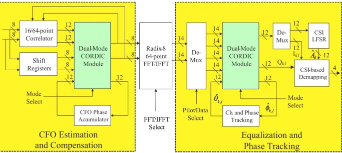
The inner receiver architecture is illustrated in Fig. 4 where there are two main functional blocks both based on dual-mode CORDIC modules. In front of FFT, CFO will be estimated and compensated. The 64-point FFT transforms signals from time-domain into frequency-time-domain. After FFT, channel response will be estimated, filtered, and equalized; simultaneously, phase error will be tracked and compensated. A novel algorithm unifies equalization with phase tracking in polar-coordinate so that a dual-mode CORDIC module can deal with all the operations in the algorithm by precise allocation.
1) Design of dual-mode CORDIC module
The proposed dual-mode CORDIC is an iterative algorithm used to rotate a 2x1 vector with a certain angle (phase-rotation mode), or to acquire amplitude and angle from a 2x1 vector (rectangular-to-polar mode). General methods to realize these functions need LUTs, complex-valued multipliers, and dividers. CORDIC reduces complexity in hardware by use of simple components like adders, comparators and shifters. Besides, implementation of a CORDIC module is easily designed by pipeline because of the similar operations in the iteration. The accuracy of the CORDIC module increases with larger iterative number N and ith iterative formula is defined as
1 1
1
2
2
1
i i i i i i i ix
x
y
y
µ
µ
− + − +−
=
(3) 1tan (2 )
i iθ
=
− −where i=0,1,..., N-1, [xi yi]T is the input vector, [xi+1 yi+1]T the vector rotated, θi the practical rotative angle in this iteration, and µi decides the direction of the rotation. The vector [xi yi]T rotates clockwise if µi =1 whereas anticlockwise if µi = -1, as µi is given by 1 0 ( ) ( ) (rectangular-to-polar mode) ( ) (phase-rotation mode) i i i i r r r sign x sign y sign µ − µ θ ψ = − ⋅ = − −
∑
(4) where ψ is the reference angle to rotate. As the process converges at the last iteration, the vector [xi yi]T is multipliedby the factor 1 2 0 1 N 1 2 i N i k − − =
=
∏
+ to maintain the sameamplitude of the input vector.
In phase-rotation mode the direction of the rotation is decided by comparison of the accumulated angle and its reference in each rotation. The vector rotates clockwise if the former is larger than the latter or else it rotates anticlockwise. In rectangular-to-polar mode the vector rotates to positive
x-Iterative Unit i x i y -1 tan (2 )−i mode 1 i x+ 1 i y+ ψ (b) Sign Sign 1 -1 -1 tan (2 )−i mode ADD / SUB ADD / SUB -i 2 M u x C m p ADD / SUB i x i y 1 i x+ 1 i y+ ψ (a) i µ Iterative Unit 0 x 0 y mode ψ 0 Iterative Unit B U F F E R … Iterative Unit B U F F E R -1 1 tan (2 )− -1 (1 ) tan (2− −N ) N x N y … … -1 0 tan (2 )− (c) B U F F E R N k N k ou t x ou t y Sign M u x i ϕ ϕi+1 i ϕ 1 + i ϕ N ϕ Iterative Unit i x i y -1 tan (2 )−i mode 1 i x+ 1 i y+ ψ (b) Sign Sign 1 -1 -1 tan (2 )−i mode ADD / SUB ADD / SUB ADD / SUB ADD / SUB -i 2 M u x C m p ADD / SUB ADD / SUB i x i y 1 i x+ 1 i y+ ψ (a) i µ Iterative Unit 0 x 0 y mode ψ 0 Iterative Unit B U F F E R … Iterative Unit B U F F E R -1 1 tan (2 )− -1 (1 ) tan (2− −N ) N x N y … … -1 0 tan (2 )− (c) B U F F E R N k N k ou t x ou t y Sign M u x i ϕ ϕi+1 i ϕ 1 + i ϕ N ϕ
Fig. 5. (a) Structure of an iterative unit (b) Symbol of a single unit (c) Architecture of the pipeline dual-mode CORDIC module
CFO Phase Accumulator 12 12 8 8 12 12 16/64-point Correlator Shift Registers Dual-Mode CORDIC Module Ch. and Phase Tracking 12 12 14 14 14 14 12 12 8 8 64-pointRadix-8 FFT/IFFT FFT/IFFT Select 14 14 CSI-based Demapping De-Mux CSI LFSR Pilot/Data Select
CFO Estimation
and Compensation
Equalization and
Phase Tracking
8 8 ModeSelect SelectMode
12 12 12 Ik,l Qk,l l k, ˆ θ k Aˆ 4 l k, ˆ φ Dual-Mode CORDIC Module De-Mux. CFO Phase Accumulator 12 12 8 8 12 12 16/64-point Correlator Shift Registers Dual-Mode CORDIC Module Ch. and Phase Tracking 12 12 14 14 14 14 12 12 8 8 64-pointRadix-8 FFT/IFFT FFT/IFFT Select 14 14 CSI-based Demapping De-Mux CSI LFSR Pilot/Data Select
CFO Estimation
and Compensation
Equalization and
Phase Tracking
8 8 ModeSelect SelectMode
12 12 12 Ik,l Qk,l l k, ˆ θˆk,l θ k Aˆk Aˆ 4 l k, ˆ φˆk,l φ Dual-Mode CORDIC Module De-Mux.
axis. The desired angle of the input vector is the last accumulative angle
∑
− = − = 1 0 i i κ κ κ θ µξ and the amplitude is the
length on x-axis after all iterative rotations are finished. The architecture of the proposed dual-mode CORDIC is shown in Fig.5. The equations in (3) and (4) are implemented as shown in Fig .5a. The multiplication 2-i adopts shifters for xi and yi. According to the control signal “mode”, µi selects addition or subtraction in “ADD/SUB” blocks. Fig. 5b shows the symbol of a single iterative unit. In Fig. 5c the output port
xout and ξN are amplitude and angle of the input vector in rectangular-to-polar mode whereas xout and yout represent the output vector being rotated in phase-rotation mode. The buffer located between every two iterative units can shorten critical path and therefore raise clock rate. The signal ψ and “mode” are propagated through buffers and then all units are able to operate at different modes with different angles. However, increasing the number of buffers increases hardware complexity. Based on requirement of accuracy and clock rate in practical design, the module adopts nine iterative units and inserts three buffers totally.
2) CFO estimation and compensation
Coarse CFO is estimated when AGC has been operated. The angle calculated from the same correlator in frame detection calculates CFO value in maximum likelihood method:
)
(
1 * 16∑
= − − +⋅
− +∠
=
N i n N i n N i cr
r
Φ
(5)The value in (5) means the phase rotation caused by CFO within 16 samples and then the coarse CFO value can be calculated by the sampling period Ts:
Hz
)
16
2
/(
s c cΦ
T
f
=
⋅
∆
π
(6)Because the angle in (5) only varies between π and -π, the coarse CFO estimate has the largest range up to ±625 KHz. Because the phase compensation is operated at Ts, the true CFO value in (6) is not necessary: only the angle caused by CFO within a sample is required. Before fine CFO is estimated, the signal must be rotated according to the accumulated angle so that the residual CFO is within ±156.25 KHz, which is the largest estimate range of fine CFO:
)
16
/
exp(
c n nr
jnΦ
c
=
⋅
−
(7)where the sampling period is neglected and the division 16 is easy to be implemented. After STD decides the symbol timing, the estimate of fine CFO can take the correlation value of the two identical long preambles:
)
(
64 1 * 64 128∑
= − +⋅
− +∠
=
Φ
i i l i l fc
c
(8)where l is the last index of long preambles. The final CFO-compensated signal is represented as
(
/
16
/
64
)
]
[
exp
j
Φ
Φ
n
r
z
n=
n⋅
−
c+
f (9)which includes the coarse and the fine CFO estimate. Equations of (5) and (8) calculate angles from complex-valued signals, whereas (7) and (9) rotate complex-valued signals by
some angles. Therefore a dual-mode CORDIC module can serve for these operations. Both the coarse and the fine CFO estimate are acquired by the CORDIC module and stored to CFO phase accumulator shown in Fig. 4, and then Φc and Φf in (9) will be sent into the CORDIC module to rotate the signal sequence {rn} in the shift registers.
3) Filtered channel estimation
After the pre-FFT signal is compensated by CFO and the guard interval is removed, the post-FFT signal of the lth OFDM symbol is given by
k
N
n
j
z
Y
N n n l k lexp(
2
(
/
)
1 0 , ,=
∑
⋅
−
π
− = (10) where N is the number of FFT points. The wideband signal istransmitted over frequency-selective fading channel. Because the duration of a packet is relatively shorter than the coherence time of indoor channel, i.e. velocity less than 10 km/hr, the channel is assumed to be constant during a packet period. Then the channel transfer function at kth subcarrier frequency can be represented as time-invariant model:
∑
−
=
i u i i kh
j
k
T
H
exp(
2
π
(
τ
/
)
(11)where hi is the complex-valued tap, τi is its path delay, and Tu the duration of FFT. Under consideration of residual CFO ∆f, SCO value ζ = ( Ts’-T
s ) / Ts, and symbol timing offset nε , the post-FFT signal can be simplified as an equivalent model [10]:
l,k u g u k ε k l,k ε l,k W )/T T (T πl j π(k/N)n j H )a α(n Y + + = ] 2 [ exp ] 2 [ exp φ (12)
where α(nε) is attenuation function of nε, al,k the transmit data,
Tg the guard interval, Ts the sampling time, Ts’ the offset sampling time, Wl,k the noise caused from AWGN, nε , ICI, phase noise and other non-ideal parameters, and
k
fT
uk
≈
∆
+
ς
⋅
φ
. The channel transfer function combinedwith the effect caused from symbol timing error nε together with attenuation function can be represented as
]
)
/
(
2
exp[
)
(
~
ε επ
α
n
H
j
k
N
n
H
k=
k (13)Therefore (12) can be re-written as
l,k k l,k l,k
W
k
πl
j
H
a
Y
+
+
⋅
=
]
)
(
5
.
2
[
exp
~
α
ζ
(14)where α=∆fTu is phase shift caused from the residual CFO in an OFDM symbol, (Tu+Tg )/Tu)=1.25, and k = -26,…-1,1,...26 in the system. Considering that (ζ•k+α) is small enough in (14) and the pre-known signal is defined as ãl,k in the preamble with
l=λ,λ+1, the estimate of kth sub-channel is generally given by
2
/
)
~
/
~
/
(
ˆ
, 1 , 1 , ,k k k k kY
a
Y
a
H
=
λ λ+
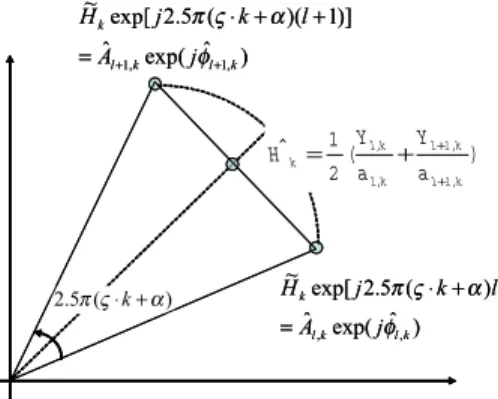
λ+ λ+ (15)And then the signal is equalized as k k l k l
Y
H
a
ˆ
,=
,/
ˆ
(16)As shown in Fig. 6 the amplitude of Ĥk is shorter than the practical value; moreover adjusting the phase shift in (14) can improve the estimates of channel response and phase tracking. Therefore the design uses a CORDIC module to translate the
Contributed Paper
Manuscript received January 12, 2005 0098 3063/05/$20.00 © 2005 IEEE c
omplex-valued signal from (14), which is divided by the known transmit signal ãl,k into polar-coordinate:
1 , ), ˆ exp( ˆ ~ / ] ) ( 5 . 2 exp[ ~ ~ / , , , , , , + = = + + ⋅ =
λ
λ
φ
α
ς
π
l j A a W l k j H a Y k l k l k l k l k k l k l (17)Then the amplitude and the phase of kth sub-channel are estimated by the two long preambles:
2 / ) ˆ ˆ ( ˆ 2 / ) ˆ ˆ ( ˆ , 1 , , 1 , k k k k k k A A A + + + = + = λ λ λ λ φ φ φ (18) Note that the phase in (18) is not an actual phase of
sub-channel but being a reference for phase compensation. Based on the correlative property between adjacent sub-channels, the estimate of sub-channel can be improved further by delivering them into a filter with 3 taps [0.25, 0.5, 0.25], which reduces noise about 3 dB. Simulation reveals that the total system performance on PER will improve about than 1 dB using the filter for 64QAM with 3/4 coding rate.
4) Phase tracking
The angle shown in Fig. 6 helps to estimate SCO and residual CFO, given by
k w k w k k k N N k , 1, , , , , 1 ) ( 5 . 2 ˆ ˆ λ λ λ λ α ς π φ φ δ − + + ⋅ = − = + + (19)
where Nw,l,k means phase noise caused by Wl,k /ãl,k in (17). Because k is symmetric, the first estimate of residual CFO can be obtained by 0 , 26 ... 26 , 52 5 . 2 1 ˆ 1 =− ≠ ⋅ =
∑
+ k k k k δ π αλ (20)and the first estimate of SCO is given by
π δ δ π δ δ ςλ 1755 2 5 . 2 ˆ 1 26 26 1 26 1 1 26 26 1 1
∑
∑
∑
∑
∑
= =−− = − − = = + − = ⋅ ⋅ − = k k k k k k k k k k (21)The phase which shall be compensated for (λ+m)th OFDM symbol and kth sub-channel is defined as
,...
4
,
3
,
2
)
5
.
0
)(
ˆ
ˆ
(
5
.
2
ˆ
ˆ
1 1 ,=
−
+
⋅
+
=
+ − + − +m
m
k
m m k k m λ λ λφ
π
ζ
α
θ
(22)Therefore the post-FFT signal is compensated with the phase from (22) and shown as
,... 3 , 2 , ) ˆ exp( ˆ , , , =Y −jθ +k⋅ρ l=λ+ λ+ Ylk lk lk STC (23)
where ρSTC=0 or ±π/64 is the compensative phase from STC,
depending on the criterion of SCO. Symbol timing error accumulates when SCO exists, and therefore, the design proposes the criterion to decide whether the STC should be triggered or not:
64
ˆ
)
5
.
0
(
5
.
2
π
m
−
ζ
λ+m≥
π/
(24)Once the criterion in (24) happens, the STC moves the symbol timing forward or backward according to the sign of ζˆλ+m and the compensative phase ρSTC is selected correspondingly.
The output signal from (23) extracts 4 pilots and 48 data signals, all adjusted with phase tracking: Pˆl,kandDˆl,k. The
pilots occupies at k= -21,-7,7,21 in each OFDM symbol. The phase recovers from the known pilots:
− = + ∠ = ∠ = 1 , ˆ 1 , ˆ ˆ , , , , , , k l k l k l k l k l p P P P P π φ (25)
The adaptive tracking of residual CFO is then obtained by
m m m k k m p m
m
+ − + + − − = + +Θ
+
=
−
⋅
⋅
=
Θ
∑
λ λ λ λ λµ
α
α
π
φ
0 1 21 , 7 , 7 , 21 , ,ˆ
ˆ
)]
5
.
0
(
5
.
2
4
[
ˆ
(26) and that of SCO is obtained bym m m k k m p k k m p m m + − + + − − = + = + + Λ + = − ⋅ − = Λ
∑
∑
λ λ λ λ λ λ µ ζ ζ π φ φ 1 1 7 , 21 , , 7 , 21 , , ˆ ˆ ) 5 . 0 ( 5 . 2 56 ˆ ˆ (27)where µ0 and µ1 are step sizes that adaptively control the speed of convergence. The estimate of SCO is also used for the criterion in (24) for symbol timing adjustment. The amplitude and the phase of (17) and (25) are acquired by the dual-mode CORDIC module after FFT as shown in Fig. 4, whereas the phase rotation in (23) uses another mode of the same module. The data signal in (23) is only compensated with phase error caused by channel response, residual CFO, and SCO, but not normalized by amplitude of channel response, which will be considered in the demapping.
5) Modified demapping using CSI
As a bridge between the inner and the outer receivers, demapping translates complex-valued symbols into a bit-level sequence according to mapping rules and modulation types in the transmitter. In general, before demapping, the data signal extracted from (23) is normalized by channel amplitude estimated in (18) and given by
k k l k l
D
A
D
'ˆ
,/
ˆ
,=
(28)Thus the signal in (28) can be regarded as the signal in the transmitter coupled with noise, as shown in Fig. 7. The noise mainly results from thermal noise and channel attenuation, which also inflict inaccuracy on synchronization, channel estimation and equalization, and causes more noise further. Also, the noise is enhanced by the division in (28) because of denominators with smaller channel amplitudes. A bit-level
) ˆ exp( ˆ ] ) ( 5 . 2 exp[ ~ , ,k lk l k j A l k j H φ α ς π = + ⋅ ) ˆ exp( ˆ )] 1 )( ( 5 . 2 exp[ ~ , 1 , 1k l k l k j A l k j H + + = + + ⋅ φ α ς π ) ( 2 1 ˆ , 1 , 1 , , k l k l k l k l k a Y a Y H + + + = ) ( 5 . 2 πς⋅k+α ) ˆ exp( ˆ ] ) ( 5 . 2 exp[ ~ , ,k lk l k j A l k j H φ α ς π = + ⋅ ) ˆ exp( ˆ )] 1 )( ( 5 . 2 exp[ ~ , 1 , 1k l k l k j A l k j H + + = + + ⋅ φ α ς π ) ( 2 1 ˆ , 1 , 1 , , k l k l k l k l k a Y a Y H + + + = ) ( 5 . 2 πς⋅k+α
sequence after demapping is denoted as {dl,k,ν}, in which
ν=0,…,M-1, and M is the number of bits per symbol
corresponding to different modulation, e.g., M=1,2,4,6 for BPSK, QPSK, 16QAM and 64QAM, respectively. Since the complex-valued signal in (28) is composed of real and image parts, the demapping function of 64QAM, for example, extract 3 bit-level signals from each part, as shown in Fig. 8. The slopes in Fig. 8 depend on the minimum distance between any two constellations and the space ∆ is half the minimum distance. Based on requirements of soft-decision and hardware complexity, the output sequence from demapping is assigned to 4-b resolution. Besides, the resolution is restricted for saving more buffers in the deinterleaving and the decoder.
Due to frequency-selective fading channels, sub-channel power varies randomly. Some sub-channels attenuate severely and result in extremely low SNR, and then most part of error bits happens on these sub-channels. The modified demapping using CSI adopts sub-channel amplitude to weight the bit-level sequence; and therefore, the reliability of those bits acquired from these severer sub-channels can be lowered, and the performance of the decoder based on maximum likelihood will be improved. Weighting the path metric by sub-channel power from CSI has been highlighted in [7], but using amplitude as weighting factor is a better way because the division in (28) can be eliminated and the performance can be maintained. The
demapping rules considering CSI for 64QAM in 802.11a, for example, are proposed, without any division:
< < − < < − − < < − + − − < < − + < < − < < = < < − − < < − + > − < = − < − > = = λ λ λ λ λ λ λ λ λ λ λ λ λ λ λ λ λ λ τ λ λ λ λ λ λ λ λ λ λ τ λ λ λ λ τ 7 5 , 6 3 , 2 3 ), 2 ( 5 7 , 6 or 7 , 5 3 , 5 3 , 4 3 5 , 4 5 G , 3 G , , , , ˆ , , , , , , , , , , , 2 , , , , , , , r , r 1 , , , , , 0 , , mod k l r k l r k l r k l r k l r k l r k l r k l r k l r k l r k l r k l k l r k l r k l r k l r k l k l k l k l r k l r k l r k l k d G d G d G d G d G d G d G d G d G d G d G d G d G d G d G d d otherwise d G d G d G A K λ (29) where Kmod is a normalized factor of modulation, and Gr the
coefficient for different coding rates.
D. Design of FFT/IFFT and outer receiver
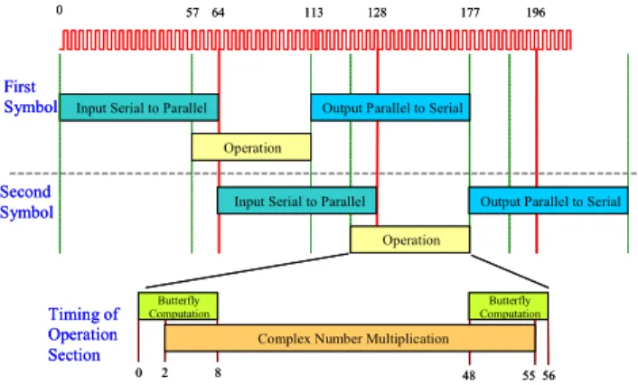
As shown in Fig. 2, FFT and outer receiver are regarded as independent modules in the receiver. Because of half-duplex operation in the system, an identical dual-mode module FFT/IFFT can be designed for both transmitter and receiver. Under analysis for radix-8 design, it needs 16 operations of radix-8 butterfly and 49 operations of complex-valued multiplication to implement a 64-point FFT/IFFT. Therefore the design employs a radix-8 butterfly and a complex-valued multiplier to acquire latency with only 113 clock cycles, by meticulous arrangement for timing as shown in Fig. 9. Although outer receiver includes many functions, it is viewed as an integrated module fully processing bit-level sequence from demapping. The deinterleaving is the inverse operation of block interleaving, and the de-puncture fills up those punctured bits with neutral values. The decoder is implemented by Viterbi algorithm, which searches for the maximum path metric through
∑∑ ∑
=−01 =−01 =−01 ,, ' , , L l K k M nrz k l k l c d ν υ ν (30) where { nrz,, } k lc ν denotes the nonreturn-to-zero codeword associated with a particular path through the trellis, and d’
l,k,ν is 5 10 0 15 b0 5 10 0 15 b1 128 256 384 512 640 768 896 0 1023 5 10 0 15 Index b2 3 , , 0 , ,k , lk l d d 4 , , 1 , ,k , lk l d d 5 , , 2 , ,k , lk l d d ∆ input, 10 bits out pu t, 4 bit s
Fig. 8. Demapping functions of 64QAM
Fig. 7. Constellations from different mapping rules under different C/N conditions
57 64
Input Serial to Parallel
113 177
First Symbol
Second Symbol
Output Parallel to Serial
Operation Operation
Butterfly
Computation ComputationButterfly
128
0 2 8 48 5556
Complex Number Multiplication
0 196
Timing of Operation Section
Input Serial to Parallel Output Parallel to Serial 57 64
Input Serial to Parallel
113 177
First Symbol
Second Symbol
Output Parallel to Serial
Operation Operation
Butterfly
Computation ComputationButterfly
128
0 2 8 48 5556
Complex Number Multiplication
0 196
Timing of Operation Section
Input Serial to Parallel Output Parallel to Serial
Contributed Paper
Manuscript received January 12, 2005 0098 3063/05/$20.00 © 2005 IEEE acquired from (29), weighted by CSI. Based on wordlength
analysis for soft-decision, 4-b resolution is adopted to represent d’
l,k,ν and an extra 1 bit for dummy neutral value from de-puncture. Based on convergence analysis, the traceback depth is set as 90 stages to achieve higher performance. After the decoder all bits are de-scrambled and then outputs to MAC with 8-b wordlength.
E. Implementation
The total latency of the receiver, defined as delay from the end of a packet to an instant that all payload bits are decoded and de-scrambled, directly affects practical transmission throughput, i.e. the long latency the low throughput. The total latency is restricted to four OFDM symbols, i.e. 320 cycles at 20 MHz sampling clock rate. As shown in Fig. 10 each operation in the receiver results in different latencies. All operations involved with CORDIC occupy 4 cycles, and the equalizer therefore needs 8 cycles (4 for pilots and 4 for CORDIC). Because there are 16 cycles for guard interval in an OFDM symbol, STC reduces 5 cycles every symbol and continues for 12 times. Thus the total latency saved by STC is only 280 cycles, which are mainly occupied in STD, FFT and the traceback in the decoder. Main components in the baseband processor are listed in Table 1 with sub-items and gate counts. The inner receiver before FFT includes frame detection, AGC, STD, STC, and CFO synchronization with a
dual-mode CORDIC, and occupies about 74k gate count. FFT/IFFT is designed for high performance (SQNR=63 dB) and low latency (113 clock cycles) with 66k gate count. The inner receiver after FFT occupies about 69k gate count, including a CORDIC module, phase tracking circuit, and a demapping using CSI. The outer receiver operates at the same clock as the inner receiver, and therefore the Viterbi decoder requires 3 modules of ACS to achieve 54 Mbps date rate. The outer receiver with 4-b soft-decision and traceback length=90 occupies about 179k gate count. The total equivalent gate count is about 424k and the core size is 7.3 mm2 in 0.18-µm
CMOS. The RAM-free design makes the baseband processor more convenient and process-independent in SoC design. For consideration of practical effects caused from channel and RF/analog, the integrated baseband processor written in Verilog is not only tested by test patterns, but co-simulated in the simulation environment instead.
III. SIMULATION AND RESULT
A. Simulation environment
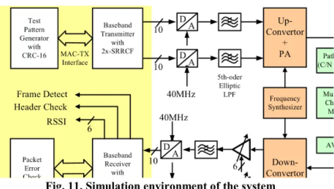
Modern communication systems adopt more complex techniques and specifications, and therefore there are many modes to be selected: modulation, coding, payload length, etc; moreover, operating at undetermined environment, the systems face problems to estimate random parameters under different noise level and channel conditions, and need hundreds of packets to be tested for PER under one condition. All these factors mentioned previously make it very difficult to use only test patterns to verify the design. Besides, it is important to consider relation with analog and RF components. Therefore an integrated simulation platform shown in Fig. 11 is adopted to co-simulate baseband, analog and RF signals. For PER testing the transmit sequence is generated and coded with CRC-16, and then the MAC-to-TX interface serves to move the data from MAC to transmitter. After coding and modulation in transmitter, the data signal conforms to OFDM WLAN specification and outputs with 2x over-sample (40 MHz/sample) with 10-b resolution. The LPFs after DAC use 5th-order elliptic filter to remove duplicate spectra but result in nonlinear phase response and transmission ripples, which can
Coarse CFO Compensation
4 Fine CFO Estimate
4 Fine CFO Compensation
Short GI2 L1 L2 Header Payload
FFT Processing L1 L2 Header 4 L1 L2 Header L1 L2 Header 113 8 Header Demapping 1 Deinterleaving 48 30 Decoding Processing End < 320 cycles (4 OFDM symbols) Payload Payload Payload Payload Equalization Time domain Frequency Domain
Total Latency cycles:
4+128+4+4+113+(-5x12)+8+1+48+30 = 280 (-5x12): reduced latency cycles by STC
128 Symbol Timing Detection
-5x12 = -60 STC Packet End Coarse CFO Compensation 4 Fine CFO Estimate
4 Fine CFO Compensation
Short GI2 L1 L2 Header Payload
FFT Processing L1 L2 Header 4 L1 L2 Header L1 L2 Header 113 8 Header Demapping 1 Deinterleaving 48 30 Decoding Processing End < 320 cycles (4 OFDM symbols) Payload Payload Payload Payload Equalization Time domain Frequency Domain
Total Latency cycles:
4+128+4+4+113+(-5x12)+8+1+48+30 = 280 (-5x12): reduced latency cycles by STC
128 Symbol Timing Detection
-5x12 = -60 STC
Packet End
Fig. 10. Timing diagram of the receiver
Table 1. Gate count list of the baseband processor
Inner Receiver 74.2K
before FFT CORD IC_1 10.1K
Fram e detection 22.8K
A GC 1.7K
Sym bol tim ing detecton 8.8K
FFT_processor 66.1K
Radix-8 butterfly 7.8K Com plex m ultiplier 5.9K
Inner Receiver 68.8K
after FFT CORD IC_2 14.4K
Phase tracking 25.4K CSI dem apping 9.1K
O uter Receiver 178.5K deinterleaver 35K depuncture 0.3K A CS x 3 98.1K traceback 42.7K SRRCF19 10.2K TX and Test 21.9K Total 424.2K D A D A D A 6 10 10 10 Up-Convertor + PA Baseband Transmitter with 2x-SRRCF 40MHz 5th-oder Elliptic LPF Test Pattern Generator with CRC-16 MAC-TX Interface Down-Convertor Mul Ch M AW Baseband Receiver with Packet Error Check Frequency Synthesizer 40MHz RSSI 6 Header Check Frame Detect Path (C/N
be viewed as part of channel response. In RF transmitter the quadrature up-converter operates at 2.4GHz or 5GHz band. Both up-converter and down-converter face problems of I/Q mismatch, gain and phase imbalance, and phase noise from local frequency synthesizer; whereas, linear PA must consider efficient back-off based on OFDM signal with larger PAPR. Multipath channel models use ETSI indoor models and exponential decaying models. The C/N controller adjusts attenuation of transmit signal to the power level compared with noise floor, i.e. about -173 dBm/Hz. VGA is controlled by 6-b signal from AGC of the receiver and the adjust range depends on RF front-end components. The baseband receiver outputs a number of indicative signals: Frame Detect, Header Check, and RSSI. The data after decoding are checked by CRC-16 to count PER value. In this environment the baseband processor written in HDL or MATLAB can be simulated in a full transceiver system, considering all determined and random conditions.
B. Simulation results
There are two main methods to evaluate performance of a transceiver system: error vector magnitude (EVM) used for signal processing in the inner receiver, and PER or BER for full transmission including coding and modulation. EVM is calculated from the statistic of error vectors defined as differences between ideal signals and equalized signals before demapping:
∑∑
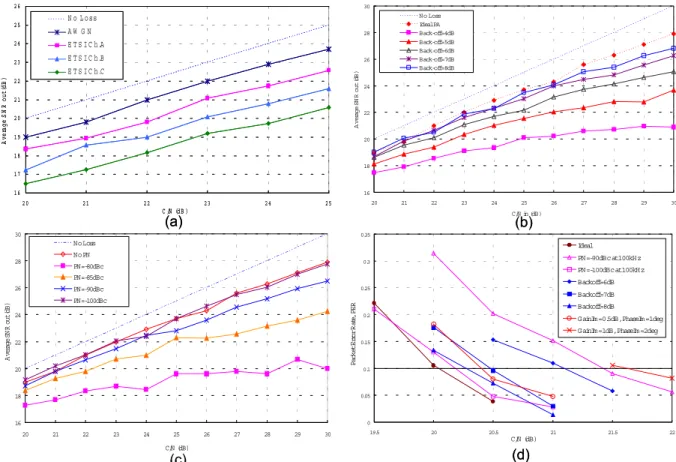
− = l k k l k l d D LK EVM ' , 2 , ~ 1 (31)where L is the number of OFDM symbols, K the number of data sub-channels in an OFDM symbol, and d~l,k the pre-known signal in transmitter. The average SNR value can be acquired from SNR= -20log10(EVM), which means the ratio of signal and noise after processing of inner receiver. The method using EVM or average SNR shortens simulation time because only several packets are required. Fig. 12 shows SNR before demapping for 64QAM with 3/4 coding rate under different testing conditions: (a) AWGN and ETSI Channel A, B, and C (NLOS 50, 100, and 150 rms delay spread, respectively) (b) PA back-off defined as difference between input P1dB and
input average power (c) phase noise at 100KHz from local frequency synthesizer. Fig. 12(a) indicates the SNR loss of inner receiver implemented in HDL is about 1 dB under AWGN and larger than 1.5 dB under channel models. In Fig. 12(b) the observed SNR loss is used to select the back-off for PA: back-off larger than 7 dB is close to ideal PA and the practical loss for PER=0.1 is smaller than 0.5 dB as shown in Fig. 12(d). The SNR values in Fig. 12(c) also help to select phase noise: PN=100 dBc is close to the ideal value with practical loss=0.25 dB as shown in Fig. 12(d). To predict the practical C/N value in the transceiver from EVM or average SNR before demapping, the performance on PER and BER in the outer receiver is proposed in Fig. 13 for 8 kinds of data
0 0.05 0.1 0.15 0.2 0.25 0.3 0.35 19.5 20 20.5 21 21.5 22 C/N (dB) P ack et Er ror Ra te, PE R Ideal PN=-90dBc at 100kHz PN=-100dBc at 100kHz Backoff=6dB Backoff=7dB Backoff=8dB GainIm =0.5dB, PhaseIm =1deg GainIm =1dB, PhaseIm =2deg
16 18 20 22 24 26 28 30 20 21 22 23 24 25 26 27 28 29 30 C/N in (dB) Av e rag e SN R out ( dB ) N o Loss Ideal PA Back-off=4dB Back-off=5dB Back-off=6dB Back-off=7dB Back-off=8dB 1 6 1 7 1 8 1 9 2 0 2 1 2 2 2 3 2 4 2 5 2 6 2 0 2 1 2 2 2 3 2 4 2 5 C /N (d B ) A v er age SN R o u t (d B ) N o L o ss A W G N E T S I C h.A E T S I C h.B E T S I C h.C 16 18 20 22 24 26 28 30 20 21 22 23 24 25 26 27 28 29 30 C/N (dB) Av er ag e SN R out ( dB ) No Loss No PN PN=-80dBc PN=-85dBc PN=-90dBc PN=-100dBc (a) (c) (d) (b) 0 0.05 0.1 0.15 0.2 0.25 0.3 0.35 19.5 20 20.5 21 21.5 22 C/N (dB) P ack et Er ror Ra te, PE R Ideal PN=-90dBc at 100kHz PN=-100dBc at 100kHz Backoff=6dB Backoff=7dB Backoff=8dB GainIm =0.5dB, PhaseIm =1deg GainIm =1dB, PhaseIm =2deg
16 18 20 22 24 26 28 30 20 21 22 23 24 25 26 27 28 29 30 C/N in (dB) Av e rag e SN R out ( dB ) N o Loss Ideal PA Back-off=4dB Back-off=5dB Back-off=6dB Back-off=7dB Back-off=8dB 1 6 1 7 1 8 1 9 2 0 2 1 2 2 2 3 2 4 2 5 2 6 2 0 2 1 2 2 2 3 2 4 2 5 C /N (d B ) A v er age SN R o u t (d B ) N o L o ss A W G N E T S I C h.A E T S I C h.B E T S I C h.C 16 18 20 22 24 26 28 30 20 21 22 23 24 25 26 27 28 29 30 C/N (dB) Av er ag e SN R out ( dB ) No Loss No PN PN=-80dBc PN=-85dBc PN=-90dBc PN=-100dBc (a) (c) (d) (b)
Contributed Paper
Manuscript received January 12, 2005 0098 3063/05/$20.00 © 2005 IEEE rates, based on input signal with i.i.d. Gaussian noise.
According to Fig. 13 all SNR values required from data rates and PER=0.1 are listed in the column marked as AWGN in Table 2. For example, the SNR required for 54Mbps is at least
18.5 dB for PER less than 0.1, but the practical C/N required from implementation shown in Fig. 12 (d) is at least 20 dB. Therefore the implementation loss is 1.5 dB, caused from algorithms and quantization in the receiver.
Table 2 also shows the performance for PER=0.1 and 1024 bytes using 4-b soft-decision and CSI method under i.i.d. Rayleigh channel, i.e., each complex-valued symbol before demapping is multiplied by a complex-valued response with real and image parts both as independent Gaussian noise. Under this condition the average SNR required is shown in the column marked as Rayleigh Ch. in Table 2. The columns marked as CSI and CSI gain represent the SNR required using CSI and its improvement. There are 3dB to 6 dB improvement from 6 Mbps to 54 Mbps by use of CSI in the i.i.d. Rayleigh channel.
C. Performance of the design
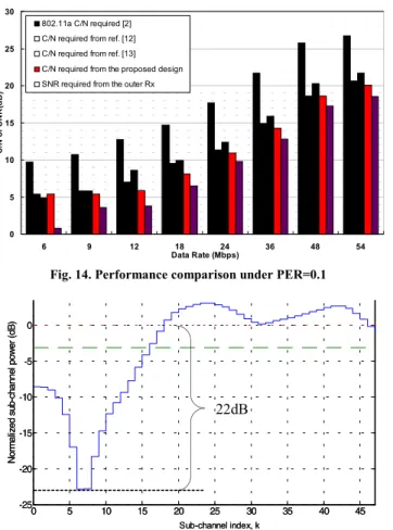
The performance of the baseband receiver is presented in Fig. 14, compared with two reference designs [12]-[13] and 802.11a requirement. The test in this paper is based on PER=0.1 and a packet with 1024 bytes in AWGN, and considers RF and analog effects in the simulation platform. The required C/N in Fig. 14 reveals the receiver design using CORDIC-based architecture performs well under hardware evaluation. On the other hand, to emphasize the benefit using CSI in the demapping, Fig. 15 shows a special case of ETSI
Channel A with some sub-channels suffering extremely deep fading. The channel estimation extracts power values of 48 sub-channels where there are two sub-channels that are 22 dB less than average power as shown in Fig. 15. The simulation reveals that it can not reach PER=0.1 even when C/N=50 dB
for 54Mbps if no CSI is used. But in the design the target is reached when C/N=32 dB. Such special case highlights excellent improvement of CSI method under frequency-selective fading channels.
IV. CONCLUSION
An efficient design for WLAN OFDM receiver is proposed, including algorithm, architecture, and simulation results. Using CORDIC-based design in architecture helps to simplify and unify the algorithm for equalization and synchronization in the inner receiver. Employing CSI improves performance on PER and BER in outer receiver under severer multipath fading channels. The modified demapping combining equalization with CSI eliminates complex-valued divisions and reduces hardware implementation cost. The simulation platform, which co-simulates hardware design with RF, analog parts and channel models, is very useful in verification and performance evaluation. Simulation results and complexity analysis reveal the design is high performance and efficient for OFDM systems. 0 5 10 15 20 25 30 35 40 45 -25 -20 -15 -10 -5 0 5 Sub-channel index, k N o rm a liz ed s ub-ch a nnel p o w e r ( d B ) 22dB 0 5 10 15 20 25 30 35 40 45 -25 -20 -15 -10 -5 0 5 Sub-channel index, k N o rm a liz ed s ub-ch a nnel p o w e r ( d B ) 22dB
Figure 15. Power values of sub-channels from ETSI Channel A 0 5 10 15 20 25 30 6 9 12 18 24 36 48 54 Data Rate (Mbps) C/ N o r S NR( d B ) 802.11a C/N required [2] C/N required from ref. [12] C/N required from ref. [13] C/N required from the proposed design SNR required from the outer Rx
Fig. 14. Performance comparison under PER=0.1
PER=10% PER=10%
Fig. 13. Performance on BER and PER of outer receiver
Table 2. Performance results considering CSI
Rate (M bps) M od. Coding Rate A W GN Rayleigh Ch. CSI CSI G ain
6 BPSK 1/2 0.8 8.6 5.2 3.4 9 BPSK 3/4 3.6 15.8 11.1 4.7 12 Q PSK 1/2 3.8 12.6 8.5 4.1 18 Q PSK 3/4 6.5 20.6 14.6 6 24 16Q A M 1/2 9.8 18.6 14.5 4.1 36 16Q A M 3/4 12.8 27.5 21 6.5 48 64Q A M 2/3 17.3 28.2 23.6 4.6 54 64Q A M 3/4 18.5 32.7 26.5 6.2
ACKNOWLEDGMENT
This work was conducted by the Trans Wireless Technology Laboratory (TWT Lab.) and sponsored jointly by the Ministry of Education and the National Science Council, Taiwan under the contract number NSC-93-2220-E-009-011. The authors also appreciate Ching-Wen Kung, Chia-Hsin Lin and K.H. Lin for their assistance in the design.
REFERENCES
[1] R. van Nee and R. Prasad, OFDM Wireless Multimedia Communications, Artech House, Boston, 2000.
[2] IEEE, “Wireless LAN Medium Access Control and Physical Layer specifications: High-speed physical layer in the 5 GHz band,” P802.11a/D7.0, July 1999.
[3] ETSI, “Digital Video Broadcasting: Framing Structure, Channel coding, and Modulation for Digital Terrestrial Television,” European Telecommunication Standard, EN 300-744, Aug. 1997.
[4] B. Come, et al, “Impact of front-end non-idealities on bit error rate performance of WLAN-OFDM transceivers,” in Proc. of Radio and Wireless Conference, pp. 91-94, Sept. 2000.
[5] M. Speth, D. Daecke and H. Meyr, “Minimum Overhead Burst Synchronization for OFDM Based Broadband Transmission,” in Proc. of GlobeComm, vol. 5, pp. 2777-2782, Nov. 1998.
[6] W. Lee, H. Park, and J. Park, “Viterbi decoding method using channel state information in COFDM system,” IEEE Trans. on Consumer Electronics, vol. 45, no. 3, pp. 533-537, Aug. 1999.
[7] M.R.G. Butler, et al, “Viterbi decoding strategies for 5 GHz wireless LAN systems,” in Proc. of Vehicular Tech. Conf., pp. 77-81, 2001. [8] Y.H. Hu, “CORDIC-based VLSI architectures for digital signal
processing,” IEEE Signal Processing Magazine, vol. 9, pp. 16-35, 1992. [9] H. Zhana, Z. Wang, and S.S. Chandra, “Implementation of frequency
offset correction using CORDIC algorithm for 5 GHz WLAN applications,” in Proc. of ICCS, vol. 2, pp. 983-987, 2002.
[10] M. Speth, S.A. Fechtel, G. Fock, and H. Meyr, “Optimum Receiver Design for Wireless Broad-Band Systems Using OFDM-Part I,” IEEE Trans. on Comm, vol. 47, no. 11, pp. 1668-1677, Nov. 1999.
[11] John Terry and Juha Heiskala, OFDM Wireless LANs: A Theoretical and Practical Guide, pp. 51-55, Sams Publishing, Indianapolis, 2002. [12] J. Thomson, et al, “An Integrated 802.11a Baseband and MAC
Processor,” in Proc. of ISSCC, vol. 1, pp. 126-451, Feb. 2002.
[13] T. Fujisawa, et al., “A Single-Chip 802.11a MAC/PHY with a 32-b RISC Processor,” IEEE Journal of Solid-State Circuits, vol. 38, no. 11, pp. 2001-2009, Nov. 2003.
Chia-Sheng Peng (S’99) was born in Nantou, Taiwan,
in 1976 and received his B.S. degree in Electrical Engineering from National Tsing Hua University, HsinChu, Taiwan, in 1998. He is currently working toward the Ph.D. degree in Electronics Engineering, National Chiao Tung University, Hsinchu, Taiwan. His research interests include wireless communication design on algorithm and architecture for synchronization, equalization, and modulation.
Yuan-Shin Chuang was born in Kaohsiung, Taiwan, in
1977. He received the B.S. and M.S. degrees in Electronics Engineering, National Chiao-Tung University, HsinChu, Taiwan, in 2001 and 2003, respectively. He is currently working toward the Ph.D. degree in Electronics Engineering, National Chiao Tung University, Hsinchu, Taiwan. His research interests include circuit design on wireless communication systems.
Kuei-Ann Wen (SM’02) received her B.S., M.S. and
Ph.D. degrees in electrical engineering from National Cheng-Kung University, Taiwan, in 1983, 1985 respectively. She is currently a full Professor in the Dept. of EE at National Chiao Tung University, Taiwan. Dr. Wen's research interests are in the areas of SoC design and VLSI wireless communication circuit/system also including RF circuits and baseband design. She covers and enhances the curriculum for SoC integration, VLSI computing signal processing, and RF wireless communication. Dr. Wen has been involved in several key research projects including advanced IC/VLSI for academic excellence, and technology transfer for successful high-tech. She also set up the research cooperation laboratories with Agilent, Mentor Graphics and Synopsys for the development of wireless SoC design automation as well as the flow for industrial experts. Besides, she leads the Trans. Wireless Technology (TWT) Laboratory sponsored by United Microelectronics Co. (UMC) for the development of advanced CMOS RF. She also serves as president of IP Center and the leader of SoC Center at NCTU.