國 立 交 通 大 學
電信工程學系
博 士 論 文
於通道偏差下單載波及多載波區塊式傳輸
系統之強健式接收機設計
Robust Receiver Design for Single- and
Multi-Carrier Block Transmission Systems
Under Channel Mismatch
研 究 生:林 志 遠
指導教授:李 大 嵩 博士
於通道偏差下單載波及多載波區塊式傳輸
系統之強健式接收機設計
Robust Receiver Design for Single- and
Multi-Carrier Block Transmission Systems
Under Channel Mismatch
研 究 生: 林 志 遠 Student: Chih-Yuan Lin
指導教授: 李 大 嵩 博士 Advisor: Dr. Ta-Sung Lee
國 立 交 通 大 學
電 信 工 程 學 系
博 士 論 文
A Dissertation
Submitted to Institute of Communication Engineering
College of Electrical and Computer Engineering
National Chiao Tung University
in Partial Fulfillment of the Requirements
for the Degree of
Doctor of Philosophy
in
Communication Engineering
May 2007
Hsinchu, Taiwan, R.O.C.
於通道偏差下單載波及多載波區塊式傳輸系統之
強健式接收機設計
學生:林志遠 指導教授:李大嵩 博士
國立交通大學電信工程學系
摘要
多輸入多輸出正交分頻多工(MIMO-OFDM)系統及多輸入多輸出單載波迴旋前綴 (MIMO SC-CP)系統能非常有效地補償頻率選擇性衰減及支援高資料傳輸率,因此已獲得 許多系統設計者的注意,在本篇論文中,吾人將分別針對上述兩種系統在特定的通訊環境中 設計接收機架構。在 MIMO-OFDM 系統部分,吾人考慮 CP 長度比通道階數(Channel Order) 短的通訊環境,首先針對單輸入多出輸出(SIMO)模式進行設計,吾人聯合利用接收端的空 間及頻率資源提出一個能有效地消除 CP 不足所造成之內符碼干擾(ISI)及內載波干擾(ICI) 的強制最佳化(Constrained Optimization)線性等化器,其最佳化問題在等效的無強制 (Unconstrained)廣義旁波帶消除(GSC)機制下進行求解,之後吾人再將所提出之 GSC 等 化器架構推廣至 MIMO 模式。除此之外,吾人進一步假設接收端無法得知精確之通道參數而 需採用最小平方(LS)技術進行估測,並提出利用擾動分析(Perturbation Analysis)技術將 通道估計錯誤之效應明確地併入 GSC 系統模型,這使得 LS 通道誤差之特性能被應用,藉以 推導出一個能對抗通道估計錯誤的封閉(Closed-Form)強健解。吾人亦推導出此強健式等化 器的近似輸出訊號干擾雜訊比(SINR),由此結果可看出相較於非強解健解的一些優點。 在 MIMO SC-CP 系統部分,吾人考慮一個時變通道環境,同時假設通道參數亦採用 LS 技術估測而得。因為通道在時間上的變化會破壞頻域訊號間的正交性,使得低複雜度之各頻 (Per-Tone)等化機制無法實現,所以在頻域處理訊號將不再具有優勢。因此,吾人提出直接 於時域中處理訊號,於時域中,吾人發現訊號特徵矩陣能夠被分為數個擁有正交元素的群組, 能自然地被用來設計群組式(Group-Wise)訊號偵測技術,為了實現此特性吾人提出一個 GSC 接收機,其能同時抑制通道時間變化與通道估計錯誤所產生之通道偏差效應。由驗證顯示吾 人於 MIMO-OFDM 系統中針對 GSC 所設計的擾動分析數學架構亦能將本部分所考慮的通道 偏差併入系統方程式中,基於通道時間變化與通道估計錯誤的統計假設吾人亦可推導出一個 封閉(Closed-Form)強健解。透過一些數值範例可證實吾人所提出之接收機架構在所考慮的 通訊環境中效能明顯優於現存的方法。Robust Receiver Design for Single- and Multi-Carrier
Block Transmission Systems Under Channel Mismatch
Student: Chih-Yuan Lin Advisor: Dr. Ta-Sung Lee
Department of Communication Engineering
National Chiao Tung University
Abstract
MIMO orthogonal frequency division multiplexing (MIMO-OFDM) and MIMO single-carrier with cyclic prefix (MIMO SC-CP) have drawn a lot of attention since they can effectively compensate frequency selective channels and can support high data rates. In this dissertation, we will design receiver architectures for both of them, each under a specific communication environment. For MIMO-OFDM systems, we consider a scenario that the adopted CP length is shorter than the channel order. By jointly exploiting the receiver spatial and frequency resources, we first propose a constrained optimization based linear equalizer, which can mitigate the resultant inter-symbol interference and inter-carrier interference (ICI) incurred by the insufficient CP insertion, for the SIMO case. The optimization problem is solved under an equivalent unconstrained generalized sidelobe canceller (GSC) setup. Then the proposed GSC-based equalization framework is generalized to the MIMO case. Moreover, in this case we further assume that the channel parameters are not exactly known but are estimated using the least-squares (LS) training technique. We propose to apply the perturbation analysis technique to explicitly incorporate the channel parameter error into the GSC system model; this allows us to exploit the presumed LS channel error properties for deriving a closed-form robust solution against the net detrimental effects caused by the channel estimation errors. A closed-form approximate output SINR expression of the proposed robust equalizer is also derived, based on which some appealing advantages over the non-robust counterpart can be inferred.
For MIMO SC-CP systems, we consider a communication environment that the channel is time-varying, under the assumption that the channel parameters are also estimated via the LS training technique. Since the channel temporal variation destroys the orthogonality between signal components in frequency domain, low-complexity per-tone based equalizations can no longer be realized. As a result, there are no specific advantages of processing signals in frequency domain,
and we propose to directly process signals in time domain. By this way, it is observed that in time domain the signal signatures can be arranged into groups of orthogonal components, leading to a very natural group-wise symbol recovery scheme. To realize this figure of merit, we propose a GSC-based receiver, which also takes into account the mitigation of channel mismatch effects caused by the channel temporal variation and the imperfect estimation. It is shown that the proposed perturbation analysis framework as well enables us to model the channel mismatch effects into the system equation and, in turn, to further exploit the statistical assumptions on the channel temporal variation and the estimation error for deriving a closed-form robust solution. By some numerical examples, it is confirmed that the proposed receiver architectures outperform the existing methods under the respectively considered communication environments.
iv
Acknowledgement
Foremost, I would like to thank my advisor Prof. Ta-Sung Lee for providing me with the opportunity to complete my Ph.D. dissertation at National Chiao Tung University. I learned much from him to improve my working and research styles. I especially want to thank Dr. Jwo-Yuh Wu, whose support made my dissertation work possible. I am very grateful for his motivation, enthusiasm, and immense knowledge in matrix algebra.
I also want to thank the former members of the Communication System Design and Signal Processing (CSDSP) Lab: Dr. Juinn-Horng Deng, Dr. Gau-Joe Lin, and Dr. Chung-Lien Ho for giving me an introduction into the CSDSP Lab and for sharing their knowledge. Thank also goes to my present student colleagues: Fang-Shuo Tseng and Wen-Fang Yang for their inspiring discussions.
Finally, I thank my mother Yueh-Yun Lin, younger sister Bei-Yun Lin, younger brother Chih-Sheng Lin, and girl friend Kan-Wen Lin for their faith and support.
Contents
Chinese Abstract
i
English Abstract
ii
Acknowledgement iv
Contents v
List of Figures
viii
List of Tables
x
List of Notations
xi
List of Acronyms
xii
1 Introduction
1
1.1 Basics of OFDM and SC-CP 1
1.2 Basics of Multi-Antenna Systems 3
1.3 Related Literature Review 5
1.4 Main Contributions 7
1.5 Organization of Dissertation 8
2 Low-Complexity Transceiver for CP-Free Multi-Antenna OFDM Systems 10
2.1 Overview 10
2.2 Uplink Signal Model 11
2.3 Channel-Induced Distortion 12 2.4 Proposed GSC-Based Equalizer 13 2.4.1 Multi-Channel Signal Model 13 2.4.2 Equalization Based on ISI Suppression 14
2.4.3 GSC-Based Equalizer 15
2.5 Reduced-Complexity Equalizer Implementation 17 2.5.1 Computation of Blocking Matrix B 17
2.5.2 PA Implementation 18
2.5.3 Computational Complexity 20 2.6 Downlink GSC-Based Pre-Equalization 21
2.6.1 Downlink Signal Model 21
2.6.3 Reduced-Complexity Implementation 24
2.7 Output SINR Performance 25
2.8 Impacts of Channel Correlation 26
2.8.1 0≤ ρ < case 1 27
2.8.2 ρ = case 1 27
2.9 Simulation Results 29
2.10 Summary 32
3 Robust Receiver Design for MIMO-OFDM Under Channel Estimation
Errors 37
3.1 Overview 37
3.2 Preliminary 38
3.2.1 System Model and Basic Assumptions 38 3.2.2 Least-Squares Channel Estimation 40
3.3 ISI-ICI Mitigation 41
3.3.1 Multi-Channel System Representation 41 3.3.2 GSC-Based Interference Suppression: Perfect Channel Knowledge Case 42 3.4 Proposed Robust Solution Against Channel Estimation Error 43
3.4.1 Problem Formulation 43 3.4.2 Estimated Blocking Matrix: A Perturbation Analysis 45
3.4.3 Optimal Solution 47
3.5 Performance Analysis 50
3.5.1 SINR Evaluation 50
3.5.2 Achievable Performance Advantage 52
3.6 Complexity Comparison 54
3.7 Synchronization Issues 55
3.8 Simulation Results 56
3.9 Summary 60
4 Robust Receiver Design for MIMO SC-CP over Time-Varying Dispersive
Channels Under Imperfect Channel Knowledge
68
4.1 Overview 68
4.2 Preliminary 69
4.2.1 System Model and Basic Assumptions 69 4.2.2 Time-Varying Channel Estimation & Equalization 70 4.3 Group-Wise Symbol Detection: Perfect Channel Knowledge 71
4.3.1 Motivation 71
4.4 Proposed Robust GSC Equalizer Against Channel Mismatch 75
4.4.1 Problem Formulation 75
4.4.2 Optimal Solution 77
4.4.3 Associated Discussions 79
4.5 Algorithm Complexity 80
4.6 Channel Order Determination 81
4.7 Simulation Results 82
4.8 Summary 84
5 Conclusions and Future Works
90
5.1 Summary of Dissertation 90
5.2 Future Works 91
Appendix 92
Bibliography 104
List of Figures
Figure 1.1 (a) Classical MCM, and (b) OFDM modulation 1 Figure 1.2 Block diagram of the OFDM transceiver 2 Figure 1.3 Block diagram of the SC-CP transceiver 3 Figure 1.4 Coexistence of the OFDM and SC-CP modulations 3 Figure 1.5 Illustration of a MIMO system 4 Figure 2.1 Illustration of (a) fully adaptive GSC equalizer (b) partially adaptive GSC equalizer 16 Figure 2.2 Illustration of (a) fully adaptive GSC pre-equalizer (b) partially adaptive GSC
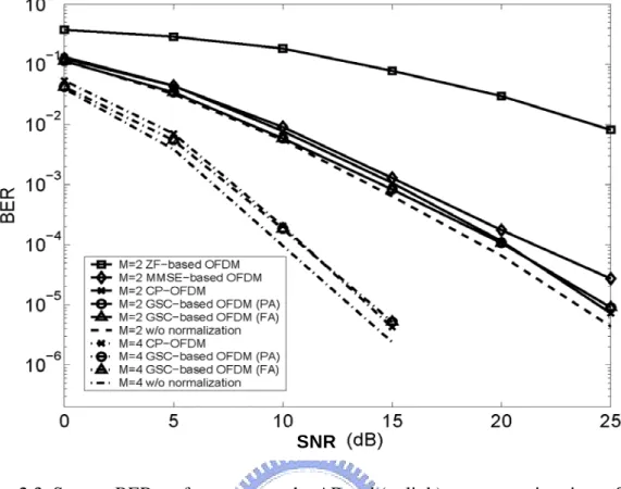
pre-equalizer 22 Figure 2.3 System BER performances at the AP end (uplink) versus receiver input SNR 33
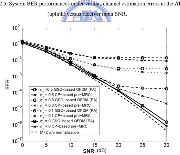
Figure 2.4 System BER performances at the MU end (downlink) versus receiver input SNR 33 Figure 2.5 System BER performances under various channel estimation errors at the AP end
(uplink) versus receiver input SNR 34 Figure 2.6 System BER performances under various channel estimation errors at the MU end
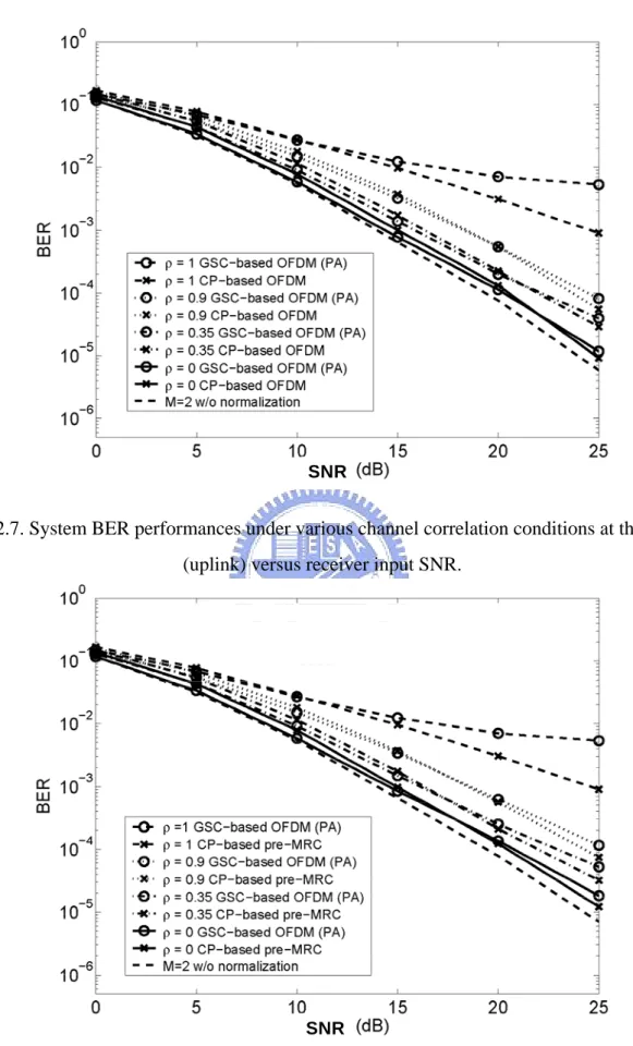
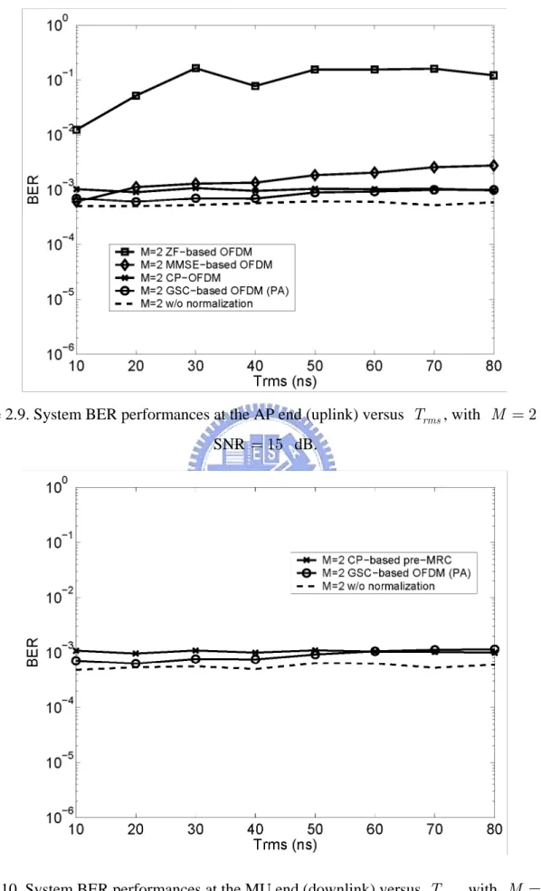
(downlink) versus receiver input SNR 34 Figure 2.7 System BER performances under various channel correlation conditions at the AP end (uplink) versus receiver input SNR 35 Figure 2.8 System BER performances under various channel correlation conditions at the MU end (downlink) versus receiver input SNR 35 Figure 2.9 System BER performances at the AP end (uplink) versus Trms, with M = and 2
SNR =15 dB 36
Figure 2.10 System BER performances at the MU end (downlink) versus Trms, with M = and 2
SNR =15 dB 36
Figure 3.1 Schematic descriptions of (a) the decomposition (3.6) and (b) the relation (3.7) 39
Figure 3.2 BER performances of the three methods (perfect channel knowledge) 61 Figure 3.3 BER performances of the three methods at various channel orders with SNR =20
Figure 3.4 BER performances of the three methods at various CP lengths with SNR =20 dB (perfect channel knowledge) 62 Figure 3.5 BER performances of the three methods (LS channel estimate) 63 Figure 3.6 BER performances of the three methods at various channel orders with SNR =20
dB (LS channel estimate) 63
Figure 3.7 BER performances of the three methods at various CP lengths with SNR =20 dB
(LS channel estimate) 64
Figure 3.8 BER performances of the three methods with distinct subchannel orders (perfect
channel knowledge) 64
Figure 3.9 BER performances of the three methods with distinct subchannel orders (LS channel
estimate) 65 Figure 3.10 SINR performances of the optimal and suboptimal DL solutions 65
Figure 3.11 Output SINR at different transmit powers in the training phase 66 Figure 3.12 SINR gain at different transmit powers in the training phase 66
Figure 3.13 Output SINR at different regularization factors γ (P =2) 67 Figure 3.14 Output SINR at different regularization factors γ (P =14) 67 Figure 4.1 A schematic description of the orthogonality condition (4.9) with L = 3 72
Figure 4.2 BER performances of the proposed method with and without the SIC mechanism (perfect channel knowledge) 87 Figure 4.3 BER performances of the proposed method with and without the SIC mechanism (LS
channel estimate) 87
Figure 4.4 BER performances of the three methods (perfect channel knowledge) 88 Figure 4.5 BER performances of the three methods (LS channel estimate) 88
Figure 4.6 BER performances of the three method with respect to various burst length (LS
channel estimate) 89
List of Tables
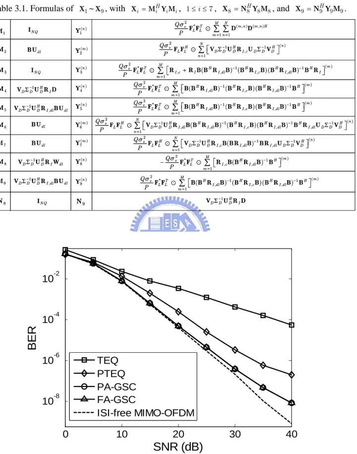
Table 3.1 Formulas of X ~1 X , with 9 Xi = M Y MHi i i , 1≤ ≤i 7 , X8 = N Y M8H 8 8 , and
9 9H 9 9
X = N Y M 61
Table 4.1 Formulae of X( )j ( )t , X( , )i j ( )t , X1( )t ~X4( )t , Y1( )t ~Y3( )t , and Re( )t 86 Table 4.2 Flop count comparison 86
List of Notations
m
C set of m-dimensional complex vectors
Cm n×
set of m× complex matrices n
T
X transpose of matrix X
*
X complex conjugate of X
H
X complex conjugate transpose of X ,
i j
X ( , )i j th entry of the matrix X
x vector two-norm
X matrix Frobenius norm ( )
Tr X trace of the matrix X
: matrix Hadamard product ⊗ matrix Kronecker product
{ }
E y expected value of the random variable y
m I m m× identity matrix m 0 m m× zero matrix m n× 0 m n× zero matrix { }
diag x m m× diagonal matrix with the elements of the vector x on the main
diagonal
1
{ ,..., m}
Diag C C block diagonal matrix with the diagonal block submatrices C , p
List of Acronyms
AP access point BER bit error rate
V-BLAST vertical Bell Laboratories layered Space-Time CP cyclic prefix
DL diagonal loading
FDE frequency-domain equalization FFT fast Fourier transform
GSC generalized sidelobe canceller ICI intercarrier interference IFFT inverse fast Fourier transform ISI inter-symbol interference LS least-squares
LSFE layered space-frequency equalization MCM multicarrier modulation
MIMO multi-input multi-output ML maximum likelihood MMSE minimum mean square error MU mobile unit
OFDM orthogonal frequency division multiplexing PA partial adaptivity
PAR peak-to-average ratio
PIC parallel interference cancellation pre-MRC pre-maximal ratio combining
PTEQ per-tone equalization RHS right-hand-side
RR reduced-rank
SC-CP single-carrier with cyclic prefix
SIC successive interference cancellation SIMO single-input multi-output
SIR signal-to-interference ratio
SINR signal to interference-plus-noise ratio SM spatial multiplexing
STC space-time coding
TEQ time-domain equalization TIR target impulse response
Chapter 1
Introduction
In this introductory chapter, some background materials about block transmission schemes and multi-antenna systems are presented. What follow up are the literature survey, dissertation contributions and an overview of this dissertation.
1.1 Basics of OFDM and SC-CP
Orthogonal frequency division multiplexing (OFDM) [49], [71] is a kind of multicarrier modulation (MCM) scheme. Unlike the classical MCM, in which guard bands are required to separate the different subcarriers (see Figure 1.1(a)), the orthogonality nature of the OFDM subcarriers allows their sidebands to overlap (see Figure 1.2(b)). This makes OFDM the most spectrally efficient among the MCM schemes.
(a) (b)
(a) (b)
Figure 1.1. (a) Classical MCM, and (b) OFDM modulation.
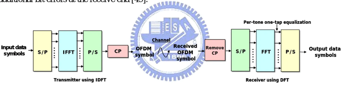
In practical applications of the OFDM modulation, the transmitter segments the signal streams into blocks, which are block-wise fed into the IFFT device. Prior to transmission, a cyclic prefix (CP) is inserted in front of each post-IFFT signal block [71]. At the receiver the CP portion should be discarded before any signal processing starts. As long as CP length is longer than the channel order, the inter-symbol interference (ISI) coming from the previous block is removed, and, moreover, the delayed replicas of an OFDM block are ensured to always have an integer number of cycles within the FFT interval, such that orthogonality between subcarriers is preserved. The
receiver then can only use the FFT device followed by the per-tone one-tap equalizers to recover the transmitted OFDM block [71] (the overall transceiver architecture is shown in Figure 1.2). Due to its simplicity and robustness against frequency selective channels, the OFDM modulation recently has been adopted in a lot of commercial communication systems, such as DAB, DVB and 802.11a/g WLAN. Furthermore, the lately established IEEE 802.16 standard [66], [81] also adopts OFDM in its PHY layer. The main advantage of OFDM comes from the insertion of CP, but, however, the presence of CP could greatly decrease the effective data rate; for example, in the IEEE 802.11a standard, 25% spectral resource is wasted due to the CP insertion. In addition, another fundamental drawback of OFDM is high peak-to-average ratio (PAR) of the transmitted signal, which would incur high clipping rate: each signal sample that is beyond the saturation limit of the power amplifier suffers clipping to this limit value. This leads to non-linear signal distortion and creates additional bit errors at the receive end [49].
OFDM symbol S/P S/P Input data symbols …. . IFFTIFFT P/SP/S CPCP …..
Transmitter using IDFT
Output data symbols S/P S/P Received OFDM symbol …… FFT FFT P/SP/S Remove CP …… Receiver using DFT Per-tone one-tap equalization
Channel OFDM symbol S/P S/P Input data symbols …. . IFFTIFFT P/SP/S CPCP …..
Transmitter using IDFT
Output data symbols S/P S/P Received OFDM symbol …… FFT FFT P/SP/S Remove CP …… Receiver using DFT Per-tone one-tap equalization
Channel
Figure 1.2. Block diagram of the OFDM transceiver.
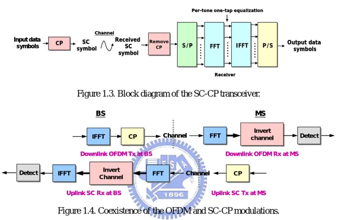
An alternative block transmission scheme is called as single-carrier with cyclic prefix (SC-CP) [19], [20] (see Figure 1.3). With the CP length longer than the channel delay spread, it allows to use the low-complexity one-tap frequency-domain equalization (FDE) to compensate the negative effects caused by frequency-selective channels. Furthermore, since SC-CP system alleviates the IFFT operation (and hence avoids the coherent superposition of the signal samples) at the transmitter, the PAR of SC-CP signals is essentially much lower than that of OFDM signals. In summary, SC-CP has similar performance, bandwidth efficiency, and low signal processing complexity as OFDM, but with much lower signal PAR. The next-generation wireless communication standard, like 3GPP-LTE [17], [45], has considered the coexistence of OFDM and SC-CP in a system: OFDM is used in the downlink transmission and SC-CP accounts for the uplink
counterpart (see Figure 1.4) [45]. Such a deployment leads to two advantages: 1) shifts most signal processing complexity to the base station (two IFFTs and one FFT at the base station, but only one FFT at the mobile station), and 2) allows the power amplifier at the battery-driven mobile station to work more efficiently (since SC-CP has relatively lower signal PAR).
SC symbol Input data
symbols CPCP S/PS/P Output data symbols
Received SC symbol …… IFFT IFFT P/SP/S Remove CP …… Receiver
Per-tone one-tap equalization
Channel FFT FFT …… SC symbol Input data
symbols CPCP S/PS/P Output data symbols
Received SC symbol …… IFFT IFFT P/SP/S Remove CP …… Receiver
Per-tone one-tap equalization
Channel
FFT FFT
……
Figure 1.3. Block diagram of the SC-CP transceiver.
IFFT
IFFT CPCP FFTFFT Invert channel
Invert
channel DetectDetect
IFFT IFFT Detect Detect Invert Channel Invert Channel FFTFFT CPCP Channel Channel BS MS
Downlink OFDM Tx at BS Downlink OFDM Rx at MS
Uplink SC Rx at BS Uplink SC Tx at MS
IFFT
IFFT CPCP FFTFFT Invert channel
Invert
channel DetectDetect
IFFT IFFT Detect Detect Invert Channel Invert Channel FFTFFT CPCP Channel Channel BS MS
Downlink OFDM Tx at BS Downlink OFDM Rx at MS
Uplink SC Rx at BS Uplink SC Tx at MS
Figure 1.4. Coexistence of the OFDM and SC-CP modulations.
1.2 Basics of Multi-Antenna Systems
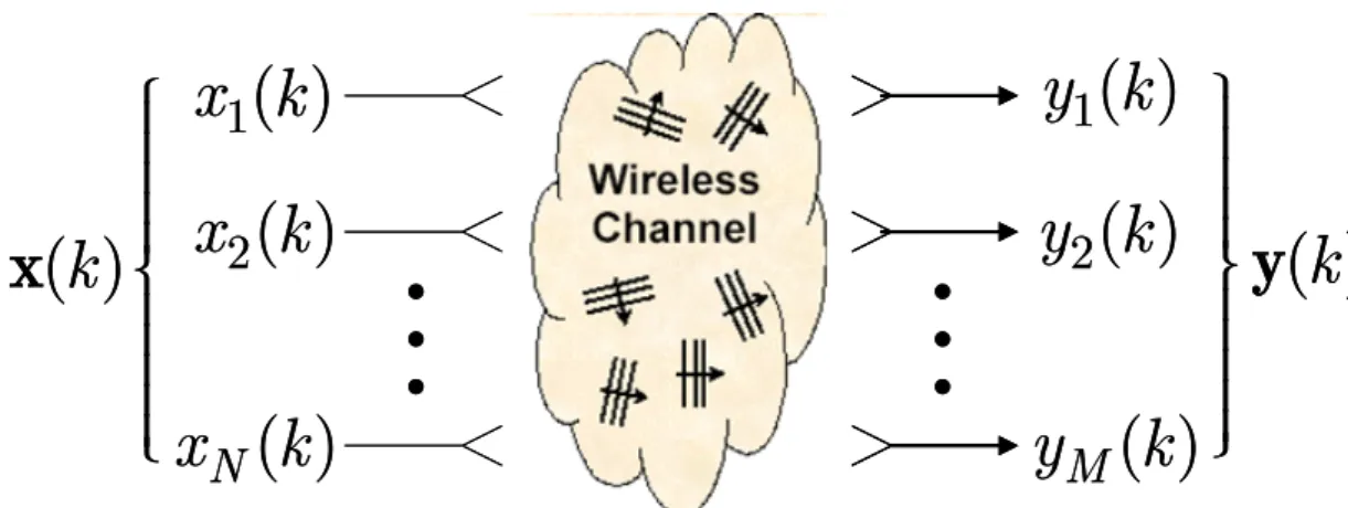
Multiple antennas, as is widely known, can offer an additional antenna gain for various specific tasks. If a multiuser system is equipped with an antenna array at the base station, user terminals can transmit and receive with a smaller gain, leading to lower system interference level and thus larger system capacity. Moreover, multi-antenna array can also offer a much larger degrees-of-freedom for interference suppression. This certainly results in a better system output SINR performance compared with the single-antenna system. Recent theoretical results show that if transmit and receive ends are respectively with M and N antennas, a.k.a., multiple-input multiple-output (MIMO) systems (see Figure 1.5), the point-to-point system capacity can linearly increase with min(M, N) [10]. As a result, the MIMO transmission method has been recognized as one promising solution to achieve high spectral efficiency and link quality, which are believed to be
two major requirements of the next-generation wireless networks. The MIMO research topics are generally categorized into two types: 1) spatial multiplexing (SM) and 2) diversity techniques. A well established SM scheme is known as Bell Laboratories layered Space-Time (BLAST) [82]. At the transmitter multiple independent data streams are simultaneously transmitted via different antenna branches and are detected at the receiver based on their unique spatial signatures. Intuitively, SM technique creates several parallel spatial transmission links so as to increase data rate. Such a system setup can significantly increase system spectral efficiency without the need of increasing transmit power and system bandwidth. On the other hand, the well-known diversity techniques are the space-time coding (STC) schemes [4], [29], [70], in which the transmitted symbols are appropriately mapped into multiple transmit antennas. The receiver then can exploit the artificially induced signal redundancy to obtain diversity gain. Recently, MIMO schemes are usually combined with the OFDM or the SC-CP modulation, a.k.a., MIMO-OFDM [51] or MIMO SC-CP [15], [85], such that the system has a two-fold advantage (coming from MIMO and OFDM (or SC-CP)). MIMO-OFDM and MIMO SC-CP are widely believed to play important roles in the next-generation wireless communication systems, since they can efficiently combat frequency-selective channels and can support high data rates. The next-generation wireless standards, like IEEE 802.16 [66], [81] and 3GPP-LTE [17], [45], have also respectively included them into the specifications.
#
#
1
( )
x k
2
( )
x k
( )
N
x k
1
( )
y k
2
( )
y k
( )
M
y
k
( )
k
⎧⎪⎪
⎪⎪
⎪⎨
⎪⎪
⎪⎪
⎪⎩
x
( )
k
⎫⎪⎪
⎪⎪
⎪⎬
⎪⎪
⎪⎪
⎪⎭
y
#
#
1
( )
x k
2
( )
x k
( )
N
x k
1
( )
y k
2
( )
y k
( )
M
y
k
( )
k
⎧⎪⎪
⎪⎪
⎪⎨
⎪⎪
⎪⎪
⎪⎩
x
( )
k
⎫⎪⎪
⎪⎪
⎪⎬
⎪⎪
⎪⎪
⎪⎭
y
1.3 Related Literature Review
The conventional OFDM systems rely on the insertion of CP to remove the channel-induced ISI, leading to a very simple one-tap equalization implementation [71]. To further boost the effective data rate, a natural strategy is to reduce CP overhead and design a receiver to compensate the resultant negative effects. The time-domain equalization (TEQ) techniques have been extensively studied for discrete multi-tone systems. In these approaches, a time-domain equalizer is employed to properly squeeze the channel impulse response (CIR) to be a prescribed target impulse response (TIR) such that the CP length can be reduced to be the TIR order. In [2] and [65], minimum mean square error (MMSE) based TEQ are proposed to obtain a composite CIR, which is best close to the desired TIR. In [5] and [46], the maximum shortening-SNR method is proposed to maximize the ratio of the energies of the CIR inside and outside a target window; by properly choosing the window size the undesired ISI can be largely suppressed. A lot of researchers are also based on the so-called bit rate maximization criterion to design TEQ [39], [76]. However, such methods should usually exploit the nonlinear optimization techniques to search the optimal TEQ solution, and thus a globally optimal solution is not always guaranteed. In [37], a semiblind TEQ method, which does not require the CIR and channel noise statistics, is proposed for VDSL systems to maximize the frequency-domain signal-to-interference ratio (SIR). The above described methods are usually based on the offline designs: using the derived equalizer coefficients at the beginning of the communication link once and for all during the whole transmission period. However, such approaches are unable to work well if the channel varies with time. In [77], several adaptive TEQ methods are proposed to track the channel variation, so as to be able to maximize the bit rate as high as possible all the time. For MIMO systems, [1] proposes to design TEQ based on minimizing the average energy of the error sequence between the equalized MIMO CIR and a desired MIMO TIR with shorter memory. As an alternative to the TEQ approach, the per-tone equalization (PTEQ) [33] transfers the equalization problem from time domain to frequency domain and has better performance than the TEQ methods at the expense of computation complexity.
low-complexity per-tone FDE scheme. Such a figure of merit, however, hinges crucially on the time-invariant assumption on the background channels. When the channel is otherwise subject to fast temporal variation, the orthogonality among the signal components in frequency domain will no longer be preserved, and tone-by-tone signal recovery is then rendered impossible. To design communication architectures for block transmission systems under time-varying channels is a hot research topic in recent years. In [59] and [86], a method called intercarrier interference (ICI) self cancellation scheme is proposed for OFDM systems. Based on the observation that the ICI components at the adjacent subcarriers are highly similar, at the transmitter one data symbol is assigned, with judiciously designed weights, to multiple subcarriers, and then at the receiver by linear combination of the signals at those subcarriers the ICI components in the received signal can be mutually cancelled. Such approaches are quite simple but, however, the spectral efficiency is low since multiple subcarriers only carry one data symbol. In [55], a simple MMSE-based linear receiver is proposed, in which a banded approximation to the frequency-domain channel matrix is adopted such that the computation of the MMSE weight matrix can be substantially conserved. The linear receiver can also be combined with the parallel interference cancellation (PIC) mechanism to further improve the system performance [28]. In [68], a two-stage receiver is proposed for OFDM systems: in the first stage a max-SINR filter is exploited to suppress ICI and in the second stage an iterative MMSE detector is used to estimate transmitted source symbols; the two-stage receiver architecture also can be further extended for SC-CP systems [67]. It is noted that, to the best of our knowledge, the receiver design under time-varying channels for MIMO block transmission systems remains scarce in the literature.
Receiver designs are in general based on a crucial assumption that the channel state information is perfectly known at the receiver end. However, it is impossible to achieve this in practice, under either time-invariant channels or time-varying channels. As a result, when channel estimation error appears, the derived solutions are rendered suboptimal. Robust linear receiver design against channel estimation errors has been addressed in the context of multiuser communication [52], [53], [54], [84]. By modeling the channel mismatch as a random variable with
known statistical characteristics, the probability-constrained optimization approach [52], [53] exploits the Gaussianality assumption on the estimation error, and the solution is obtained through linear [52] or nonlinear [53] programming. In [54] and [84], the channel error is, on the other hand, treated as a “deterministic” perturbation. Based on a min-max type formulation, the optimization problem in [54] is solved by using the convex programming technique; the solution in [86] admits a diagonal loading form, with the optimal loading factor determined via an iterative procedure. We note that the deterministic formulation of model error is also used in robust beamformer design [35], [42], [64], [75], in which exact statistical characterization of model uncertainty due to, e.g., array calibration error, unknown antenna coupling effect, etc., is difficult (or even impossible) to track.
1.4 Main Contributions
The contributions of this dissertation are summarized as follows:
1. A generalized sidelobe canceller (GSC) based channel equalization framework is proposed for MIMO-OFDM systems with insufficient CP. By jointly exploiting spatial and frequency resources and based on the block signal representation, the desired signal and the ISI/ICI components in the received signal are respectively characterized by the specific signatures, which allows us to leverage the constrained-optimization technique to suppress the interference part and then extract the desired one. It is shown that the proposed method is able to completely suppress the channel-induced distortion via the space-frequency processing, leading to comparable BER performance to the idea case (with sufficient CP insertion).
2. By exploiting the perturbation analysis technique, we incorporate the detrimental effect caused by channel estimation error into the proposed GSC-based MIMO-OFDM architecture to derive a closed-form robust version against channel mismatch. It is shown that the proposed framework merely requires the knowledge of the first- and second-order error statistics but, unlike [52] and [53], is free from any priori assumptions on the error distributions. An analytical expression of the SINR performance for the robust method is derived, based on which the proposed robust method is theoretically proven to yield higher output SINR than the non-robust counterpart.
3. A new constrained-optimization based receiver architecture for MIMO SC-CP systems under time-varying channels is proposed. By exploiting the imbedded cyclic-shift structure of the channel matrix, we can realize a low-complexity group-wise symbol detection setup. Moreover, based on the proposed perturbation analysis framework the channel mismatch caused by the channel temporal variation and the estimation error is also considered into the solution equation, leading to a closed-form robust solution. In comparison with the existing methods, it is shown that the proposed method has better BER performance, but only with comparable computation complexity.
1.5 Organization of Dissertation
The remaining of this dissertation is organized as follows.
In Chapter 2, a GSC based equalizer for ISI/ICI suppression is proposed for uplink SIMO OFDM systems without CP. Based on the block representation of the CP-free OFDM system, there is a natural formulation of the ISI/ICI suppression problem under the GSC framework. By further exploiting the signal and ISI/ICI signature matrix structures, a computationally efficient partially adaptive (PA) implementation of the GSC-based equalizer is proposed for complexity reduction. The proposed scheme can be extended for the design of a pre-equalizer, which pre-suppresses the ISI/ICI and realizes CP-free downlink transmission to ease the computational burden of the mobile unit, which is assumed to be equipped with only one antenna.
Chapter 3 generalizes the ISI/ICI suppression scheme proposed in Chapter 2 for MIMO-OFDM systems with variable CP length (shorter than the channel order) and derives an associated robust version against channel estimation error, assuming that the channel parameters are estimated via the commonly used least-squares (LS) training technique. The channel parameter error is explicitly incorporated into the constraint-free GSC system model through the perturbation analysis technique; this allows us to exploit the presumed LS channel error properties for deriving a closed-form solution, and can also facilitate an associated analytic performance analysis. A closed-form approximate SINR expression for the proposed robust scheme is given, and an appealing formula of the achievable SINR improvement over the non-robust counterpart is further specified. Our analytic
results bring out several intrinsic features of the proposed solution.
In Chapter 4, we consider MIMO SC-CP block transmissions over time-varying multipath channels, under the assumption that the channel parameters are not exactly known but are estimated via the LS training technique. While the channel temporal variation is known to negate the tone-by-tone frequency-domain equalization facility, it is otherwise shown that in the time domain the signal signatures can be arranged into groups of orthogonal components, leading to a very natural yet efficient group-by-group symbol recovery scheme. To realize this figure of merit we propose a GSC based receiver which also takes into account the mitigation of channel mismatch effects caused by the channel temporal variation and the imperfect estimation. Based on the robustness analysis framework proposed in Chapter 3, the channel mismatch is directly modeled into the system equations. Then a closed-form solution can be obtained by further exploiting the statistical assumptions on the channel mismatch. Within the considered framework the proposed robust equalizer can be further combined with the successive interference cancellation (SIC) mechanism for further performance enhancement.
Chapter 2
Low-Complexity Transceiver for CP-Free
Multi-Antenna OFDM Systems
2.1 Overview
Conventional OFDM transmission relies on the insertion of CP to remove the channel induced ISI and ICI, leading to a very simple one-tap equalization implementation [71]. The presence of CP, however, greatly decreases the effective data rate; for example, in the IEEE 802.11a standard, 25 % spectral resource is wasted due to the CP insertion. In recently proposed WLAN systems, multiple antennas are suggested to be employed at the access point (AP) to provide the receive diversity or beamforming gain for enhancing the link quality. Multiple receive antennas, as is widely known, can offer an additional antenna gain for interference suppression. As a result, a natural approach to improving the spectral efficiency in OFDM systems would be to consider CP-free transmission and exploit the multi-antenna resource for combating the channel-induced distortion.
In this chapter, we will propose a multi-antenna transceiver architecture for the CP-free OFDM systems to jointly suppress ISI and ICI. We consider that multiple antennas are equipped at the AP and a single antenna at the mobile unit (MU). In the uplink stage, the degrees-of-freedom offered by multiple receive antennas and their associated subcarriers are exploited for ISI and ICI suppression based on the constrained-optimization technique. The optimization problem is reformulated into an unconstrained one via the GSC principle. The proposed CP-free GSC-based solution can compensate the channel distortion and enhance the data rate, at the expense of increased receiver complexity as compared with the conventional CP-based systems. To mend this penalty, we propose a partial adaptivity (PA) GSC scheme, which involves a series of reduced rank processing [22], [25], for complexity reduction. In time division duplex OFDM systems over slowly time-varying channel, the AP can pre-equalize the ISI/ICI based on the channel knowledge estimated in the uplink stage so as to relieve the MU's computational burden. Since the downlink stage is the dual operation of the
uplink stage, the GSC method is again a natural candidate for the pre-equalizer design based on the block transmission system model. The proposed GSC-based pre-equalizer, which enjoys the same figure of merits as in the uplink counterpart, is shown to effectively pre-suppress the ISI/ICI.
2.2 Uplink Signal Model
We consider the discrete-time baseband model of a multi-antenna CP-free OFDM system with
Q subcarriers and M receive antennas. The source symbol sequence ( )s n is segmented to
obtain consecutive Q × symbol blocks. The kth one among them is 1 s k( )= ⎢⎣⎡s k0( ),...,sQ−1( )k ⎤⎥⎦T, where s kj( )=s kQ( +j), 0≤ ≤j Q− . After the inverse fast Fourier transform (IFFT), we 1 obtain the Q × OFDM symbol 1
1 ( )k = − ( )k
x F s , (2.1)
where x( )k = ⎢⎣⎡x k0( ),...,xQ−1( )k ⎦⎤⎥T , with x kj( )=x kQ( +j) , 0≤ ≤j Q− , and F is the 1
Q-point FFT matrix [79]. The signal ( )xk is then transmitted through the composite channel
( )m ( )
h l , including the response of the cascade connection of the transmitter filter, the channel, and
the receive filter, to the mth receive antenna, 1≤m ≤M. We assume that the channel orders of
( )m ( )
h l 's are all L, which is reasonable since we can always choose L as the largest one among them.
Assuming that the transmitter is synchronized with the receiver, the Q × received data vector of 1 the mth antenna branch, in terms of the block data model [79], is
( ) ( ) 1 ( ) 1 ( )
0 1
( ) ( ) ( 1) ( )
m k = m − k + m − k− + m k
r H F s H F s n , (2.2)
in which H( )0m ∈ Q Q× is a lower triangular Toeplitz matrix with ( )m (0),..., ( )m ( ), 0,..., 0T
h h L
⎡ ⎤
⎢ ⎥
⎣ ⎦ (2.3)
as its first column, H( )1m ∈ Q Q× is an upper triangular Toeplitz matrix with ( ) ( )
0,..., 0,h m( ),...,L hm (1)
⎡ ⎤
⎢ ⎥
⎣ ⎦ (2.4)
as its first row, and n( )m ( )k is the noise vector. The following assumptions are made in the sequel: 1. The source symbols ( )s n are zero mean, uncorrelated, and E s n s n
{
( ) ( )1 * 2}
=δ(
n1−n2)
,where E y denotes the expectation of the random variable y , and (.){ } δ is the Kronecker delta function.
2. The channel taps h( )m ( )l are modelded as i.i.d. zero-mean complex Gaussian random variables with variance σl2 over m and l.
3. The elements of n( )m ( )k 's are modeled as AWGN, for 1≤m≤M, with the same power 2
v
σ .
4. Perfect channel knowledge is available at the AP.
2.3 Channel-Induced Distortion
Based on the block system model, this section characterizes the channel-induced interference for a CP-free OFDM system. From (2.3) and (2.4), it is easy to verify that the matrix
( ) ( )
0 1
m + m ∈ Q Q×
H H is a circulant matrix with the first row equal to ( )m (0),..., 0, ( )m( ),..., ( )m(1)
h h L h
⎡ ⎤
⎢ ⎥
⎣ ⎦ . This suggests that we can rewrite the block signal model (2.2) as
(
)
(
)
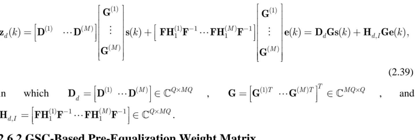
( ) ( ) ( ) 1 ( ) 1 ( ) 0 1 1 ( ) ( ) ( 1) ( ) ( ) m k = m + m − k + m − k− − k + m k r H H F s H F s s n . (2.5)The first term on the right-hand-side of (2.5), which depends entirely on the currently transmitted OFDM symbol, has the appealing property that the signature matrix is circulant. The second term, on the other hand, shows a penalty of removing CP: it accounts for the multipath induced distortion and can cause loss of the orthogonality among subcarriers. From (2.5), we directly obtain the corresponding frequency-domain description
( ) ( ) ( ) ( ) 1 ( ) 1 ( )
0 1 1
( ) ( ) ( ) ( ) ( ( 1) ( )) ( )
m k = m k = m + m − k + m − k− − k + m k
z Fr F H H F s FH F s s Fn . (2.6) Since H( )0m +H( )1m is circulant, the model (2.6) reduces to
( ) ( ) ( ) 1 ( )
1
( ) ( ) ( ) ( )
m k = m k + m − k + m k
z D s FH F e Fn , (2.7) where D( )m ∈ Q Q× is the diagonal matrix with the qth diagonal entry being the channel frequency response evaluated at the qth subcarrier of the mth receive antenna and ( )ek =s(k − −1) s( )k induces the ISI/ICI perturbation. Compared with the time-domain expression (2.5) (or (2.2)), the
frequency-domain model (2.7) has two appealing properties. First, the desired signals are decoupled. In particular, the diagonal nature of the signal signature D( )m will impose certain structure that can simplify the computation of the GSC equalizer parameters. Second, the frequency-domain perturbation is specified by the interference signature matrix FH F( )1m −1 (see (2.7)). This in turn implies that the interference subspace is spanned by some columns of the FFT matrix F . This fact can be further exploited for deriving a closed-form PA implementation of the proposed GSC equalizer for complexity reduction. Hence, instead of relying on the time-domain counterpart, we will focus on the frequency-domain model (2.7) in the following discussions.
2.4 Proposed GSC-Based Equalizer
In this section, we collect the data from multiple receive antennas to form a multi-channel system model. By exploiting a special structure inherent in the interference signature matrix, we propose a GSC-based equalizer scheme as well as an associated reduced complexity implementation
2.4.1 Multi-Channel Signal Model
Stacking z( )m ( )k (see (2.7)), 1≤m≤M, from all the receive antennas gives the following 1
MQ × post-FFT multi-channel model
(1) ( ) 1 1 ( ) ( ) ,..., ( ) ( ) ( ) ( ), ( ) I T T M T M I k k k k k k k − ⎡ ⎤⎡⎢ ⎤⎥ ⎡ ⎤ = ⎢⎣ ⎥⎦ = + + = ⎢⎣ ⎥⎢ ⎥+ ⎦ ⎢⎣ ⎥⎦ H s z z z Ds F H F e v D H v e (2.8) in which (1)T ( )M T T MQ Q× ⎡ ⎤ =⎢⎣ ⋅⋅⋅ ⎥⎦ ∈ D D D (2.9) and (1) ( ) 1 1 1 T T M T MQ Q× ⎡ ⎤ =⎢⎣ ⋅⋅⋅ ⎥⎦ ∈ H H H (2.10)
are respectively the concatenated multi-channel signal signature matrix and ISI/ICI inducing channel matrix, F is an M MQ × matrix given by 1 FM =IM ⊗F , with ⊗ denoting the Kronecker product, and ( )vk is the noise component. From (2.4), it can be seen that the nonzero
entries of the upper triangular Toeplitz matrix H( )1m occur only in the last L columns. Since H is 1 obtained by stacking H( )1m , 1≤m ≤M , one on top of another and both F and M F are −1 unitary, the block Toeplitz structure of H immediately implies that the overall ISI/ICI signature 1 matrix, namely, HI , is of rank L. Let V∈ MQ MQ L×( − ) be the matrix whose columns form an orthonormal basis of the left null space of HI. Then, from (2.8) and the fact that V HH I =O , the (MQ−L) 1× ISI-free data model is obtained as
( ) H ( ) H ( ) H ( )
v k = k = k + k
z V z V Ds V v , (2.11)
where (.)H denotes the Hermitian transpose. It is readily observed that if MQ ≥Q+ , one can L completely extract the Q -dimensional desired signal from (2.11). Since the number of subcarriers is typically much larger than the channel order, i.e., Q L , the choice of M ≥ will satisfy the 2 condition.
2.4.2 Equalization Based on ISI Suppression
Based on the ISI-free data model (2.11), one can use various equalization approaches to recover the desired symbols. Since the columns of the matrix V DH ∈ (MQ L Q− ×) are in general not orthogonal (i.e., D VV DH H ≠I , where Q I denotes an n nn × identity matrix), the ISI nulling operation in (2.11) induces ICI and so an additional signal separation procedure is required for recovering the transmitted symbol on each subcarrier. To this end, a linear equalizer
(MQ L Q)
v ∈ − ×
W of the form yv( )k =W zvH v( )k can be applied. One typical solution for W is v the linear zero-forcing (ZF) [24] or minimum mean square error (MMSE) [60] equalizer with the following (MQ−L)× weight matrix: Q
1 ( ) , H H H zf − = W V D D VV D (2.12) or
(
2)
1 . H H H mmse σv MN L − − = + W V DD V I V D (2.13)In case that the channel frequency response undergoes severe fading near some of the FFT grids, and hence some diagonal entries of D are very close to zero, the ZF solution in (2.12) tends to
amplify the noise effect, even if the SNR is high. The MMSE solution (2.13), on the other hand, can attenuate the noise effect but, as compared with the ZF solution (2.12), involves the larger size matrix inversion
(
V DD VH H +σv MN L2I −)
−1 ∈ (MQ L− ×) (MQ L− ). It is noted that this “two-stage” method completely nulls the ISI, but requires extra degrees-of-freedom to suppress the nulling induced ICI. The equalization performance can be further improved if one resorts to other nonlinear method such as the joint maximum likelihood (ML) search [61]. However, the additional performance gain offered by this nonlinear equalizers is obtained at the expense of higher computational complexity. In the next subsection, we propose a GSC-based equalizer for joint ISI and ICI suppression. This method is linear in nature and, by incorporating a PA implementation, the main computations required boil down to inverting an L× matrix. Moreover, as one will see, L numerical simulations show that it can perform better than the above scheme involving ISI nulling followed by ZF or MMSE ICI suppression.2.4.3 GSC-Based Equalizer
To exploit the extra degrees-of-freedom in model (2.8) for interference suppression, a commonly used approach is via constrained optimization [18], [56], [72]. Specifically, we will seek for a linear weighting matrix W∈CMQ Q× which satisfies
H = H
W D D D , (2.14) and minimizes the average output interference-plus-noise power, i.e., E
{
W H eH( I ( )k +v( ))k 2}
. With constraint (2.14), the optimal weight W will linearly combine the desired signal in the maximal-ratio sense (channel matched filtering), and suppress ISI/ICI via minimizing the total output interference energy; the equalized signal will then be approximate to( ) ( )
H k ≈ H k
W z D Ds , (2.15)
which can further low-complexity tone-by-tone signal separation. To solve for the optimal W , an efficient approach is to transform the constrained optimization problem into an unconstrained one via the GSC principle [23], [74]. This amounts to decomposing the weighting matrix into
= −
W D BU , (2.16)
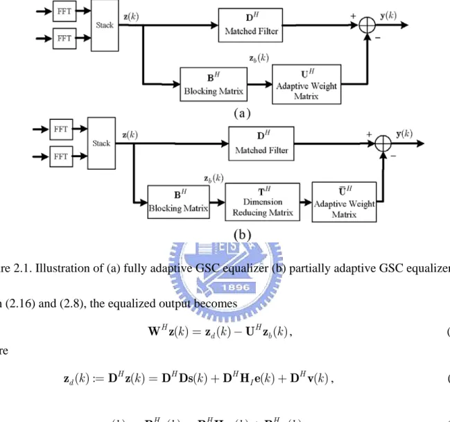
(2.14), B∈CMQ M×( −1)Q is the signal blocking matrix with B DH =O , and U∈C(M−1)Q Q× forms the remaining free parameters to be determined. A schematic description of the GSC is shown in Figure 2.1(a).
Figure 2.1. Illustration of (a) fully adaptive GSC equalizer (b) partially adaptive GSC equalizer. With (2.16) and (2.8), the equalized output becomes
( ) ( ) ( ) H H d b k = k − k W z z U z , (2.17) where ( ) : H ( ) H ( ) H ( ) H ( ) d k = k = k + I k + k z D z D Ds D H e D v , (2.18) and ( ) : H ( ) H ( ) H ( ) b k = k = I k + k z B z B H e B v . (2.19)
Since the matched filtered branch zd( )k is contaminated by ( ) : H ( ) H ( )
I
k = k + k
i D H e D v , (2.20)
to effectively suppress interference equation (2.17) suggests that the matrix U should be chosen to render U zH b( )k as close to ( )i k as possible; more precisely, we can determine U by minimizing the following cost function
{
2}
: ( ) H ( )
b
With (2.19) and (2.20) and by following the standard procedures [9], the optimal weight, denoted by
opt
U , can be shown to satisfy the linear equation
H H in in ⎡ ⎤ = ⎢ ⎥ ⎣B R B U⎦ B R D , (2.22) where 2 : 2 H MQ MQ in = I I +σv MQ ∈ × R H H I C . (2.23) With (2.22), we have
(
H)
1 H opt in in − = U B R B B R D , (2.24)and the optimal GSC weight is thus
(
)
(
H 1 H)
opt MQ in in − = − = − W D BU I B B R B B R D, (2.25)which is commonly referred to as the fully adaptive (FA) GSC equalizer.
2.5 Reduced-Complexity Equalizer Implementation
To obtain the GSC weight matrix W in (2.25), one has to compute the blocking matrix B and to invert the (M −1)Q×(M −1)Q matrix B R BH in . This section proposes a reduced-complexity implementation of the proposed GSC equalizer. In particular, by respectively exploiting the structures of the signal and ISI/ICI signatures D and H , we will show a very I simple approach to computing the blocking matrix B and deriving a low-complexity PA implementation of W .
2.5.1 Computation of Blocking Matrix B
The columns of the blocking matrix B form an orthonormal basis for the left null space of the signal signature D. One typical approach for obtaining B is to perform the SVD on D . Since
D is MQ Q× , the computational burden of the SVD based approach could be prohibitive for a large Q . From (2.9), the matrix D is a concatenation of M diagonal matrices. There is a very simple way of computing B if one can further exploit the block diagonal and sparse structures of
checked that 1 j d and 2 j
d are mutually orthogonal whenever j1 ≠ j2. This observation suggests that we can choose B to be of the form
(1) (M−1) ⎡ ⎤ = ⎢⎣ ⎥⎦ B B B , (2.26) with ( ) (1 ) ( ) T m m T m T MQ Q M ′ = ⎡ ′ ′ ⎤ ∈ × ⎢ ⎥ ⎣ ⎦ B B B , 1≤m′ ≤M − , where 1 Bm(m′), 1≤m≤M , is diagonal. Denote by b(jm′) the jth column of B(m′), 1≤ ≤ . Then the columns of j Q B(m′) are mutually orthogonal. Moreover, it can be directly checked that (m H1) (m2) 0
j k =
b b , for m1 ≠m2, and b(jm H′) dk =0 when j ≠k . As a result, the (M −1)Q columns of the matrix B constructed as in (2.26) form an orthonormal basis for the left null space of D if we choose b(jm′), with b(jm′) =1, to satisfy the orthogonality condition
1 2 ( ) ( ) ( ) 0 0 m H j j m H m j j ′ ⎧⎪ = ⎪⎪ ⎨⎪ = ⎪⎪⎩ b d b b , 1≤m′≤M − , 1 1≤m1 ≠m2 ≤M − , 11 ≤ ≤ . (2.27) j Q
We note that, for a fixed j, only the ((m−1)Q+ -th entries, 1j) ≤m ≤M, in b(jm′) (and hence
j
d ) are nonzero. This implies that (2.27) can be simplified as
(
) (
)
(
)
(
)
1 2 ( )* 1 ( )* ( ) 1 ( 1) ( 1) 0 ( 1) ( 1) 0 M m j j m M m m j j m m Q j m Q j m Q j m Q j ′ = = ⎧⎪⎪ − + − + = ⎪⎪ ⎪⎪⎨ ⎪⎪ − + − + = ⎪⎪ ⎪⎪⎩∑
∑
b d b b , (2.28) with∑
mM=1b(jm′)(
(m−1)Q+j)
2 =1, 1≤m′ ≤M − , 1 1≤m1 ≠m2 ≤M − , 11 ≤ ≤j Q, where b(jm′)( )n denotes the nth entry of b(jm′). Hence, by exploiting the structure of the signal signature matrix D , we can develop B as in (2.26). Instead of performing SVD on D, all we have to do is to pick up the M − M-dimensional solutions (i.e., 1 {b(jm′)( )j ,...,b(jm′)(
(M −1)Q+j)
}, 1≤m′≤M − ) based on the orthogonality condition in (2.28) for each 11 ≤ ≤ . j Q2.5.2 PA Implementation
The computation of the adaptive weight matrix Uopt involves the inversion of the (M −1)Q×(M −1)Q matrix B R BH in . This would lead to a high computational load and poor convergence for real-time implementation whenever Q is large. To resolve this problem, PA GSC
can be incorporated to reduce the size of the adaptive weight matrix as shown as follows. Since H I is of rank L (see Section 2.4.1) and B has orthonormal columns, the post-blocking ISI/ICI signature matrix B HH I ∈ (M−1)Q M×( −1)Q is at most of rank L only. This implies that there are certain redundant components in B H that are irrelevant to the post-blocking ISI/ICI H I information. As a result, it would be plausible to seek for a more compact representation, e.g., through an observation space of dimension L, of the post-blocking ISI/ICI signal. Indeed, if
(M−1)Q L×
∈
T is a basis for the range space of B H [22], [25], then a “refined” post-blocking H I ISI/ICI signal can be obtained by passing the blocked output zb( )k through T , leading to the H following L-dimensional data vector zb( )k =T B H eH H I ( )k +T B vH H ( )k . The reduction in signal dimension via the matrix filtering T can extract the minimal possible information essential for H describing the L-dimensional post-blocking interference subspace. The major advantage of such a data refinement is to allow for the use of a reduced size adaptive weight matrix. In fact, based on
( )
b k
z , it only requires to choose an L× weight matrix U to minimize the cost function Q
{
}
min E ( )k − H H H ( )k 2
U i U T B z , (2.29)
which yields the solution
(
H H)
1 H Hin in
−
=
U T B R BT T B R D. (2.30)
Based on (2.30), the optimal MQ× GSC weight matrix is thus Q
(
H H)
1 H H in in MQ − ⎡ ⎤ = − = ⎢ − ⎥ ⎣ ⎦ W D BTU I BT T B R BT T B R D . (2.31)Compared with (2.25), in which an (M −1)Q×(M −1)Q matrix inversion is needed, the weight matrix defined in (2.31) involves only an L× matrix inversion. This can significantly reduce the L computational complexity since, in practice, the channel order L is quite small as compared with the number of subcarriers Q . The W in (2.31) is often referred to as the PA implementation of the GSC weight (see Figure 2.1(b) for a schematic description).
The remaining task is to find the dimension reducing matrix T , whose columns consist of a basis for the range space of B H , namely, the interference subspace. The rest of this section will H I
show that there is a simple closed-form candidate for such a T . To proceed, the term B H is H I first expanded into
( ) (1) 1 1 1 ( ) ( 1) 1 1 1 M m H m m H I M m M H m m − = − − = ⎡ ⎤ ⎢ ⎥ ⎢ ⎥ ⎢ ⎥ ⎢ ⎥ = ⎢ ⎥ ⎢ ⎥ ⎢ ⎥ ⎢ ⎥ ⎢ ⎥ ⎢ ⎥ ⎣ ⎦
∑
∑
B FH F B H B FH F , (2.32)where we use (2.8) and (2.26). Define Jl ∈ Q Q× , 1≤ ≤ , to be the matrix with zero entries l L except that those on the (Q− + -th upper diagonal are equal to one. Then we can express l 1)
( ) ( ) ( ) 1 1 L m m l l= h l =
∑
H J for 1≤m ≤M, such that 1 1 H N H L I b L H N L− + ⎡ ⎤ ⎢ ⎥ ⎢ ⎥ ⎡ ⎤ ⎢ ⎥ = ⎢⎣ ⋅⋅⋅ ⎥⎦ ⎢ ⎥ = ⎢ ⎥ ⎢ ⎥ ⎢ ⎥ ⎣ ⎦ f B H f f T F f , (2.33) where
(
( ) (1))
(
( ) ( 1))
1 1 1 1 1 1 1 ( ) ,..., ( ) T M L T M L T m H m M H MQ l m j l m j l m j m j h j − + h j − − + × = = = = ⎡ ⎤ ⎢ ⎥ = ⎢ ⎥ ∈ ⎢ ⎥ ⎣∑ ∑
∑ ∑
⎦ f B f B f , (2.34) qf , 1≤ ≤q Q , are the columns of the FFT matrix F , Tb =⎣⎡⎢f1 fL⎦⎤⎥∈ MQ L× , and
1 H L Q L Q Q L × − + ⎡ ⎤ = ⎢⎣ ⎥⎦ ∈
F f f . Based on (2.33), T should form a basis for the range space of b
H ISI
B H . As a result, a natural and immediate choice for the dimension-reducing matrix T is
b
=
T T .
2.5.3 Computational Complexity
This subsection compares the computational complexity (measured in terms of the number of complex multiplications (CM)) of the FA GSC-based equalizer, PA GSC-based equalizer, and MMSE receiver. To obtain the two GSC-based solutions, one shall first compute the matrix
MQ MQ in
×
∈
R (cf. (2.24) and (2.30)). Based on (2.23) and by definition of H in (2.8), we can I express R as in 2 1 1 2 H H n in = M M +σ MQ R F H H F I , (2.35)
where H is defined in (2.10). Equation (2.35) implies that the computation of 1 R can be in implemented using FFT. By further exploiting the sparse structure of H (recalling that the 1 nonzero entries in each submatrix of H all cluster in the upper right corner), the number of flops 1 for computing R is determined as in 2M L2 2logQ2+M L2 3. Based on (2.25) and (2.31), the total approximate flop counts required to compute FA and PA GSC-based solutions are respectively summarized as below: 3 2 2 3 2 2 2 1 5 4 2 ( 2 log ) 3 2 Q FA CM = Q +⎛⎜⎝⎜⎜ M + M + ⎞⎟⎟⎟⎠Q + M L + M L Q, (2.36) and 2 2 3 2 2 2 5 (4 2 ) 2 1 log 2 2 Q PA L CM = M + M Q +⎛⎜⎜⎜⎝⎜⎜⎛⎝⎜M + ⎠⎟⎟⎟⎞L +⎛⎝⎜⎜⎜ M + + ⎟⎞⎟⎠⎟L ⎠⎞⎟⎟⎟⎟Q. (2.37)
For comparison, the total flop count required to obtain the MMSE solution in (2.13) is given as ( )3 ( )2 1 2 2 ( ). 3 MMSE CM = MQ−L + Q MQ−L + MQ MQ−L (2.38)
From (2.36), (2.37) and (2.38), it can be seen that the PA scheme can save about one order of computational load over the FA GSC and MMSE solutions.
2.6 Downlink GSC-Based Pre-Equalization
To relieve the MU complexity, one can resort to the pre-equalization technique. Based on the block system model, this section derives a GSC-based pre-equalizer, which serves as the downlink counterpart of the previous work.
2.6.1 Downlink Signal Model
In the downlink stage, the OFDM symbol ( )s k is first weighted by G( )1, ,… G( )M , respectively for the M transmit antenna branches, and is then transmitted though the ISI channel. Similar to the synchronous block signal model in (2.8), the Q × frequency-domain noise-free received data at 1 the MU is expressed as