Controller Design for Active Noise Cancellation
Headphones Using Experimental Raw Data
Shiang-Hwua Yu and Jwu-Sheng Hu
Abstract—This work presents a practical method of designing
controllers for active noise cancellation (ANC) headphones. Without attempting system identification and perturbation modeling, the headphone system is directly described by a set of frequency-response data. In frequency domain, the controller synthesis problem is formulated as a constrained optimization problem, where theH2 performance objective is minimized with various frequency-dependent constraints. The fixed-order robust controller is thus designed to achieve maximum noise attenua-tion with acceptable stability margins. Further, the method is able to accurately constrain noise amplification outside control bandwidth due to waterbed effect of nonminimum phase plants. This feature is very important for the ANC design to maintain an overall quality of noise reduction.
Index Terms—Acoustic noise, active noise cancellation, feedback
control, headphones.
I. INTRODUCTION
A
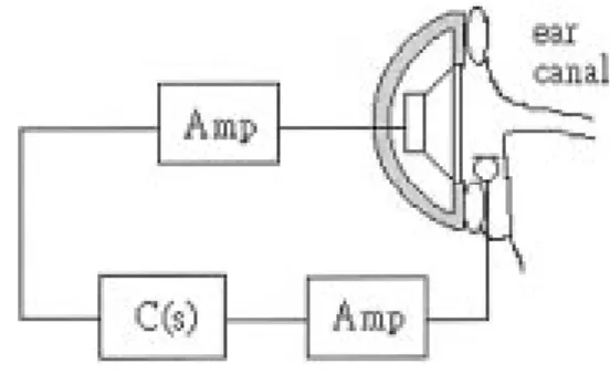
N ACTIVE noise cancellation (ANC) headphone is a spe-cial headphone that protects the ear from harmful noise. Unlike a passive hearing protector, an ANC headphone elim-inates noise by creating another noise of equal amplitude and opposite phase. Fig. 1 illustrates one channel of an ANC head-phone system, which includes a loudspeaker, a closely spaced miniature microphone, amplifiers, and a feedback controller. This configuration was first suggested by Olson and May, 1953 [1]. The aim of this application is to minimize the noise level in the small closure around the ear canal, an action which is exactly the same as a classical disturbance rejection problem in con-trol. To design the feedback controller of the ANC headphone, Wheeler (1986, [2]) employed classical control theory heuris-tically to shape the open-loop frequency response. By using modern control theory, Bai and Lee (1997, [3]) used opti-mization technique to optimally synthesize the robust controller. For the development of ANC systems, see an excellent histor-ical review by Leitch and Tokhi (1987, [4]).Most controller synthesis methods need a reasonably accu-rate plant model for a satisfactory result. An important issue in modeling is determining the parameters of a model, usu-ally in transfer function or state-space form, based on mea-surement data. Additionally, it is also essential to characterize uncertainties appropriately. The uncertainty can be represented
Manuscript received April 26, 2000; revised March 12, 2001. Recommended by Technical Editor H. Peng. This paper was supported by the National Science Council, Taiwan, R.O.C., under Grant NSC89-2213-E-009-127.
The authors are with the Department of Electrical and Control Engineering, National Chiao Tung University, Hsinchu, Taiwan 300, R.O.C. (e-mail: [email protected]).
Publisher Item Identifier S 1083-4435(01)10737-4.
Fig. 1. An ANC headphone.
in either a parametric or nonparametric form. However, vali-dating the model of an ANC headphone system is relatively dif-ficult due to the wide bandwidth requirement, the complexity of system dynamics, and unavoidable variation of acoustic dy-namics. Another important design problem is to translate per-formance requirements in practice into various design criteria. For an ANC headphone, the performance specifications must be carefully imposed in the designs, since human ears are very sensitive to the extra noise produced by the headphone. For a technique like -optimal control design (Zames, [5]; Francis and Zames, [6]), the engineering specifications must be trans-lated into a choice of the weighting functions. However, se-lecting weighting function is difficult, even for moderately com-plex problems. Moreover, the optimization usually results in a very high-order controller. Consequently, some model re-duction techniques are needed. This suboptimal approach raises the question of why the controller’s order should not be fixed in advance. Accordingly, a trend exists to develop computer-aided controller design and fixed-order controller synthesis, and thus reduce the gap between theory and practice in control systems, for example, see Jacques et al. [7], Blanchini and Sznaier [8], and Keel and Bhattacharyya [9].
This work employs a fixed-order controller structure, and the controller is synthesized directly from the frequency-response data of the headphone system. Therefore, the approximated procedures of system identification, uncertainty modeling and controller model reduction are avoided. An norm is employed as a measure to minimize the average power of inter-fering noise. Numerous specifications, such as the gain margin, phase margin, allowable noise amplification and stability robustness, are accurately translated into various frequency-dependent constraints. The controller synthesis problem is thus formulated as a constrained optimization problem, allowing the locally optimal controller to be obtained. The proposed method was found to be particularly useful and effective for an ANC headphone design.
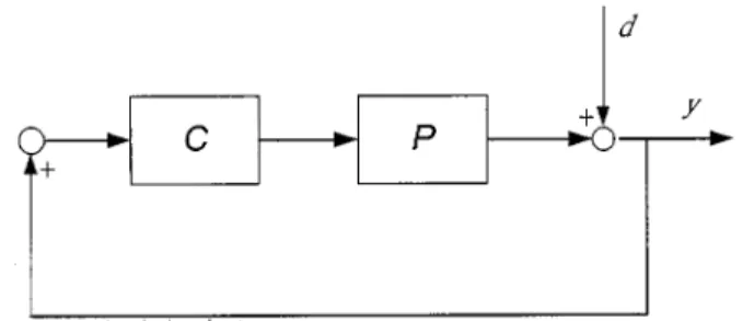
Fig. 2. A feedback control system.
II. PROBLEMSTATEMENT
Consider a classical SISO feedback system in Fig. 2. The plant belongs to , a set of linear time-invariant stable plants, the frequency responses of which are provided. The objective is to synthesize an th-order controller that stabilizes all with some prescribed stability margin and ensures good noise attenuation within the control bandwidth.
The set represents several typical dynamics of a headphone operating under various conditions, or just a few representa-tive plants from a large group of manufacturing headphones. Since headphone systems are stable, the frequency responses of these plants can be obtained by direct measurement. Without attempting to model these plants, the frequency-response data is used directly to synthesize the controller. The synthesis pro-cedure is conducted by first translating the design specifications into the frequency domain constraints. The resulting frequency dependent constraints are then utilized to determine a permitted region in the complex plane, within which the designed open-loop transfer functions must lie. Once the feasible region in the frequency domain is found, the parameterized fixed-order controller may be optimally synthesized to compensate all the plants in such that the resulting loop shapes are in the accept-able region.
III. LOOPSHAPING VIACONSTRAINEDOPTIMIZATION
Assume the frequency responses of a set of stable plants are provided. Finding an th-order controller is desired to achieve both robust performance and robust stability for this set of plants. However, for notational simplicity, the design initially includes a one-plant set , and the generalization
to is straightforward, as shown in
Section V.
Parameterization of an th-Order Controller: To synthesize
controllers via a computer program, a controller parameteriza-tion is first chosen, and all performance specificaparameteriza-tions are then expressed in terms of either the functional objective or func-tional constraints. First, an th-order controller is represented as
(1) The frequency response of this controller is thus
(2)
where
where the symbol denotes the complex conjugate transpose. In this way, an th-order controller can be parameterized in a
vector . Consequently, for the plant ,
the frequency response of the open-loop transfer function is (3) By converting the design specifications into various frequency-dependent restrictions on the open-loop transfer function , the optimal parameter vector can be determined.
Stable Controllers: The controller candidates are restricted
to th-order real rational stable controllers. The designs herein are limited to stable controllers for two reasons. First, unstable controllers are more sensitive to noise and system variation, and thus less favorable in practical applications. Moreover, stable controllers will simplify the design. To ensure the controller stability, all the poles of the controller must have negative real parts. Assume that the denominator of an th-order controller is . According to the Lienard–Chipart cri-terion (see Parks and Hahn [10]), the controller is stable if and only if
(C1) (4)
where and when is even; and
when is odd. And are Hurwitz
de-terminants, expressed as follows:
where the coefficients with indices larger than should be re-placed with zeros. The advantage of the Lienard–Chipart cri-terion is that computing all Hurwitz determinants for some is unnecessary, thus reducing the computational load. Thus the Lienard–Chipart criterion is used to ensure the controller sta-bility.
Stability With a Prescribed Margin: Since the plant and
con-troller are both stable, according to the Nyquist stability crite-rion, the closed-loop system is stable if and only if the Nyquist plots of the open-loop transfer function do not encircle . However, the Nyquist stability criterion is difficult and ineffi-cient for the stability test on a digital computer (Polak [11]).
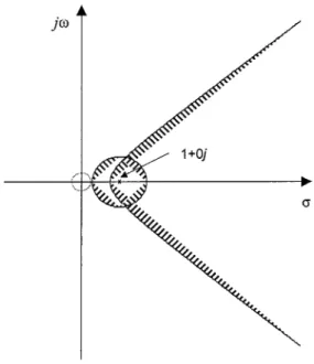
Fig. 3. Different frequency-dependent forbidden and attracting regions in the Nyquist plane.
Hence, the following sufficient stability condition is provided instead:
(C2)
(5) where is a parameter which is connected to the sta-bility margin. This condition creates a hyperbolic bound in the complex plane, as shown in Fig. 3. This bound not only prevents from encircling the critical point , but also provides a stability margin for the feedback system. In this condition, the gain margin GM and phase margin PM would satisfy the fol-lowing relations:
(6)
respectively. Apparently, the smaller the parameter implies a larger stability margin, making the entire system less sensitive to perturbation. This property helps translate the actual require-ment of the stability margin into the choice of the single param-eter .
Noise Attenuation: To obtain good noise attenuation, the
magnitude of sensitivity function must be minimized over the noise bandwidth. Since the sound pressure level is defined by the time-averaged squared value of the sound pressure, an norm is naturally employed as a measure to minimize the average power of interfering noise (Rafaely and Elliott [12]). This requirement can be expressed as the following optimization problem
(7) where is the power spectral density of the noise. This min-imization is equivalent to minimizing the power of the output signal in a feedback system, as shown in Fig. 2. If the noise is in-definite, a bandlimited white noise can be assumed. In this case,
is one over a certain bandwidth and zero beyond.
Water Bed Effect: Since headphone systems are
nonmin-imum phase, another design tradeoff should be considered. Making the magnitude of sensitivity function below one over some frequency interval is known to imply this magnitude exceeds one elsewhere (Francis and Zames [6]; Freudenberg and Looze [13]). Therefore, to avoid excessive noise amplifi-cation, an additional constraint must be included to prevent the magnitude of sensitivity function from growing too large
(C3) (8)
where . This frequency-dependent constraint provides a circular bound with a radius with the center in the complex plane, see Fig. 3. This circular bound ensures that the magnitude of sensitivity function is below . Interestingly, in Fig. 2, the condition (C2) and (C3) together create a new bound of the stability margin
(9)
Stability Robustness to High-Frequency Uncer-tainty: Physical systems generally have some high-frequency
plant uncertainty. For instance, a slight change in the system delay could cause a large phase variation in the high-frequency band. Thus the open-loop gain should be small for stability
(C4) (10)
where . This condition makes the open-loop gain smaller than some prescribed value at the high-frequency band . Thus the system becomes more robust for the high-fre-quency dynamic perturbation. This condition provides a circular attraction region for the high-frequency locus , see the small dotted circle in Fig. 3.
In sum, given the frequency response of the plant, the fixed-order controller can be designed by solving the following con-strained optimization problem:
(11) subject to (C1) (12) (C2) (13) (C3) (14) (C4) (15)
where the design parameters , , and are real numbers in the interval (0, 1). The control problem is characterized by tradeoffs, with different constrained values creating different achievable performance objectives.
IV. APPROXIMATION OF THESOLUTION
The constrained optimization formulated above is a semi-infi-nite programming problem, in which either the number of
vari-Fig. 4. A circuit diagram of an ANC headphone.
ables or number of constraints is infinite, but not both (Polak
et al. [14]). The present case has infinite frequency-dependent
constraints. However, by applying the frequency discretization (see Boyd et al. [15]; Helton and Sideris [16]; Rafaely and El-liott [12]), the resulting approximated problem has finite con-straints, and the integral in (11) is approximated by the Rie-mann summation. The approximated constrained optimization, a typical nonlinear programming problem, is not convex due to the fixed-order controller structure employed herein (Boyd and Craig [17]). Thus, only the local optimum can be obtained. To search for the local optimum, the Recursive Quadratic Program-ming (RQP) method is used. To make the RQP method more ef-ficient and reliable for the complex problem herein, an active set strategy is used. With such strategy, only a subset of the original constraints is used to define the direction finding subproblem at each iteration. This algorithm and various modifications have been extensively developed and discussed in the literature (see Lim and Arora [18]; Gabriele and Beltracchi [19]; Tseng and Arora [20]). Therefore, the numerical implementation details are omitted here.
With numerous frequency samples over the entire frequency band, a good approximation to the original problem can be obtained. However, a particularly large amount of data may in-troduce redundancies in the approximated problem and an extra computational effort may be required to solve the problem. Meanwhile, if too little data is used, the approximated problem may not be sufficiently close to the original one, and, hence, the designs may not guarantee stability and may not meet the performance specifications. A more effective method is to use small spacing frequency-response data to closely approximate the low-frequency responses of the system, and simultaneously use large spacing data to roughly describe the high-frequency responses. Since the open-loop gain will be made small on the sampled frequencies in high-frequency interval, the system will be reasonably less sensitive to high-frequency uncertainty. Hence, it can use large spacing data to describe the high-fre-quency dynamics without courting disaster.
V. FEEDBACKCONTROLLERDESIGNS FOR ANANC HEADPHONE
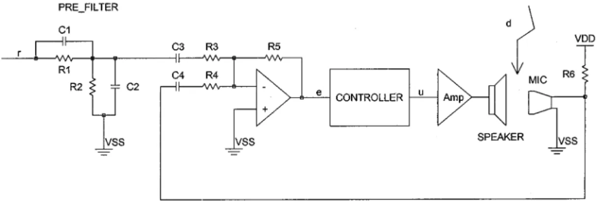
This section applies the proposed method to the controller synthesis for an ANC headphone. A circuit diagram of the ANC headphone is shown in Fig. 4. Two exogenous signals are
in-volved in this system. One is the acoustic noise , which is con-sidered as the disturbance in this system. The other is electrical input signal , which contains desired information, for example, music from a CD player or speech from a mobile phone. In this case, the ANC headphone aims at reproducing the desired signal while attenuating the acoustic noise from outside. The headphone experimented on herein is the Gamma LH 065 stereo headphone. A miniature condenser microphone, used to pick up the sound reaching the entrance of the ear canal, is placed inside the ear cup of the headphone. Capacitors C1–C2 and resistors R1–R2 constitute a simple high-pass prefilter, which is used to compensate the overall feedback system, and minimize the re-producing distortion. C3 and C4 are coupling capacitors. The op-amp along with resistors R3–R5 acts both as a preamplifier and inverting summer, which is responsible for amplification of the microphone signal and summing-up of the signals from the microphone and prefilter. Finally, an audio power amplifier is used to drive the loudspeaker. Inspection of the circuit diagram shows that two main filters, i.e., the prefilter and the feedback controller, are involved. These two filters play vital roles in the performance of the ANC headphone. In this work, the emphasis is placed on the design of the feedback controller.
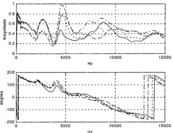
Many factors contribute to uncertainties of the headphone dy-namics, for example, nonlinearity due to large-amplitude exci-tation, parameter variations caused by temperature shifting, and various sound pressure responses for different acoustic environ-ments (for example, slight move of the wearing position or dif-ferent tightness of the headphone’s cup). Among these factors, the variations of acoustic dynamics are the most pronounced. Between the ear and the diaphragm of the headphone there is a small closure. Different wearing position or tightness of the headphone’s cup can change this small closure, thus resulting in different acoustic dynamics. Frequency responses of the uncon-trolled headphone can be measured by first removing the prefilter and feedback controller in Fig. 4, and then applying a sine sweep to the control input node . Meanwhile, the magnitude and phase shift of the response at each frequency are measured at the node . Fig. 5 illustrates four representative frequency responses of the headphone in various wearing positions. The frequency re-sponses differ markedly from one another, mainly because the acoustic dynamics is quite sensitive to any slight change of the small closure around the headphone and the ear canal.
Accordingly, four representative frequency responses in Fig. 5 roughly summarize the possible variations of the plant.
Fig. 5. Four representative frequency responses of the headphone system.
We do not take into account other kinds of plant variations because they are generally small as compared with the vari-ations of acoustic dynamics. This section aims to design feedback controllers to stabilize these representative plants and simultaneously achieve a robust performance. To achieve this, the objective in (11) is replaced by
(16)
where , and , are the
representa-tive plants. Additionally, the open-loop transfer functions corre-sponding to the representative plants should all satisfy the con-straints in (12)–(15) with some constrained values. The min-imization (16) is equivalent to minimizing the average power of cancellation errors associated with different representative plants in the feedback system. To adopt the frequency discretiza-tion method to form the approximated constrained optimizadiscretiza-tion, these four representative frequency responses are sampled, with the sampling period 1 Hz in the frequency interval 1–2000 Hz and 10 Hz in the interval 2000–15 000 Hz. Accordingly, the in-tegral in (16) is approximated by the Riemann summation, and the constraints are evaluated based only on these sampled fre-quencies. With different design parameters, two examples are illustrated below.
Design A—Cancellation of the Bandlimited White Noise: Here, the aim is to maximize the reduction of sound
pressure level for the band-limited white noise in the low-fre-quency audible band from 50–500 Hz. Thus, the weighting sequence is selected to be 1 in the interval 50–500 and zero beyond. The optimization problem is thus equivalent to mini-mizing the average power of sound pressure in the headphone caused by bandlimited white noise, of which the power spectral density is 1 from 50 to 500 Hz and zero outside this interval. Notably, as depicted in Fig. 5, the system is a nonminimum
Fig. 6. Nyquist plots of four representative open-loop transfer functions (Design A).
phased system, making the waterbed effect unavoidable when the sensitivity function is minimized. Nevertheless, the noise amplification over the other frequency interval should not be too large. According to the experiments, an increase of 3 dB in sound pressure level is just noticeable subjectively for most people (see [21, Sec. 1.7]). Therefore, the maximum allowable amplification of interfering noise is chosen as 3 dB. This is a very important constraint. Without this constraint, the feedback loop may run into oscillation due to excessive large loop gain within control bandwidth, and, thus, produce annoying audible sound or inaudible sound. Especially, the inaudible sound at very low frequency may exert force on the eardrum and produce an odd sensation in the ear (the ear cannot hear it but can feel it; that is a strange feeling). Therefore, this 3-dB constraint is very important for avoiding this kind of adverse effect. As for the robust stability, the gain margin is chosen as 10 dB, and the phase margin as 40 . Meanwhile, the maximum open-loop gain over the high-frequency interval 2000–15 000 Hz is set at 0.25. Consequently, the design parameters , , and are 0.9063, 0.7079, and 0.25, respectively, while the order of the controller is set as 4. After solving the nonlinear programming problem, a locally optimal controller is obtained as shown in the equation at the bottom of the page.
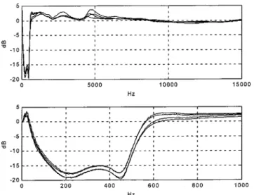
Fig. 6 shows the Nyquist plots of the corresponding open-loop transfer functions for four representative plants, and Fig. 7 plots the magnitudes of the corresponding sensitivity functions in the interval 1–15 000 Hz (above) and in the interval 1–1000 Hz (below). Four Nyquist loci of the open-loop transfer functions, as illustrated in Fig. 6, begin from the origin, then encircle the origin clockwise, run away from the critical point without penetrating the bounds, and finally enters a small circle set for high-frequency robustness. Fig. 7 also illustrates that the magnitudes of these four sensitivity functions are around 15
Fig. 7. The magnitude of four representative sensitivity functions (Design A).
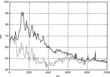
Fig. 8. Noise power spectra in the headphone cavity with the controlON(gray line) andOFF(black line).
dB in the frequency interval 100–500 Hz and do not exceed 3 dB outside the control bandwidth. To actually implement the system, the fourth-order controller is realized via an active analog filter. First, the fourth-order controller is decomposed into the product of second-order transfer functions. Then, each second-order transfer function is realized by the state-variable circuit configuration (see [22, ch. 9]). Subsequently, these two second-order sections are connected in cascade to form the complete controller. To test the resulting feedback system, white noise is generated to test the ANC headphone. The noises, with the control ON and OFF, were measured in the headphone, and Fig. 8 shows the corresponding power spectra. The experimental results are consistent with the theoretical expectations.
Design B—Cancellation of the Engine Noise: The aim in this
example is to cancel a test noise recorded from an idling mo-torcycle engine. Considering the subjective audibility, the
spec-Fig. 9. The A-weighted spectrum of the test noise (gray) and the selected weighting for the design (black).
Fig. 10. Nyquist plot of four representative open-loop transfer functions (Design B).
trum of the test noise is multiplied by the “A” weighting, which corresponds closely to the response of the ear (see [21, sec. 1.11]). Meanwhile, the weighting sequence for the controller design is selected to roughly match the A-weighted spectrum of the test noise, as presented in Fig. 9. The other design param-eters are the same as design A, except that . The selected parameters result in a system with the gain margin 10 dB and phase margin 40 . Also, noise amplification outside the control bandwidth is restricted below 3 dB. The resulting lo-cally optimal controller is shown in the equation at the bottom of the page. Fig. 10 illustrates the Nyquist plots of the corre-sponding open-loop transfer functions, while Fig. 11 displays the magnitudes of the sensitivity functions. The controller was
Fig. 11. The magnitude of four representative sensitivity functions (Design B).
Fig. 12. Noise power spectra in the headphone cavity with the controlON(gray line) andOFF(black line).
implemented and the noise level was measured in the headphone cavity while the test noise was being played. Fig. 12 shows the spectra of the noise, measured with and without control. The results, which agree with designs, reveal that an average noise reduction of 20 dB is achieved over the noise bandwidth, and the maximum attenuation of 30 dB is obtained where the noise frequency contents concentrate.
Given the design parameters ( , , ), the controller can be obtained by solving the nonlinear programming problem via the RQP method. The RQP method is an iterative process. At each iteration, the problem is solved with the cost function locally approximated by a quadratic function, and the original nonlinear constraints approximated by linear constraints. However, due to the nonconvexity of the nonlinear programming problem, only locally optimal point can be find. Therefore, the iterative process does not necessarily converge to a satisfactory solution. But with reasonable initial guesses, the iterative process will converge to the controllers with similar satisfactory performances.
Active noise control draws on a wide range of knowledge. The diversity of the technologies is displayed by the different
acoustical, electrical, magnetic, mechanical, and electronic elements in an ANC system. When one of the elements turns out to be defective, it will degrade the overall performance. Therefore, a high performance ANC headphone implies not only a successful design of the controller, but also a high quality of electroacoustic transducers (loudspeaker and microphone) along with the appropriate driving and amplifying circuitry. Among several factors contributing to a successful design of an ANC headphone, the following is noteworthy.
1) Electroacoustic Transducers: An ideal electroacoustic transducer adds no phase to the driving signal and has a flat frequency response. Unfortunately, no ideal loudspeakers and microphones exist in reality. The real loudspeaker and microphone introduce dynamics in an ANC headphone system, thus limiting its achievable performance. Compared with microphones, loudspeakers significantly introduce much dynamics and larger phase lag. A solution to reducing the response time of a loud-speaker is to replace the surface layer of the center pole that the moving coil surrounds with material of a very low resistivity, such as gold or low-oxygen-content copper (see [23, sec. 12.7]). Another possible improvement is using motional feedback to compensate a loudspeaker, thereby reducing its nonlinearity and removing its dy-namics over the control bandwidth (see [24]).
2) Microphone Location: The microphone should be placed near the entrance of the ear canal for accurately picking up the sound reaching the ear. In addition, in order to min-imize the phase lag, it is helpful to place the microphone as close to the loudspeaker as possible.
3) Audio Power Amplifier: The configuration of audio power amplifier used to drive the headset speaker is recommended to be direct-coupled, since the coupling capacitor together with the speaker coil will constitute a high-pass network, thus decreasing the low-frequency gain and introducing additional dynamics in the plant. This will limit the noise cancellation ability in the low-frequency band.
4) Prefilter: In Fig. 4, C1–C2 and R1–R2 realize the first order high-pass prefilter , which however cannot well compensate the overall feedback system over a wide bandwidth, thus only suitable for the use in communica-tions. For high-fidelity applications, a more sophisticated prefilter must be designed. Assume the complementary sensitivity function of the feedback headphone system
is , where is the open-loop transfer
function, then must have a flat frequency response with linear phase characteristics over a wide audible frequency band . To achieve this purpose, the prefilter with fixed order can be designed by solving the following optimization problem:
where the second term in the above cost function pre-vents the prefilter from excessively amplifying high-fre-quency noise. is a nonnegative real number. The larger
the value is selected, the more emphasis is put on the stopband minimization. Applying the method proposed in Sections III and IV can give the approximate solution to this optimization problem.
VI. CONCLUSION
This work has presented a practical method to synthesize fixed-order feedback controllers for ANC headphone. Unlike the conventional model-based method, a set of frequency-re-sponse data is used to describe the physical system. Then the fixed-order robust feedback controllers are designed via these experimental data. In comparison with model-based methods, the proposed method has the advantage of avoiding the approx-imated procedures of system identification, plant perturbation modeling, and controller model reduction. In this way a less conservative and more precise design can be obtained. Further-more, the fixed-order controller design problem is formulated into a constrained optimization problem. Various controllers can be designed by selecting constrained values, which closely relate to certain actual engineering specifications, such as the gain margin, phase margin, acceptable amplification of the sensitivity function and allowable maximum high frequency open-loop gain. Therefore, obtaining various designs that compromise between acceptable stability margin and good noise attenuation is straightforward simply by tuning those constrained values. All these advantages are very appealing from a practical engineering perspective.
The main disadvantage of the proposed method is that it can only find the locally optimal controller. This is due to the non-convexity of the nonlinear programming problem that requires solving. Nevertheless satisfying results could still be obtained if reasonable designs were employed to initialize the iterations in the optimization algorithm.
The acoustic dynamics of the headphone system is extremely complex and changeable, making system identification and per-turbation modeling very tedious and difficult. Moreover, human ears are very sensitive to the extra noise produced by the head-phone. Thus, strict specifications must be carefully imposed in the designs. All these difficulties highlight the advantages of the proposed method, and the experimental results confirm its effec-tiveness.
REFERENCES
[1] H. F. Olson and E. G. May, “Electronic sound absorber,” J. Acoust. Soc.
Amer., vol. 25, pp. 1130–1136, 1953.
[2] P. D. Wheeler, “Voice communication in the cockpit noise environ-ment-the role of active noise reduction,” Ph.D. dissertation, Univ. of Southampton, U.K., 1986.
[3] M. Bai and D. Lee, “Implementation of an active headset by using theH robust control theory,” J. Acoust. Soc. Amer., vol. 102, pp. 2184–2190, 1997.
[4] R. R. Leitch and M. O. Tokhi, “Active noise control,” Proc. Inst. Elect.
Eng., pt. A, vol. 134, no. 6, 1987.
[5] G. Zames, “Feedback and optimal sensitivity: Model reference trans-formations, multiplicative seminorms and approximate inverses,” IEEE
Trans. Automat. Contr., vol. 26, pp. 301–320, 1981.
[6] B. A. Francis and G. Zames, “OnH -optimal sensitivity theory for SISO feedback systems,” IEEE Trans. Automat. Contr., vol. 29, pp. 9–16, Jan. 1984.
[7] D. R. Jacques, R. A. Canfield, B. Ridgely, and M. S. Spillman, “A MATLAB toolbox for fixed-order mixed-norm control synthesis,” IEEE
Contr. Syst. Mag., vol. 16, no. 3, pp. 36–44, 1996.
[8] F. Blanchini and M. Sznaier, “A convex optimization approach to fixed-order controller design for disturbance rejection in SISO systems,” in
Proc. 36th IEEE Conf. Decision and Control, 1997, pp. 1540–1545.
[9] L. H. Keel and S. P. Bhattacharyya, “A linear programming approach to controller design,” in Proc. 36th IEEE Conf. Decision and Control, 1997, pp. 2139–2148.
[10] P. C. Parks and V. Hahn, Stability Theory. Englewood Cliffs, NJ: Pren-tice-Hall, 1993.
[11] E. Polak, “A modified Nyquist stability test for use in computer-aided design,” IEEE Trans. Automat. Contr., vol. 29, pp. 91–93, Jan. 1984. [12] B. Rafaely and S. J. Elliott, “H =H active control of sound in a
head-rest: Design and implementation,” IEEE Trans. Contr. Syst. Technol., vol. 7, pp. 79–84, Jan. 1999.
[13] J. S. Freudenberg and D. P. Looze, “Right half plane poles and zeros and design tradeoffs in feedback systems,” IEEE Trans. Automat. Contr., vol. 30, pp. 555–565, June 1985.
[14] E. Polak, D. Q. Mayne, and D. M. Stimler, “Control system design via semi-infinite optimization: A review,” Proc. IEEE, vol. 72, no. 12, pp. 1777–1794, 1984.
[15] S. P. Boyd et al., “A new CAD method and associated architectures for linear controllers,” IEEE Trans. Automat. Contr., vol. 33, pp. 268–279, Mar. 1988.
[16] J. W. Helton and A. Sideris, “Frequency response algorithms forH optimization with time domain constraints,” IEEE Trans. Automat.
Contr., vol. 34, pp. 427–434, 1989.
[17] S. P. Boyd and C. H. Harratt, Linear Controller Design: Limits of
Per-formance. Englewood Cliffs, NJ: Prentice-Hall, 1991.
[18] Lim and J. S. Arora, “An active set RQP algorithm for engineering design optimization,” Comput. Methods Appl. Mech. Eng., vol. 57, pp. 51–65, 1989.
[19] G. A. Gabriele and T. J. Beltracchi, “An investigation of Pshenichnyi’s recursive quadratic programming method for engineering optimization,”
J. Mech., Transmissions Automation Design, ASME, vol. 109, no. 6, pp.
248–253, 1987.
[20] C. H. Tseng and J. S. Arora, “On implementation of computational al-gorithms for optimal design 2: Extensive numerical investigation,” Int.
J. Numer. Methods Eng., vol. 26, pp. 1383–1402, 1988.
[21] B. J. Smith, R. J. Peters, and S. Owen, Acoustics and Noise Control, 2nd ed. Reading, MA: Addison Wesley, 1996.
[22] A. S. Sedra and P. O. Brackett, Filter Theory and Design: Active and
Passive. Portland, OR: Matrix, 1978.
[23] G. Franklin, D. Powell, and M. Workman, “Case design: Disk drive servo,” in Digital Control of Dynamic Systems. Reading, MA: Ad-dison-Wesley, 1990.
[24] S. A. Lane and R. L. Clark, “Improving loundspeaker performance for active noise control applications,” J. Audio Eng. Soc., vol. 46, no. 6, 1998.
Shiang-Hwua Yu received the B.S. degree from the
Department of Mechanical Engineering, National Chung-Hsing University, Taiwan, R.O.C., and the M.S. degree from the Department of Control Engi-neering, National Chiao-Tung University (NCTU), Taiwan, R.O.C., in 1993 and 1995, respectively. He is currently working toward the Ph.D. degree at NCTU.
Since 2000, he has worked at Silicon Touch Tech-nology Inc., Taiwan, R.O.C., as an IC Design Engi-neer. His research interests are active noise control, computer hearing, analog CMOS circuit design, and magnetic smart sensor de-sign.
Jwu-Sheng Hu received the B.S. degree from the
Department of Mechanical Engineering, National Taiwan University, Taiwan, in 1984, and the M.S. and Ph.D. degrees from the Department of Me-chanical Engineering, University of California at Berkeley, in 1988 and 1990, respectively.
He is currently a Professor in the Department of Control Engineering, National Chiao-Tung Univer-sity, Taiwan, R.O.C. His current research interests in-clude active noise control, real-time system design, and applications.