This article was downloaded by: [National Chiao Tung University 國立交通大學]
On: 28 April 2014, At: 11:02
Publisher: Taylor & Francis
Informa Ltd Registered in England and Wales Registered Number: 1072954
Registered office: Mortimer House, 37-41 Mortimer Street, London W1T 3JH, UK
Journal of Modern Optics
Publication details, including instructions for authors and
subscription information:
http://www.tandfonline.com/loi/tmop20
The Optical Signal Generator and
Phase-locked Loop Based on a
Triangularly Phase-modulated
Fibre-optic Gyroscope
Pie-Yau Chien
a& Ci-Ling Pan
a aInstitute of Electro-Optical Engineering , National Chiao
Tung University , 1001 Ta Hsueh Road, Hsinchu, 30050,
Taiwan, Republic of China
Published online: 01 Mar 2007.
To cite this article: Pie-Yau Chien & Ci-Ling Pan (1992) The Optical Signal Generator and
Phase-locked Loop Based on a Triangularly Phase-modulated Fibre-optic Gyroscope, Journal of
Modern Optics, 39:5, 1117-1122, DOI:
10.1080/09500349214551121
To link to this article:
http://dx.doi.org/10.1080/09500349214551121
PLEASE SCROLL DOWN FOR ARTICLE
Taylor & Francis makes every effort to ensure the accuracy of all the information
(the “Content”) contained in the publications on our platform. However, Taylor
& Francis, our agents, and our licensors make no representations or warranties
whatsoever as to the accuracy, completeness, or suitability for any purpose of the
Content. Any opinions and views expressed in this publication are the opinions and
views of the authors, and are not the views of or endorsed by Taylor & Francis. The
accuracy of the Content should not be relied upon and should be independently
verified with primary sources of information. Taylor and Francis shall not be liable
for any losses, actions, claims, proceedings, demands, costs, expenses, damages,
and other liabilities whatsoever or howsoever caused arising directly or indirectly in
connection with, in relation to or arising out of the use of the Content.
This article may be used for research, teaching, and private study purposes. Any
substantial or systematic reproduction, redistribution, reselling, loan, sub-licensing,
systematic supply, or distribution in any form to anyone is expressly forbidden.
Terms & Conditions of access and use can be found at
http://www.tandfonline.com/
page/terms-and-conditions
JOURNAL OF MODERN OPTICS,
1992,
VOL .39,
NO .5, 1117-1122
The optical signal generator and phase-locked loop based on
a triangularly phase-modulated fibre-optic gyroscope
PIE-YAU CHIEN and CI-LING PAN
Institute of Electro-Optical Engineering,
National Chiao Tung University, 1001 Ta Hsueh Road,
Hsinchu, Taiwan 30050, Republic of China
(Received 19 November 1991)
Abstract .
A novel optical signal generator with purely sinusoidal waveform
output has been demonstrated by applying a triangular phase modulation
waveform to a fibre-optic gyroscope (FOG) . A frequency-multiplied output in
the format of an optical signal could be generated . An optical-type electrical
phase-locked-loop system based on the intensity-modulated light source and this
triangularly phase-modulated FOG has also been demonstrated .
1 .
Introduction
Generating a frequency-multiplied output of a given signal is very important in
the design of signal generators, such as frequency synthesizers . The basic method
used to generate a frequency multiplier electrically is based on the phase-locked loop
(PLL) [1] . A signal generator with its output in the optical format is of fundamental
interest . It would be useful, for example, in the diagnosis of optical receivers . A laser
diode with its injection current modulated by an electronic signal generator would
provide an intensity-modulated optical signal . In this set-up, however, the laser
diode only functions as an electric-to-optical (E/O) converter . Recently, the optical
sideband generation method has been applied to stabilize the frequencies of a set of
lasers [2, 3] and the electrical sideband generated in the interferometer has also been
used to measure the response of the photodetector [4-6] . In these sideband
generation methods, however, the output spectrum is not a purely sinusoidal
waveform and any harmonic frequencies of the modulation signal are generated
simultaneously . In this paper, we demonstrate for the first time a novel optical
sinusoidal signal generator with frequency-multiplied output . This was realized
with a triangularly phase-modulated fibre-optic gyroscope (FOG) . The
multiplica-tive factor can be chosen arbitrarily . An optical-type phase detector in an electrical
PLL system was also demonstrated by using this experimental set-up . The basic
idea of our approach is based on an important characteristic of the static FOG,
namely that its path-length difference is intrinsically zero in the static case .
2.
Basic principles
The basic operating principle of our method is as follows . Consider a triangular
phase modulation signal ¢(t) is applied to an integrated-optic-type phase modulator
at one end of the fibre sensing . The FOG is in a static state . The output signal at an
optical receiver can be expressed as [7, 8]
V0„t(t)=GIo {1
+cos [4(t)-4(t-T)+A b ]},
(1)
0950-0340/92 $3 .00 © 1992 Taylor & Francis Ltd .1118
Pie- Yau Chien and Ci-Ling Pan
where G is the conversion gain of the optical receiver, I
o
is the output intensity of the light source, A0, is the residual phase bias in the static FOG and can be considered such thatAob :
0, T is the time delay of the fibre loop and 0(t) is the applied phase modulation signal which can be expressed as- 25 <t<0, 0(t) = for (2) at,
0<t<
+
2
g ,where a is the rate of change in the phase modulator and T
S
is the period of the triangular waveform . If the period TS
of the triangular waveform is selected such that T=T3
/2, then the time-delay phase modulation effect Y'eff(t)=fp(t)-4(t-t) in the FOG can be written as4
eff(t)=2fp(t)= tat
.
The polarity of the4)eff(t)
corresponds to the different slope of the triangular waveform . If the peak phase deviation of the triangular waveform is larger than it rad, we can consider that the interferometric signal is scanned linearly by a dual-slope ramp waveform and a beat frequency is generated . In this case, the output signal of an a .c . -coupling receiver can be written aswhere the magnitude of the angular frequency
weff
depends on the rate change a in the triangular waveform . If the a value is selected by changing the amplitude of the triangular waveform, one can obtain such that the period of beat frequency is the integer number of the triangular waveform, for example teff = 2 7t/weff= n T
$/
2 . The signals of V1(t)
and V2 (t) are continuous in the time domain . In other words, the output signal of the photodetector, which can be considered asV0,,,(t)=V1(t)
+ V2 (t), is a purely sinusoidal waveform . The frequency of this optically generated signal is an integral number of the triangular waveform .
Now, we attempt to consider the next application of this configuration . If the intensity of the light source is modulated by a second signal Ecos (m a
t),
the conditionof purely sinusoidal waveform generation is also satisfied . The output signal at the optical receiver of a static FOG can be expressed as [7,8]
V--I(t) =GIo[1+ECOS((0e t+O
T
)][1+COS(coe
fft+OR)],(5) where O
T
is the phase of the intensity modulation signal at w2
, and OR
is the phase at the beat frequency atweff .
If the d .c . offset term in equation (5) has been subtracted, an output signal of an optical-type phase detector operated at a frequency weff = w2
is observed . Its output signal can be expressed asV
PD
=zGIoEsinOe
,( 6)
where Oe =OT -0R . By examining equations (3)-(6), we have the following interesting results .
(1) The triangular phase-modulated FOG can be considered as a waveform converter from a triangular waveform to a purely sinusoidal waveform . It can also be considered as a frequency multiplier .
V
1
(t)=G10
cos(we
fft, - T25 <t<0, (3)V2
(t)
= GIo
cos ((o
efft) ) 0<t<+25
,
L
Osc
~PP D
AMP
Optical signal generator
1119
(2) If we consider the signal generator at
(02to be the target oscillator, equation
(6) describes an optical-type phase detector . The transfer function of the phase detector is the same as that of the conventional electrical mixer . (3) Since the phase detector is operated in the optical domain, this novel PLL
exhibits a wide dynamic range . The maximum operating frequency of the system is limited by the frequency response of the phase modulator and the
dynamic characteristic of the laser diode .
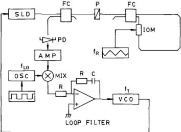
3. Experimental set-up
A schematic diagram of our experimental set-up is shown in figure 1 . Nominally 3 dB fibre couplers are used . The gyroscope was formed using a polarization-maintaining fibre coil 12 cm in diameter . A commercial integrated-optic E-O phase modulator, produced by Crystal Technology Co ., was used as the phase modulator in the FOG . This device is fabricated using LiNbO3 with a fibre-pigtailed output,
V„ = 3 V,
f
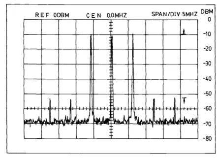
3 dB> 3 GHz . In our system, the V„of the device will limit the maximum multiple number ; thus a smaller V„ will be more suitable for this design . A superluminescent laser diode source of wavelength .=0 .83 gm with fibre-pigtailed output (Laser Diode Co .) was adopted as the light source . The temperature and driving current of the laser diode were stabilized to AT,< l . 0 x 10 -3 °C and Ai 51 . 0 gA respectively . Thus Iowas stabilized to DIo/Io<I .0 x 10 -4 .Two experiments were carried out using this experimental set-up . In the first experiment, a triangular waveform of frequency at 1 . 0 MHz with TS= 2i was applied to the integrated-optic (I-O) phase modulator . By adjusting the amplitude of the triangular waveform so that the corresponding phase deviation of the 1-0 phase modulator was equal to the integer number of n rad, then an optically purely sinusoidal waveform was generated . The output signal of the FOG was shown in figure 2 (a) for a phase deviation of 2x rad and figure 2 (b) for a phase deviation of 6x rad . The corresponding frequencies of 2 . 0 and 6 .0 MHz sinusoidal waveform were obtained . The spectrum of the 6 . 0 MHz beat signal is shown in figure 3 . A sideband suppression of 45 dB was observed .
FC P FC f R 177 LOOP FILTER N v v f T VCO IOM
Figure 1 . Experimental set-up of the optical signal generator and the optical-type electrical PLL system : SLD, superluminescent laser diode ; OSC, oscillator; MIX, mixer ; PD, photodetector ; AMP, amplifier; R, resistor ; C, capacitor ; FC, fibre coupler ; P, polarizer ; IOM, integrated-optic phase modulator ; VCO, voltage-controlled oscillator .
1120
Pie- Yau Chien and Ci-Ling Pan
(a)
(b)
Figure 2 . The waveform converter effect from the applied triangular waveform to sinusoidal
waveform : (a) multiplicative factor of 2 . 0 ; (b) multiplicative factor of 6 .0. The lower
trace is the applied triangular waveform . The upper trace is the output sinusoidal
waveform .
In the second experiment, we attempted to demonstrate the optical-type PLL
system . In this experiment, the 1 . 0 MHz triangular waveform was used as the
reference signal . To demonstrate the phase locking, a 6 . 0 MHz voltage-controlled
oscillator modulating the driving current of the laser diode was used as the target
oscillator . A 100 kHz oscillator was used as the offset local oscillator to mix the
output signal of the optical receiver of the FOG for frequency-tracking performance
testing . This was implemented by applying a 1 . 0 kHz square waveform to dither the
frequency of the 100 kHz signal . A loop filter of the proportional and integrating (PI)
type was used to implement the phase-tracking function of the PLL circuit . The
natural frequency of the servo system was selected to be 10 .0 kHz and the damping
factor was designed to be 1 .0 in the PI compensation circuit . Figure 4 illustrates the
frequency-tracjing performance of the PLL circuit when a 1 . 0 kHz dither signal was
applied to modulate the 100 kHz signal and the response of the PLL circuit at the
Optical signal generator
1121
Figure 3 . The output spectrum of the generated 6 . 0 MHz optical sinusoidal waveform.
QQa^v
i
2tE4ir"
Figure 4 . The tracking performance of the PLL system . The upper trace is the dither signal . The lower trace is the signal at the input of the voltage-controlled oscillator .
j dee =50x10 rad
T
10min
Figure 5 . The phase error Beof the PLL system under the condition that the phase was
locked . REF ODBM C E N 0.0MHZ SPAN/DIV 5MHZ DBM 0 -10 -20 -30 -40 -50 E
~
i ~ -60r,
0
mm
N1.~
d ~ .~ 1 .a ~r 111 .E -70 -801122
Optical signal generator
output of the loop filter . An excellent tracking-capability was achieved . The tracking time was about 0.1 ms . The target oscillator was thus locked at 6.0±0.1 MHz . The
phase error of the PLL circuit at the input of the loop filter was stabilized to LB e < 2.0 x 10-°rad with a measurement bandwidth of 10.0 Hz .
4. Conclusions
In summary, we have demonstrated a novel optical signal generator with a frequency-multiplied output . This was accomplished by using a triangularly phase-modulated FOG in the static state . The multiplicative factor was limited by the maximum phase deviation allowed in the 1-0 phase modulator . The sideband suppression is limited by the linearity of slope of the triangular waveform and its amplitude stability . It can be improved by employing a stabilized current source to charge a precision capacitor and an amplitude-stabilized circuit respectively .
An interferometric phase locking of two electronic oscillators at 1 .0 and 6.0 MHz with an intensity-modulated laser diode and a static phase-modulated FOG has also been demonstrated . The tracking time was about 0.1 ms and the phase error was less than 6.0 x 10⁻⁵rad Hz-1 /2 . This novel optical-type PLL design can in principle be extended to the gigahertz region and beyond .
Acknowledgments
This work was partially supported by the National Science Council of the Republic of China under Grant No . NSC-80-0417-E-009-05 .
References
[1] GARDNER, F . M ., 1979,Phaselock Technique (New York : Wiley) .
[2] MAEDA, M . W ., and KAZOVSKY, L . G ., 1989, IEEE Photon . Technol. Lett ., 1, 455 .
[3] KAZOVSKY, L . G ., andJENSEN, B ., 1990,IEEE Photon . Technol . Lett ., 2,526 . [4] EICHEN, E ., and SILLETI, A ., 1987, IEEE J . Lightwave Technol., LT-5, 1377 . [5] HEMERY, E ., CHUSSEAU, L.,and LouRTioz, J . M ., 1989, Electron . Lett., 25, 42 . [6] WANG, J ., KRUGER, U ., SCHWARZ, B .,andPERTERMANN, K ., 1989,Electron . Lett ., 25,722 . [7] PAVLATH, G . A .,and SHAW, H . J ., 1982,Appl . Optics, 21, 1752 .
[8] BERGH, R . A ., LEFEVRE, H . C ., and SHAW, H . J ., 1981, Optics Lett ., 6, 502 .