國 立 交 通 大 學
機 械 工 程 學 系
碩 士 論 文
垂直圓柱容器中空氣經由多孔板衝擊至一加熱圓盤之
混合對流渦流結構之研究
Experimental Study of Mixed Convective Vortex Flow
in an Air Flow Moving through a Showerhead and
Impinging onto a Heated Disk in a Vertical
Cylindrical Chamber
研 究 生 : 汪 書 磊
指 導 老 師: 林 清 發 博 士
垂直圓柱容器中空氣經由多孔板衝擊至一加熱圓盤之混和
對流渦流結構之研究
Experimental Study of Mixed Convective Vortex Flow in an Air Flow
Moving through a showerhead and Impinging onto a Heated Disk in
a Vertical Cylindrical Chamber
研 究 生:汪 書 磊 Student:Shu-Lei Wang
指導教授:林 清 發 Advisor:Tsing-Fa Lin
國立交通大學
機械工程學系
碩士論文
A Thesis
Submitted to Department of Mechanical Engineering
Collage of Engineering
National Chiao Tung University
In Partial Fulfillment of the Requirements
For the degree of
Master of Science
In
Mechanical Engineering
June 2009
Hsinchu, Taiwan, Republic of China
中 華 民 國 九 十 八 年 六 月
誌 謝
時光飛逝,回首在新竹這兩年來的點點滴滴,交大這充滿學術氣息的環境下 似乎讓我在知識上成長茁壯許多。本論文之所以可以順利完成,首先要感謝的是 指導老師 林清發教授嚴謹及殷切的指導,使學生能培養出獨立思考、釐清並自 行解決問題的能力;更在學生撰寫論文時,不辭辛勞逐字斧正文稿,在此獻上最 高謝意。在研究所期間,要特別感謝張文瑞、謝汎鈞及廖永明學長在實驗設備設 計、架設上的協助指導,並且在生活及課業上給予建議,使我受益匪淺,謝謝您 們。 文慶、譯徵這群不只是求學中的同學,更是生活上的好朋友。研究所之所以能 在緊湊忙碌又充滿歡樂中的氣氛中度過,即是靠這些同學兼好友的夥伴們相互協 助幫忙,令我永生難忘。另外也要感謝 建安、象麟、宏嘉、書豪、俊州等一群 努力的學長學弟幫忙及合作,希望你們能繼續保持實驗室優良傳統,並帶著實驗 室進步。 最後更要感謝父母及家人對於我無怨無悔付出及支持,使我可以無後顧之憂 的專注於研究,並且可無憂無慮過求學生活。並特別要感謝室友瑞毅、好友古必、 佳芳、邱哥、蘇哥、蛙王、老王、穎志、阿軒、阿棒、文錚、胖子、陳老師、長 青的陪伴,生活最精采的部分是你們陪我渡過,不管在課業上或生活上的關心與 支持使我有勇氣面對一切的困難挑戰。能與你們相處是我這輩子最大的幸福。 最後,僅以本文獻給我所關心的人和所有關心我的人。 書磊 謹致 2009/6/27 于風城交大垂直圓柱容器中空氣經由多孔板衝擊至一加熱圓盤
之混合對流渦流結構之研究
研究生:汪 書 磊 指導老師:林 清 發 博士 國立交通大學 機械工程學系 摘 要 本篇論文利用實驗流場觀測方法探討在垂直圓柱容器中空氣經由多孔板衝 擊至一加熱圓盤穩態及非穏態渦流結構之流場特性進行研究。主要的目的是藉由 多孔氣流的效應來降低在圓柱中因慣性力所造成的渦流結構,並闡釋多孔板放入 入口處所造成的效應對於穩態及暫態過程中熱浮力驅動之渦流結構之影響以及 探討慣性力渦流結構出現的機制。另外,熱浮力所造成的不穩定現象也一併討論 說明。本實驗研究之操作範圍分別是:噴流至圓盤的距離20~40 mm,多孔板的 直徑固定為76.2 mm,流量變化 0~5.0 slpm,加熱圓盤與入口冷空氣間的溫度差 範圍0~25.0℃,整體的噴流雷諾數變化為 0~89,所相對的噴流雷諾數變化為 0 ~28,相對於雷利數 0~150,325。 從流場可視化可以很清楚地發現慣性力所造成的第一類和第二類渦流結構 均有被抑制並且出現的機制也延後發生,原因是多孔板所造成的效果。當∆T ≠ 0 時,慣性力所造成的第二類渦流並無出現且熱浮力所驅動的渦流結構會一直存在 流場中。另外,針對不同高度(H = 20.0, 30.0 及 40.0mm)我們分別定義出四種型 態的流譜型態:(1) 理想流譜,(2) 熱浮力所主導的流譜,(3) 慣性力所主導的流 譜以及(4) 慣性力和熱浮力共同主導的流譜,並且界定不穩定的流場型態以及出 現的範圍。其中,理想流譜僅出現在完全沒有加熱的情況且低流量。除此之外,本研究還比較有和沒有加裝多孔板對於流場型態有多大的影響。 從相關的流場圖分析結果得知,加裝多孔板確實能夠有效地抑制慣性力所產生的 渦流結構在圓柱型腔體內出現。最後,我們將流場轉變以及熱浮力造成不穩定性 的範圍以實驗結果做分析,求得經驗公式。
i
Experimental Study of Mixed Convective Vortex Flow in an Air Flow
Moving through a showerhead and Impinging onto a Heated Disk in
a Vertical Cylindrical Chamber
Student: Shu-Lei Wang Advisor: Prof. Tsing-Fa Lin Department of Mechanical Engineering
National Chiao Tung University
ABSTRACT
An experimental flow visualization is carried out in the present study to investigate how the installation of a showerhead at the jet injection nozzle affects the vortex flow resulting from multiple air jets impinging onto a heated horizontal circular disk confined in a vertical cylindrical chamber. The study is motivated by the fact that the multiple air jets of small cross section are less likely to induce inertia-driven vortex flow. Particular attention is paid to examining the effects of the showerhead installation on the characteristics of steady and time-dependent buoyancy-driven vortex flows. Besides, the onset of the inertia-driven vortex flow and the instability of the buoyancy-driven vortex flow will be inspected. In the present experiment three jet-disk separation distances are considered with H = 20.0, 30.0, and 40.0 mm for a fixed injection nozzle diameter (Dn = 76.2 mm). The jet flow rate is
varied from 0 to 5.0 slpm (standard liter per minute) for the overall jet Reynolds number Ren ranging from 0 to 89 and the jet Reynolds number Rej ranging from 0 to
ii
28. The temperature difference between the disk and the air injected into the chamber is varied from 0 to 25.0 for the Rayleigh number Ra ranging from 0 to ℃ 150,325.
The results from the flow visualization clearly show the significant effects of the showerhead on the critical Rej for the onset of the primary and secondary
inertia-driven rolls. Specifically, the onsets of the inertia-driven rolls are delayed to higher Rej through the installation of the showerhead. Besides, the secondary
inertia-driven roll does not appear in the chamber with ∆T ≠ 0 for HDn = 0.26 to 0.52.
Moreover, we identify four different types of vortex flow (plug flow, buoyancy-driven vortex flow, inertia-driven vortex flow, and mixed flow) and delineate temporal state of the flow when HDn is varied from 0.26 to 0.52. Flow regime maps are presented.
The plug flow only occurs at lower Rej for the disk unheated (Ra = 0). The buoyancy
roll always appears for HDn = 0.39 and 0.52 even at a small ∆T of 1℃. Besides, we
compared the vortex flows in the chamber with and without the showerhead installation. The result shows that the showerhead installation at the injection nozzle can effectively suppress the inertia-driven vortex rolls. Finally, empirical correlations are proposed for the boundaries separating the buoyancy-driven and mixed vortex flows and for the onset conditions of the vortex flow instabilities for HDn.
iii
TABLE OF CONTENTS
ABSTRACT i
TABLE OF CONTENTS
iii
LIST OF TABLES
v
LIST OF FIGURES
vi
NOMENCLATURE xi
CHAPTER 1 INTRODUCTION
1.1 Motivation 1.2 Literature Review1.3 Objective and Scope of Present Study
1
1
2
8
CHAPTER 2 EXPERIMENTAL APPARATUS AND
PROCEDURES
2.1 Experimental Apparatus 2.2 Experimental Procedures11
11
14
CHAPTER 3 DIMENSIONLESS GROUPS AND
UNCERTAINTY ANALYSIS
3.1 Dimensionless Groups 3.2 Uncertainty Analysis20
20
21
iv
CHAPTER 4 RESULTS AND ISCUSSION
4.1 Pure Buoyancy- and Inertia- Driven Vortex Flow Patterns
4.2 Typical Vortex Flow Patterns
4.3 Onset of Inertia-Driven Vortex Rolls
4.4 Effects of Parameters on Vortex Flow Characteristics 4.5 Flow Regime Maps
4.6 Comparison of Vortex Flows with and without Showerhead Installation
25
26
28
29
31
33
36
CHAPTER 5 CONCLUDING REMARKS AND
RECOMMENDATION FOR FUTURE WORK
5.1 Conclusion Remarks
5.2 Recommendations for Future Work
REFERENCES
118
118
120
121
v
LIST OF TABLES
Table 3.1 Summary of uncertainty analysis. 24
Table 4.1 Critical condition for the onset of the primary and secondary inertia-driven vortex rolls for H = 20-40 mm with disk unheated (Ra = 0)
37
Table 4.2 Critical condition for the onset of the primary inertia-driven vortex roll for H = 20-40 mm with heated disk
38
Table 4.3 Critical condition for the onset of the primary and secondary inertia-driven vortex roll without showerhead for H = 20-40 mm with unheated disk (Ra = 0)
vi
LIST OF FIGURES
Fig. 1.1 Schematic of the flow patterns in a confined impinging jet depicting the plug-flow, buoyancy-induced flow, and rotation-induced flow.
9
Fig. 1.2 Flow regimes associated with a circular jet impinging onto a flat plate.
10
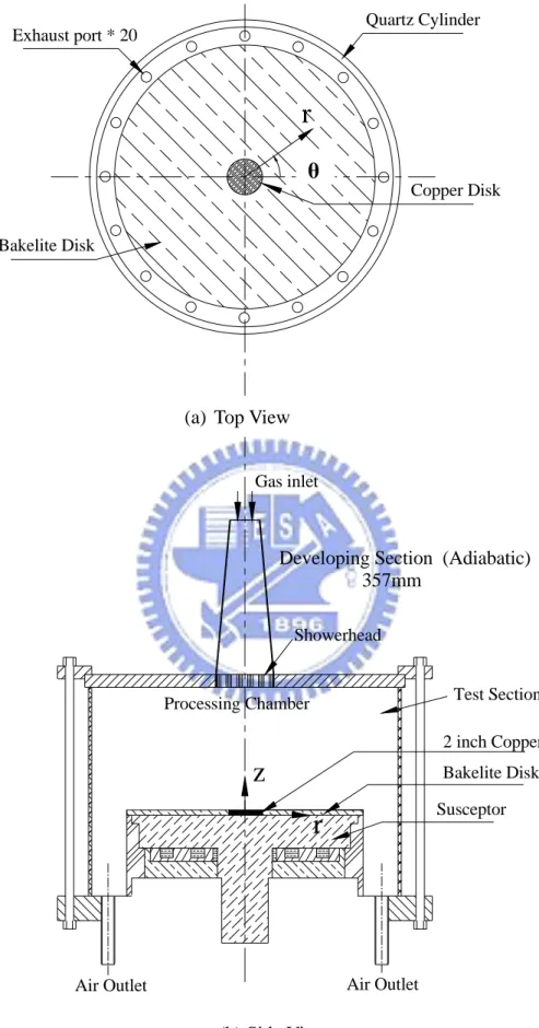
Fig. 2.1 Schematic diagram of the experimental apparatus. 15 Fig. 2.2 Schematic diagram of the processing chamber from top view and
side view.
16
Fig. 2.3 Schematic diagram of the showerhead. 17
Fig. 2.4 Schematic diagram of heating unit. 18
Fig. 2.5 Schematic diagram of the locations of the detection points on the copper disk.
19
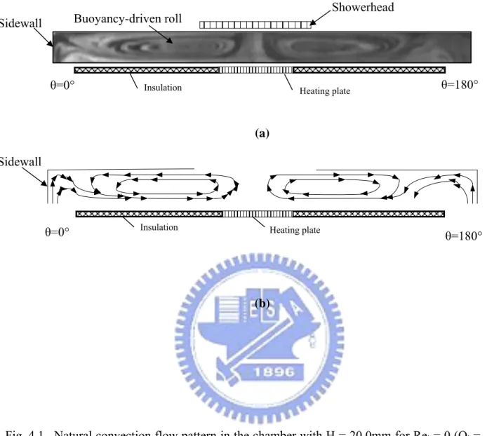
Fig. 4.1 Natural convection flow pattern in the chamber with H = 20.0mm for Rej = 0 (Qj = 0 slpm) and Ra = 18,790 (ΔT = 25 ) for (a) side ℃
view flow photo taken at the cross plane θ=0° & 180° and (b) the corresponding schematically sketched cross plane vortex flow.
41
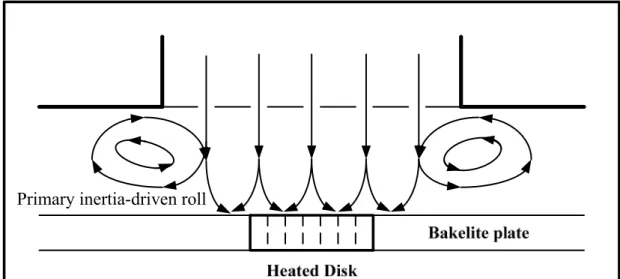
Fig. 4.2 Inertia driven flow pattern in the chamber with H = 30.0mm for Ren
= 89, Rej = 28 (Qj = 5.0 slpm) and Ra = 0 (ΔT = 0℃) for (a) side
view flow photo taken at the cross plane θ=0° & 180° and (b) the corresponding schematically sketched cross plane vortex flow.
42
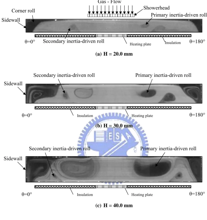
Fig. 4.3 Side view flow photos taken at the cross plane θ=0° & 180° at Rej =
14 (Qj = 2.0 slpm, Ren = 35) and ΔT=0℃ (Ra=0) for (a) H = 20.0
mm, (b) H = 30.0 mm and (b) H = 40.0 mm.
43
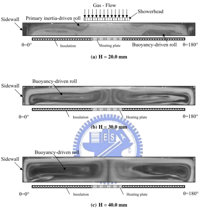
Fig. 4.4 Side view flow photos taken at the cross plane θ=0° & 180° at Rej =
22 (Qj = 4.0 slpm, Ren = 71) and ΔT = 0℃ (Ra = 0) for (a) H = 20.0
mm, (b) H = 30.0 mm and (b) H = 40.0 mm.
44
Fig. 4.5 Side view flow photos taken at the cross plane θ = 0° & 180° at Rej
= 11 (Qj = 2.0 slpm, Ren= 35), and ΔT=10℃ for (a) H = 20.0 mm
(Ra = 7,516), (b) H = 30.0 mm (Ra = 25,367), and (c) H = 40.0 mm (Ra = 60,130).
45
Fig. 4.6 Side view flow photos taken at the cross plane θ = 0° & 180° at Rej
= 28 (Qj = 5.0 slpm, Ren = 89), and ΔT = 10℃ for (a) H = 20.0 mm
(Ra = 7,516), (b) H = 30.0 mm (Ra = 25,367), and (c) H = 40.0 mm (Ra = 60,130).
vii
Fig. 4.7 Sketched the streamline through the showerhead installation and impinging onto the heated disk.
47
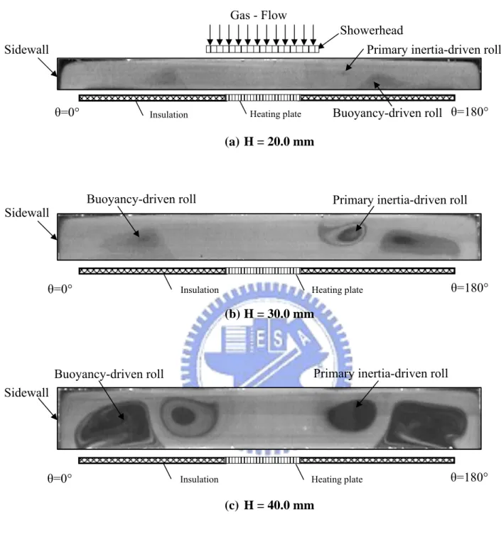
Fig. 4.8 Side view flow photos taken at the cross plane θ = 0° & 180° at Rej
= 28 (Qj = 5.0 slpm, Ren = 89), and ΔT = 0℃ for (a) H = 20.0 mm,
(b) H = 30.0 mm, and (c) H = 40.0 mm.
48
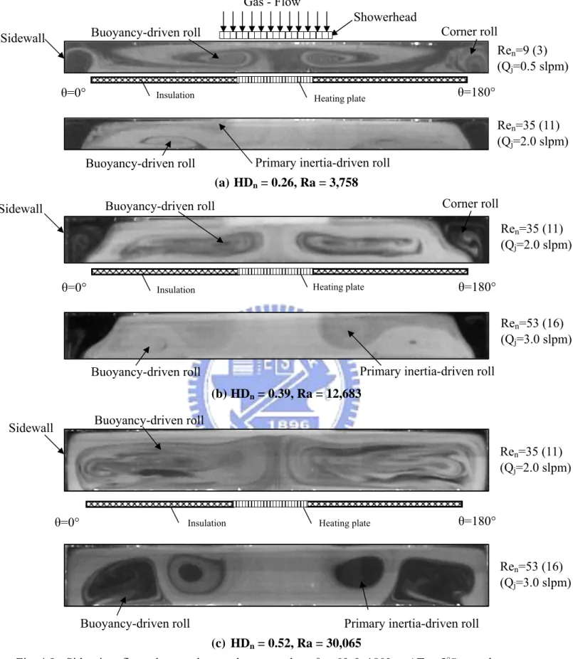
Fig. 4.9 Side view flow photos taken at the cross plane θ = 0° & 180° at ΔT = 5℃ steady state for various Qj (a) HDn = 0.26, Ra = 3,758, (b)
HDn = 0.39, Ra = 12,683 and (c) HDn = 0.52, Ra = 30,065.
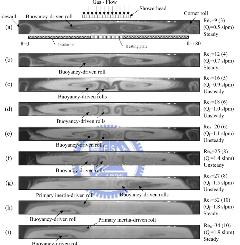
49
Fig. 4.10 Side view flow photos taken at the cross plane θ = 0° & 180° for various jet Reynolds numbers at Ra = 3,758 (ΔT = 5℃) and H = 20.0 mm for Ren = (a) 9, (b) 12, (c) 16, (d) 18, (e) 20, (f) 25, (g) 27,
(h) 32, (i) 34, (j) 35, (k) 44, (l) 53, (m) 71 and (n) 89.
50
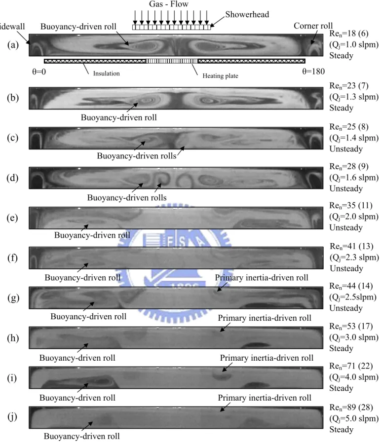
Fig. 4.11 Side view flow photos taken at the cross plane θ = 0° & 180° for various jet Reynolds numbers at Ra = 7,516 (ΔT = 10℃) and H = 20.0 mm for Ren = (a) 18, (b) 23, (c) 25, (d) 28, (e) 35, (f) 41, (g)
44, (h) 53, (i) 71 and (j) 89.
52
Fig. 4.12 Side view flow photos taken at the cross plane θ = 0° & 180° for various jet Reynolds numbers at Ra = 11,274 (ΔT = 15℃) and H = 20.0 mm for Ren = (a) 18, (b) 27, (c) 28, (d) 30, (e) 34, (f) 35, (g)
44, (h) 53, (i) 57, (j) 59, (k) 62, (l) 71 and (m) 89.
53
Fig. 4.13 Side view flow photos taken at the cross plane θ = 0° & 180° for various jet Reynolds numbers at Ra = 15,032 (ΔT = 20℃) and H = 20.0 mm for Ren = (a) 18, (b) 27, (c) 30, (d) 34, (e) 35, (f) 37, (g)
44, (h) 53, (i) 57, (j) 62, (k) 71 and (l) 89.
55
Fig. 4.14 Side view flow photos taken at the cross plane θ = 0° & 180° for various jet Reynolds numbers at Ra = 18,790 (ΔT = 25℃) and H = 20.0 mm for Ren = (a) 18, (b) 27, (c) 35, (d) 37, (e) 39, (f) 41, (g)
44, (h) 53, (i) 60, (j) 62, (k) 64, (l) 71, (m) 80 and (n) 89.
57
Fig. 4.15 Side view flow photos taken at the cross plane θ = 0° & 180° for various jet Reynolds numbers at Ra = 2,536 (ΔT = 1℃) and H = 30.0 mm for Ren = (a) 27, (b) 30, (c) 35, (d) 37, (e) 39, (f) 44, (g)
53, (h) 71 and (i) 89.
59
Fig. 4.16 Side view flow photos taken at the cross plane θ = 0° & 180° for various jet Reynolds numbers at Ra = 5073 (ΔT = 2℃) and H = 30.0 mm for Ren = (a) 18, (b) 34, (c) 35, (d) 37, (e) 39, (f) 44, (g)
53, (h) 71 and (i) 89.
viii
Fig. 4.17 Side view flow photos taken at the cross plane θ = 0° & 180° for various jet Reynolds numbers at Ra = 7,610 (ΔT = 3℃) and H = 30.0 mm for Rej = (a) 35, (b) 37, (c) 39, (d) 41, (e) 43, (f) 44, (g) 53,
(h) 71 and (i) 89.
63
Fig. 4.18 Side view flow photos taken at the cross plane θ = 0° & 180° for various jet Reynolds numbers at Ra = 10,146 (ΔT = 4℃) and H = 30.0 mm for Ren = (a) 18, (b) 35, (c) 39, (d) 43, (e) 44, (f) 46, (g)
48, (h) 50, (i) 53, (j) 71 and (k) 89.
65
Fig. 4.19 Side view flow photos taken at the cross plane θ = 0° & 180° for various jet Reynolds numbers at Ra = 12,683 (ΔT = 5℃) and H = 30.0 mm for Ren = (a) 18, (b) 35, (c) 41, (d) 44, (e) 48, (f) 53, (g)
62, (h) 71 and (i) 89.
67
Fig. 4.20 Side view flow photos taken at the cross plane θ = 0° & 180° for various jet Reynolds numbers at Ra = 17,757 (ΔT = 7℃) and H = 30.0 mm for Ren = (a) 18, (b) 35, (c) 43, (d) 44, (e) 46, (f) 48, (g)
50, (h) 53, (i) 62, (j) 71, (k) 80 and (l) 89.
69
Fig. 4.21 Side view flow photos taken at the cross plane θ = 0° & 180° for various jet Reynolds numbers at Ra = 25,367 (ΔT = 10℃) and H = 30.0 mm for Ren = (a) 18, (b) 35, (c) 44, (d) 46, (e) 53, (f) 71, and
(g) 89.
71
Fig. 4.22 Side view flow photos taken at the cross plane θ = 0° & 180° for various jet Reynolds numbers at Ra = 38051 (ΔT = 15 ) and H = ℃ 30.0 mm for Ren = (a) 18, (b) 35, (c) 48, (d) 50, (e) 53, (f) 62, (g)
71, and (h) 89.
72
Fig. 4.23 Side view flow photos taken at the cross plane θ = 0° & 180° for various jet Reynolds numbers at Ra = 50,734 (ΔT = 20 ) and H = ℃ 30.0 mm for Ren = (a) 18, (b) 35, (c) 51, (d) 53, (e) 71, (f) 73, (g)
80, and (h) 98.
74
Fig. 4.24 Side view flow photos taken at the cross plane θ = 0° & 180° for various jet Reynolds numbers at Ra = 63,418 (ΔT = 25 ) and H = ℃ 30.0 mm for Ren = (a) 18, (b) 35, (c) 53, (d) 57, (e) 59, (f) 71, (g)
78, and (h) 89.
76
Fig. 4.25 Side view flow photos taken at the cross plane θ = 0° & 180° for various jet Reynolds numbers at Ra = 6,013 (ΔT = 1℃) and H = 40.0 mm for Ren = (a) 18, (b) 30, (c) 35, (d) 39, (e) 41, (f) 44, (g)
46, (h) 50, (i) 53, (j) 74 and (k) 89.
ix
Fig. 4.26 Side view flow photos taken at the cross plane θ = 0° & 180° for various jet Reynolds numbers at Ra = 12,026 (ΔT = 2℃) and H = 40.0 mm for Ren = (a) 18, (b) 35, (c) 43, (d) 44, (e) 46, (f) 48, (g)
53, (h) 71 and (i) 89.
80
Fig. 4.27 Side view flow photos taken at the cross plane θ = 0° & 180° for various jet Reynolds numbers at Ra = 18,039 (ΔT = 3℃) and H = 40.0 mm for Ren = (a) 18, (b) 35, (c) 43, (d) 44, (e) 46, (f) 48, (g)
50, (h) 53, (i) 71 and (j) 89.
82
Fig. 4.28 Side view flow photos taken at the cross plane θ = 0° & 180° for various jet Reynolds numbers at Ra = 24,052 (ΔT = 4℃) and H = 40.0 mm for Ren = (a) 18, (b) 35, (c) 43, (d) 44, (e) 46, (f) 48, (g)
51, (h) 53, (i) 71 and (j) 89.
84
Fig. 4.29 Side view flow photos taken at the cross plane θ = 0° & 180° for various jet Reynolds numbers at Ra = 30,065 (ΔT = 5℃) and H = 40.0 mm for Ren = (a) 18, (b) 35, (c) 50, (d)51, (e) 53, (f) 55, (g) 57,
(h) 59, (i) 71 and (j) 89.
86
Fig. 4.30 Side view flow photos taken at the cross plane θ = 0° & 180° for various jet Reynolds numbers at Ra = 60,130 (ΔT = 10℃) and H = 40.0 mm for Rej = (a) 18, (b) 27, (c) 35, (d)44, (e) 53, (f) 55, (g) 57,
(h) 62, (i) 64, (j) 71, (k) 80, and (l) 89.
88
Fig. 4.31 Side view flow photos taken at the cross plane θ = 0° & 180° for various jet Reynolds numbers at Ra = 90,195 (ΔT = 15℃) and H = 40.0 mm for Ren = (a) 18, (b) 35, (c) 44, (d)53, (e) 57, (f) 59, (g) 62,
(h) 71, (i) 80, and (j) 89.
90
Fig. 4.32 Side view flow photos taken at the cross plane θ = 0° & 180° for various jet Reynolds numbers at Ra = 120,260 (ΔT = 20℃) and H = 40.0 mm for Ren = (a) 18, (b) 35, (c) 53, (d)57, (e) 59, (f) 62, (g) 71,
(h) 80, (i) 87, and (j) 89.
92
Fig. 4.33 Side view flow photos taken at the cross plane θ = 0° & 180° for various jet Reynolds numbers at Ra = 150,325 (ΔT = 25℃) and H = 40.0 mm for Ren = (a) 18, (b) 35, (c) 53, (d)59, (e) 60, (f) 62, (g) 71,
(h) 80, (i) 89, (j) 98, and (k) 106.
94
Fig. 4.34 Flow regime map delineating plug flow, buoyancy-induced vortex flow, inertia-driven vortex flow and mixed flow for H = 20.0mm.
96
Fig. 4.35 Flow regime map delineating plug flow, buoyancy-induced vortex flow, inertia-driven vortex flow and mixed flow for H = 30.0mm.
97
Fig. 4.36 Flow regime map delineating plug flow, buoyancy-induced vortex flow, inertia-driven vortex flow and mixed flow for H = 40.0mm.
x
Fig. 4.37 Flow regime map delineating the temporal state of the vortex flow for H = 20.0mm
.
99
Fig. 4.38 Flow regime map delineating the temporal state of the vortex flow for H = 30.0mm
.
100
Fig. 4.39 Flow regime map delineating the temporal state of the vortex flow for H = 40.0mm
.
101
Fig. 4.40 Non-periodic vortex flow for H = 20.0 mm and Ra= 3,758 (ΔT = 5℃) at Ren = 20 (Qj = 1.1 slpm, Rej = 6) illustrated by side view
flow photos taken at the cross plane θ= 0° & 180°.
102
Fig. 4.41 Time-periodic vortex flow for H = 30.0 mm and Ra = 25,367 (ΔT = 10 ) at Re℃ n = 46 (Qj = 2.6 slpm, Rej = 14) illustrated by side view
flow photos taken at the cross plane θ= 0° & 180° at selected time instants in a typical periodic cycle (tp = 8.0 sec).
104
Fig. 4.42 Time-periodic vortex flow for H = 40.0 mm and Ra = 120,260 (ΔT = 20℃) at Ren = 89 (Qj = 5.0 slpm, Rej = 28) illustrated by side view
flow photos taken at the cross plane θ = 0° & 180° at selected time instants in a typical periodic cycle (tp = 6.0 sec).
105
Fig. 4.43 Schematic illustration of the velocity distribution at the gas injection nozzle for the chamber without showerhead (a) and with showerhead (b).
106
Fig. 4.44 Side view flow photos taken at the cross plane θ = 0° & 180° for various Qj at ΔT = 0 (Ra = 0) and H = 20.0 mm.
107
Fig. 4.45 Side view flow photos taken at the cross plane θ = 0° & 180° for various Qj at ΔT = 0 (Ra = 0) and H = 30.0 mm.
108
Fig. 4.46 Side view flow photos taken at the cross plane θ = 0° & 180° for various Qj at ΔT = 0 (Ra = 0) and H = 40.0 mm.
109
Fig. 4.47 ide view flow photos taken at the cross plane θ = 0° & 180° for various ΔT at Qj = 2 slpm (Ren = 35, Rej = 11) and H = 20.0 mm.
110
Fig. 4.48 Side view flow photos taken at the cross plane θ = 0° & 180° for various ΔT at Qj = 4 slpm (Ren = 71, Rej = 22) and H = 20.0 mm.
111
Fig. 4.49 Side view flow photos taken at the cross plane θ = 0° & 180° for various ΔT at Qj = 2 slpm (Ren =35, Rej = 11) and H = 30.0 mm.
112
Fig. 4.50 Side view flow photos taken at the cross plane θ = 0° & 180° for various ΔT at Qj = 4 slpm (Ren = 71, Rej = 22) and H = 30.0 mm.
113
Fig. 4.51 Side view flow photos taken at the cross plane θ = 0° & 180° for various ΔT at Qj = 2 slpm (Ren = 35, Rej = 11) and H = 40.0 mm.
114
Fig. 4.52 Side view flow photos taken at the cross plane θ = 0° & 180° for various ΔT at Qj = 4 slpm (Ren = 71, Rej = 22) and H = 40.0 mm
NONMENCLATURE
Dj
Dn
Average diameter of holes in showerhead (mm) Diameter of jet at the large showerhead exit (mm) Dw Diameter of disk (mm)
Gr Grashof number, gβΔTH3 ν2 g Gravitational acceleration (m/s2) H Jet-to-disk separation distance (mm)
HDn Ratio of the jet-disk separation distance to the jet diameter, H/ Dn
N The number of the holes in the showerhead
Qj The total jet flow rate (Standard Liter per Minute, slpm)
z , ,
rθ Dimensional coordinates in cylindrical coordinate system Z
, ,
R Θ Dimensionless coordinates r R/ c, /360 , /θ ° z H
Ra Rayleigh number, gβΔTH αν3 Rc Radius of cylindrical chamber (mm)
Ren Overall jet Reynolds number, V ν
nDn
Rej Jet Reynolds number, V ν
jDj
Ta Ambient Temperature ( )℃
Th Temperature of the heated disk ( )℃
Tj Temperature of jet at the large showerhead exit ( )℃
t Time (sec)
Vn the average inlet speed of the air flow without the showerhead
installation (m/s)
Vj the average speed of the air jets at the holes in the showerhead (m/s)
Greek symbols
α Thermal diffusivity (m2/s)
β Thermal expansion coefficient (1/K)
ΔT Temperature difference between the heated disk and the air injected into the chamber ( )℃
ν Kinematic viscosity (m2/s)
ρ Density (kg/m3)
μ Dynamic viscosity (kg/ms) k Thermal conductivity (W/m
℃
)1
CHAPTER 1
IMTRODUCTION
1.1 Motivation of the study
Due to their superior heat transfer capability, impinging jets have been found in many technological applications such as heating, cooling, and drying of surfaces. For example, they are employed in paper and textile industries, electronics cooling of portable computers [1] and turbine blades, drying of veneer, thermal treatment of materials, etc. In steel or gas turbine industries impinging jets are often used to cool down the products after rolling. In some circumstances drying rate may be increased by an order of magnitude compared to contact drying. In laser or plasma cutting processes, the application of jet impingement cooling can reduce thermal deformation of products. Recently, impinging jets are widely employed in MOCVD (Metal Organic Chemical Vapor Deposition) growth of thin crystal films for solar cells [2].
It is well known that in the MOCVD processes the jet is no longer at a high speed. At low jet speed the buoyancy generated by the heated wafer can be relatively high compared with the jet inertia and the buoyancy driven flow recirculations tend to appear [3]. Particularly, the flow recirculations in MOCVD processing chamber have detrimental effects on the film properties. In order to obtain high quality solar cells, the flow in the growth processes of the thin films needs to be stable and does not contain any vortices. Thus the understanding and suppression of the inertia- and buoyancy-driven flow recirculations, which are normally in the form of vortex rolls, in the impinging jet flow are rather important in the thin crystal film growth. Apparently, these vortex structures in the MOCVD reactor are mainly affected by the jet inertia, the buoyancy force due to the heated wafer, and pressure gradient
2
associated with the disk rotation, along with the geometry of the chamber including the nozzle diameter, nozzle-to-wafer distance, wafer and chamber diameters. According to the prevailing flow patterns, Biber et al. [4] identified three distinct flow regimes in the vertical MOCVD processing chamber: (1) plug flow, where the gas flows smoothly over the substrate without any recirculation in the chamber, (2) buoyancy-induced flow, where the buoyancy force associated with the heated substrate induces upward flow and recirculation of the gas, and (3) rotation-induced flow, where a toroidal vortex forms near the chamber wall close to the upper disk surface (Fig. 1.1). Obviously, the plug flow is preferred in the growth of thin crystal film for solar cells in a vertical MOCVD reactor.
Attention is paid in the present study to exploring the possible vortex flow structures in a vertical MOCVD processing chamber. More specifically, the possible suppression of the vortex flow by placing a showerhead at the jet injection nozzle will be investigated.
1.2 Literature Review
Interest in exploring the characteristics of the flow and heat transfer associated with impinging jet applies to different kinds of domain in the past through experimental measurement and numerical simulation. Particularly, most of the studies focus on quantifying the highly efficient heat transfer associated with the high speed impinging jets impacted on the heated plate and the jets considered possess a much higher inertia force than the buoyancy force generated by the temperature nonuniformity in the flow. According to the flow characteristics of a free jet, McNaughton and Sinclair [5] proposed four main types of jet in their experimental
3
study and classified the jet by its Reynolds number Rej: (1) the dissipated-laminar jet
for Rej < 300, (2) fully laminar jet for 300 < Rej < 1000, (3) semi-turbulent jet for
1000 <Rej< 3000, and (4) fully turbulent jet for Rej > 3000. Moreover, the flow
structure of a jet impinging onto a surface can be subdivided into three characteristic regions according to Incropera [6] shown in Fig 1.2.: (1) the free jet region, (2) the impingement flow region, and (3) the wall jet region. In the free jet region, the shear-driven interaction of the exiting jet and ambient produces entrainment of mass, momentum, and energy. Near the injection nozzle the jet flow mainly moves in the axial direction and is not affected to a noticeable degree by the presence of the impingement surface. The impingement zone is characterized by a stagnation region and the turning of the jet to the radial direction, which affects transition of the wall jet further downstream. The wall jet region is in the downstream of the stagnation region but near the target plate in which the transverse velocity rises rapidly to a maximum near the wall and then falls at greater distance from the wall. More complete information on various aspects of the flow and heat transfer associated with the impinging jets can be found from the critical reviews by Polat et al. [7], Jambunathan et al. [8], and Viskanta [9].
In order to explore the detailed vortex flow structure, Behbahani et al. [10] visualized the coherent structure in an impinging circular air jet. Later Popiel and Trass [11] observed the detailed flow behavior of turbulent free and impinging round jets, showing the toroidal vortex initiation, vortex pairing, and fluid entrainment processes. They pointed out that the development of these large-scale vortex structures considerably enhanced the entrainment rate and mixing processes. Fitzgerald and Garimella [12] and Morris et al. [13 & 14] used numerical simulation and flow visualization to investigate the vortex flow characteristics for a liquid
4
impinging jet, which were found to be influenced by the jet Reynolds number Rej and
jet-disk separation distance H. The center of the inertia driven vortex roll was found to move away from jet axis at increasing Rej and H. Recently, the vortex flow
structures resulting from a low speed gas jet impinging onto a heated horizontal disk confined in a vertical cylindrical chamber at low Rej were visualized by Hsieh et al.
[15]. They showed that the gas flow recirculation was typically in the form of three circular vortex rolls including a primary vortex roll around the jet, a secondary vortex roll in the middle region and a buoyancy-induced vortex roll in the outer zone of the chamber. The inner and middle vortex rolls are respectively driven by the jet inertia and the viscous shear due to the nonuniform velocity distribution in the jet and are stronger and bigger at a high Rej. The secondary inertia-driven vortex roll only
appears at certain high Rej and is much smaller and weaker than the primary
inertia-driven vortex roll. The buoyancy driven outer vortex roll results from the temperature difference between the heated disk and inlet gas and is important at high buoyancy-to-inertia ratio. In addition to the appearance of vortices, the effects of the jet Reynolds number and jet-disk separation distance on the locations of the centers of the primary and secondary vortex rolls were investigated by Law and Masliyah [16]. Details on the size and locations of the inertia-driven primary and secondary vortex rolls affected by the jet Reynolds and Richardson numbers for a laminar confined slot-jet were examined by Sahoo and Sharif [17]. Moreover, the effects of the jet-disk separation distance on the vortex flow patterns were investigated by Hsieh and Lin [18] for HDj ≤ 3 where HDj = H/Dj. They reported the data for the size and onset of
the inertia- and buoyancy-driven vortex rolls affected by HDj. Moreover, the critical
condition for the onset of the inertia-driven time dependent flow for the unheated disk was also provided.
5
For a confined laminar slot impinging jet the critical jet Reynolds number for the onset of unsteady flow was numerically shown to be between 585 and 610 by Chiriac and Ortega [19]. Santen et al. [20 & 21] indicated that the onset of thermal instability became earlier at increasing buoyancy-to-inertia ratio. As the buoyancy-to-inertia ratio exceeds certain critical level, the buoyancy-driven secondary flow is so strong to cause the flow transition from a steady to an unsteady state. Chung and Luo [22] suggested that unsteady heat transfer at an impinging jet was strongly dependent on the vortex dynamics. Moreover, a laminar impinging jet with small pulsation at the outlet of the jet was numerically simulated by Poh et al. [23]. They showed that in a periodic cycle the large vortice appearing in the minimum velocity state was broken into two smaller vortices when the flow was accelerated sinusodially to arrive at the maximum velocity state, after which the two vortices merged again when the flow was decelerated back to the minimum velocity state. Hsieh et al. [24] and Law and Masliyah [25] found that the impinging jet flow structure was significantly influenced by the chamber geometry. Specifically, Hsieh et al.[24] revealed that inclining the chamber top could effectively suppress the buoyancy-induced vortex flow at low buoyancy-to-inertia ratios and the unsteady vortex flow oscillation could be completely stabilized even at high buoyancy-to-inertia ratios.
Heat transfer in the turbulent impinging jet was numerically predicted by Colucci and Viskanta [26], Gao and Ewing [27], and Narayanan et al. [28]. Colucci and Viskanta [26] reported the effects of a hyperbolic nozzle outlet on the local heat transfer. The numerical prediction from Gao and Ewing [27] revealed that the upper plate confinement did not exhibit noticeable effect on the heat transfer for the ratio of the jet-disk separation distance to the jet diameter greater than 1. Angioletti et al. [29] conducted an experiment to examine transitional unconfined impinging jets for 1,000
6
< Rej < 4,000. Their results showed that the local heat transfer was strongly
influenced by the impinging jet structures. Specifically, the maximum heat transfer coefficient offset was noted to result from the induced large-scale toroidal vortices on the plate. Furthermore, heat transfer in a confined impinging slot jet covering the laminar and turbulent regimes was studied by Park et al. [30]. Lin [31] provided the measured data for the heat transfer coefficient varied with the jet Reynolds number and the jet-disk separation distance in the laminar and transitional impinging jets.
Flow structure and heat transfer in an array of multiple impinging jets have received considerable attention in the past [32-37]. The interference between the adjacent jets and the upwash-fountain flow may become significant in certain ranges of the jet-jet spacing and jet-plate separation distance. Normally, these effects are small for a short jet-to-plate distance [32&37]. Besides, the convective heat transfer from the plate to the jet can be more uniform by a suitable choice of the parameters associated with the jet array.
Recently, chemical vapor deposition (CVD) has become the most widely used method to deposit thin crystal film. It have been known that the desirable features of the CVD processes include thickness uniformity, high deposition rate, control over the stoichiometry of the deposited material, and sharp interface. Thus flow in CVD chamber must be free from any vortex structure to avoid destroying the thin film uniformity. For this reason, it is important to suppress vortex flow in the CVD chamber. It is well known that in CVD processes the buoyancy-driven vortex flow can be suppressed by increasing the inlet flow rate, rotating the susceptor, reducing the chamber pressure and modifying the reactor shape. Hsieh [38] indicates that the centrifugal force of a rotating disk can reduce the bouyancy effect. Santen et al. [39 & 40] numerically examined the symmetry breaking of the flow owing to the
7
buoyancy effects in cold-wall stagnation flow CVD reactors and indicated that for the aspect ratio (height/diameter) of the reactor larger than one, stable non-axisymmetric flows could occur. Relatively high flow speed and/or rotation rate of the wafer were noted to be able to suppress the asymmetric flows. They also proposed that the symmetry-breaking of the flow can be suppressed by reducing the aspect ratio of the reactor. Soong et al. [41] presented the effects of gas flow, rotation of susceptor and natural convection on flow patterns in a model MOCVD reactor and found that the chaotic flow at a high buoyancy-to-inertia ratio could be stabilized by the susceptor rotation. They [42] further located the boundaries for the three flow regimes: buoyancy-, inertia- and rotation-dominated flows. Vanka and his colleagues [43-45] conducted a series of computational studies to explain the effects of the reactor pressure, substrate rotation rate, inlet flow rate, and reactor thermal boundary conditions on the flow in impinging jet CVD reactor. The buoyancy force is opposed by the inlet jet momentum and the force owing to substrate rotation. They were able to create a uniform mass transfer rate over the wafer. Fotiadis et al.[46 & 47] examined the effects of the operating parameters, reactor geometry, heat transfer characteristics on the flow patterns and deposition rate uniformity by using detailed transport models for vertical MOCVD reactors. They observed two types of recirculation cells in the vertical reactors: (1) natural convection cells driven by unstable density gradients due to large temperature gradients and (2) cells due to flow separation associated with sudden expansion in the flow cross-sectional area. The results demonstrated that natural convection effects could be reduced and thus the uniformity could be improved by increasing the inlet flow rate, rotating the susceptor, reducing the pressure, inverting the reactor, shortening the distance between inlet and susceptor, introducing baffles, and reshaping the reactor wall. To procure optimal
8
design of MOCVD reactor, Gadgil [48 & 49] installed a capillary plug inlet which not only removes the toroid, but acts as an ideal gas distributor and creates an axially umiform velocity profile. Phillips et al. [50] probed into effect of showerhead configuration on plasma enhanced chemical vapor deposition (PECVD) by three showerhead geometries: radial – the holes are arranged in a radial array, square – the pitches of the holes are all equal, and asymmetrical – the holes does not have regular arrangement. They found that the radial showerhead could provide the most homogeneous crystal film.
1.3 Objective and Scope of Present Study
The above literature review clearly reveals that some vortex rolls can be induced by the inertia and buoyancy forces in a mixed convective low speed gas jet impinging onto a heated wafer confined in a vertical MOCVD chamber. These vortex rolls become unsteady at high buoyancy-to-inertia ratios. The presence of these stable and unstable vortex rolls is detrimental to the thin film growth from MOCVD processes and is obviously unwelcome. In the present study we intend to explore the possible suppression of the inertia-driven vortex rolls by placing a showerhead at the gas injection nozzle to force the inlet gas flow to become multiple jets of small diameter and the inertia-driven vortex rolls are expected to have less chance to appear. Experimental flow visualization will be conducted to observe the vortex flow in a model processing chamber for growth of thin crystal film for solar cells for various jet flow rates, temperature differences between the wafer and inlet gas flow, and jet-disk separation distances. Attention will be focused on the vortex flow pattern affected by the installation of the showerhead.
Jet
△
T
Buoyancy-induced flowRotation-induced flow Plug-flow
Ω
Fig. 1.1 Schematic of the flow patterns in a confined impinging jet depicting the plug-flow, buoyancy-induced flow and rotation-induced flow.
10
Potential core
Free jet region
Wall jet region Stagnation region
Nozzle
H
Dj
11
CHAPTER 2
EXPERIMENTAL APPARATUS AND PROCEDURES
In order to conduct the experiment at reasonably low cost, we use air as the working fluid to replace the inert gases normally employed in real MOCVD processes. In view of the similar thermodynamic and thermophysical properties for various gases, the results obtained here are still applicable to the MOCVD systems. The experimental apparatus and procedures used in the present study to examine how the installation of a showerhead at the injection nozzle affects the characteristics of the mixed convective vortex flow resulting from a gas jet impinging onto a horizontal heated disk confined in a vertical cylindrical chamber are modified slightly from that established in our previous study [15].
2.1 Experimental Apparatus
A schematic of the experimental system is shown in Fig. 2.1. The test section includes a circular disk held horizontally in a vertical cylindrical chamber with the gas injected vertically downward through a showerhead into the chamber. Note that for clear illustration the plots in Fig. 2.1 are not directly proportional to the actual dimensions of the apparatus. The present experimental system consists of four major parts: (1) gas injection unit, (2) processing chamber, (3) heating unit, and (4) flow visualization unit. The major parts are briefly described in the following.
Processing chamber: The processing chamber schematically shown by the top
12
for the observation of the flow pattern in the chamber, is cylindrical and has a diameter of 291.0 mm. The distance between the chamber top and bottom is 200.0 mm. The chamber top is made of an 15-mm thick acrylic plate and the showerhead contains 490 circular holes all having the same diameter dj of 0.5 mm and a pitch of
3.0 mm (Fig. 2.3). These holes form concentric rings and the showerhead has a diameter of 3-inch. To facilitate the flow visualization, air is injected vertically downward through the showerhead into the cylindrical chamber and impinges directly onto the heated disk. The air flows first over the heated disk, then moves through the annular section of the chamber, and finally leaves the chamber via twenty circular outlets of 12.7 mm in diameter opened at the bottom of the chamber. The outside surface of the chamber is thermally well insulated to reduce the heat loss from the processing chamber during the experiment. More specifically, the entire chamber is insulated with a superlon insulator of 10.0-mm thick. The insulator can be opened during the flow visualization experiment.
Heating unit: The heating unit schematically shown in Fig. 2.4 is designed to
maintain the circular disk at the preset uniform temperature during the experiment. It is composed of 8-inch circular bakelite plate of 10.0-mm thick with a copper disk of 2-inch in diameter imbedded in its central portion. The copper disk is 11.0-mm thick and is placed on a thin heater of the same diameter which is heated by D.C. power supplies. The bakelite-copper plate and the heater are then placed on another bakelite disk. Note that the upper bakelite and copper disk surfaces must be at the exactly same horizontal level to avoid the wall jet flow to experience any step change between the surfaces. A proper control of the currents transferred from the power supplies to the heating coils leads to a nearly uniform copper disk temperature with a maximum deviation of 0.1℃ across the disk. The temperature of the copper disk at
13
selected detection points is measured by four T-type thermocouples inserted into the disk by the small holes drilled on the backside of the disk. The locations of the detection points in the disk are 1-mm below the upper surface of the disk and are indicated in Fig. 2.5.
Gas injection unit: The gas injection unit consists of a 2 HP air compressor, a
flow meter, a smoke generator, filters, a pressure regulator, connection pipes, a diffuser of 357-mm long, and a 3-inch showerhead. In the experiments, the air is drawn from the ambient by the compressor and sent into a 300-liter and 100-psi high-pressure air tank and is filtered to remove moisture and tiny particles. The installation of the high-pressure air tank intends to suppress the fluctuation of the air flow and to extend the life of the compressor. The gas flow rate from the air tank is controlled by the mass flow meter and then, the air is mixed with smoke tracers in the smoke generator. Before injected into the processing chamber, the gas moves vertically downward into the diffuser and crosses the showerhead which is coaxial with the processing chamber. Finally, the small-diameter multiple air jets from the showerhead impinges directly onto the horizontal heated copper disk. In the present study, the diffuser is thermally well insulated by a superlon insulation layer of 16.0-mm thick to prevent heat loss from the air flow. The distance between the lower surface of the showerhead and the upper surface of the heated disk is varied from 20.0 to 40.0 mm. The air temperature at the inlet of the diffuser is measured by a T-type thermocouple. The measured value is considered as the temperature of the air injected into the processing chamber in view of the good thermal insulation over the diffuser.
Visualization unit: A smoke-tracer flow visualization technique is employed to
14
cylindrical chamber. The smoke is produced from burning incense prepared from sandalwood. The smoke is mixed uniformly in the smoke generator and is carried out by the inlet air and is sent into the cylindrical chamber. The gas flow pattern in the chamber is illuminated by the vertical and horizontal plane light sheets produced by passing parallel lights from an overhead projector through adjustable knife edges. The experimental system is located in a darkroom to improve the contrast of the flow photos. The time variations of the flow pattern from the side views are recorded by the Sony digital video camera DCR-PC330.
2.2 Experimental Procedures
The experimental parameters included in the present study are the jet-disk separation distance, temperature difference between jet and disk, and jet flow rate. The temperature difference between jet and disk and jet flow rate are respectively varied from 0 to 25.0℃ and 0 to 5.0 slpm (standard liter per minute) for the jet-disk separation distance varying from 20.0 to 40.0 mm. The experiment starts with the air at the ambient temperature Ta compressed first into a smoke generator through the
showerhead, and then injected into the cylindrical chamber. The air then moves over the heated copper disk and finally leaves the processing chamber. Meanwhile the temperature of the disk and the air flow rate is controlled at the preset levels. The temporal changes of the flow patterns in the chamber are photographed from the side view by the Sony digital video camera DCR-PC330 for various jet-disk separation distances, gas flow rates, and temperature differences between the disk and inlet air.
A ir O utlet
A ir Inlet
Control Unit ( H eating Control U nit & D ata A cquisition S ysem)
2 91mm Test Se ction 1 2.7mm Air C ompressor Dryer W ater Filter W ater Filter Air Tank Flowmeter 0~20 slpm 0~ 1 slpm Particle Filter Oil F ilter B y pass P ressure R egulator Smoke Generator
Developing S ection (Adiabatic) 357mm T hermocouple T 20 ~ 4 0 m m C opper
R esista nce heatin g coil
H older
Sup erlo n (Insulator)
Tefllon (In su lato r)
z r
1 6mm 1 08mm
Pro cessin g Chamber
A ir O utlet Showerhead
Showerhead
2 inch Co pper
Fig. 2.1 Schematic diagram of the experimental apparatus.
15
Quartz Cylinder Exhaust port * 20
Copper Disk
Air Outlet
Test Section
Developing Section (Adiabatic) 357mm
z
Processing Chamber Air Outlet Showerhead 2 inch Copper Gas inletr
Bakelite Disk Bakelite Diskr
Susceptorθ
(a) Top View
(b) Side View
16
Fig. 2.2 Schematic diagram of the processing chamber from (a) top view and (b) side view.
Unit: mm
Fig. 2.3 Schematic diagram of the showerhead.
17
Copper Disk
Heater
Bakelite
Disk
R 25
.4
1
2
10
30
1
Unit: mm
Fig. 2.4 Schematic diagram of heating unit.
18
P2
P1
P3
P4
Fig. 2.5 Schematic diagram of the locations of the detection points
on the copper disk.
19
CHAPTER 3
DIMENSIONLESS GROUPS
AND UNCERTAINTY ANALYSIS
The dimensionless groups relevant to the present problem and the analysis of the uncertainties of the variables in this experiment are briefly examined in this chapter.
3.1 Dimensionless Groups
The non-dimensional parameters associated with the flow considered here are the ratio HDn of the jet-disk separation distance H to the diameter of the nozzle Dn,
overall jet Reynolds number Ren based on the average speed of the air flow Vn at the
injection nozzle and the diameter of the injection nozzle Dn, the jet Reynolds number
Rej based on the average speed of the air flow Vj leaving the holes in the showerhead
and the diameter of each hole dj, and the Rayleigh number Ra based on the
temperature difference between the heated disk and inlet gas ΔT and the jet-disk separation distance H. They are respectively defined as
H HD = D n n (3.1) 4 Re n n j n n Q V D D ν π ν = = (3.2) 4 Re j j j j j V d Q N d ν π ν = = (3.3) and (3.4) 20
where N is the number of the holes in the showerhead, α is the thermal diffusivity,
3 3 ( h j) gβ T T H gβ TH αν αν − Δ = = Ra
g is the gravitational acceleration, β is the thermal expansion coefficient, and is the kinematic viscosity.
ν
3.2 Uncertainty Analysis
An uncertainty analysis is carried out here to estimate the uncertainty levels in the experiment. Kline and McClintock [51] proposed a formula for evaluating the uncertainty in the result F as a function of independent variables,
, n 2 1,X , ,X X """" F=F
(
X1,X2,X3,"",Xn)
(3.5) The absolute uncertainty of F is expressed as2 1 2 n n 2 3 3 2 ⎥ ⎦ ⎤ 2 2 2 1 1 X X F X X F X X F X X F F ⎪⎭ ⎪ ⎬ ⎫ ⎪⎩ ⎪ ⎨ ⎧ ⎥ ⎦ ⎤ ⎢ ⎣ ⎡ δ ⎟⎟ ⎠ ⎞ ⎜⎜ ⎝ ⎛ ∂ ∂ + + ⎥ ⎦ ⎤ ⎢ ⎣ ⎡ δ ⎟⎟ ⎠ ⎞ ⎜⎜ ⎝ ⎛ ∂ ∂ + ⎢ ⎣ ⎡ δ ⎟⎟ ⎠ ⎞ ⎜⎜ ⎝ ⎛ ∂ ∂ + ⎥ ⎦ ⎤ ⎢ ⎣ ⎡ δ ⎟⎟ ⎠ ⎞ ⎜⎜ ⎝ ⎛ ∂ ∂ = δ " (3.6)
and the relative uncertainty of F is
2 1 2 n n n 2 2 2 2 X F ln 2 1 1 1 X X X ln F ln X X ln X X X ln F ln F F ⎪⎭ ⎪ ⎬ ⎫ ⎪⎩ ⎪ ⎨ ⎧ ⎥ ⎦ ⎤ ⎢ ⎣ ⎡ ⎟⎟ ⎠ ⎞ ⎜⎜ ⎝ ⎛ δ ⎟⎟ ⎠ ⎞ ⎜⎜ ⎝ ⎛ ∂ ∂ + + ⎥ ⎦ ⎤ ⎢ ⎣ ⎡ ⎟⎟ ⎠ ⎞ ⎜⎜ ⎝ ⎛ δ ⎟⎟ ⎠ ⎞ ⎜⎜ ⎝ ⎛ ∂ ∂ + ⎥ ⎦ ⎤ ⎢ ⎣ ⎡ ⎟⎟ ⎠ ⎞ ⎜⎜ ⎝ ⎛ δ ⎟⎟ ⎠ ⎞ ⎜⎜ ⎝ ⎛ ∂ ∂ = δ " (3.7)
If c... , then the relative uncertainty is 3 b 2 a 1X X X F= 2 1 2 3 3 ⎟⎟ ⎠ ⎞ 2 2 2 2 1 1 X X c X X b X X a F F ⎥ ⎥ ⎦ ⎤ ⎢ ⎢ ⎣ ⎡ + ⎜⎜ ⎝ ⎛ δ + ⎟⎟ ⎠ ⎞ ⎜⎜ ⎝ ⎛ δ + ⎟⎟ ⎠ ⎞ ⎜⎜ ⎝ ⎛ δ = δ "" (3.8)
where and are, respectively, the sensitivity coefficient and uncertainty level associated with the variable . The values of the uncertainty intervals are obtained by a root-mean-square combination of the precision uncertainty of the instruments and the unsteadiness uncertainty, as recommended by
) X / F (∂ ∂ i i X δ i X δ i X 21
Moffat [52]. The choice of the variable to be included in the calculation of the total uncertainty level of the result F depends on the purpose of the analysis. The uncertainties for the chosen parameters are calculated as follows:
i
X
(1) Uncertainty of the measured temperature difference Δ = − T Th Tj
1 2
2 2
(Th Tj) [( Th) ( Tj) ]
δ − = δ + δ (3.9)
(2) The dependence of the air properties k, µ, and ν on temperature (T in K) [46] is
) 118 T /( T 10 195 . 1 k= × −6 1.6 + ) 118 T /( T 10 448 . 1 × 6 1.5 + = μ − (3.10) ρ μ = ν /
The uncertainties of the properties are
T T T T T T T T T T T k k T k k δ ∂ ∂μ μ = μ δμ δ ∂ ∂ρ ρ = ρ δρ δ ∂ ∂ = δ (3.11)
(3) Uncertainty of the ratio HDn,
H HD = D n n (3.12) 1/2 2 2 δHD δH δD = + HD H D n n n n ⎡⎛ ⎞ ⎛ ⎞ ⎤ ⎢⎜ ⎟ ⎜ ⎟ ⎥ ⎝ ⎠ ⎢ ⎝ ⎠ ⎥ ⎣ ⎦ (3.13) 22
(4) Uncertainty of the Rayleigh number Ra, (3.14)
⎥⎦
⎤
⎢⎣
⎡
⎟ ⎠ ⎞ ⎜ ⎝ ⎛ ν δν + ⎟ ⎠ ⎞ ⎜ ⎝ ⎛ α δα + ⎟ ⎠ ⎞ ⎜ ⎝ ⎛ Δ Δ δ + ⎟ ⎠ ⎞ ⎜ ⎝ ⎛ δ + ⎟⎟ ⎠ ⎞ ⎜⎜ ⎝ ⎛ β β δ = δ 2 2 2 2 2 1/2 T T H H 3 g g Ra Ra (3.15) 3 3 ( h j) g T T H g TH Ra β β αν αν − Δ = =(5) Uncertainty of the overall jet Reynolds number Ren,
4 Re n n j n n Q V D D ν π ν = = (3.16) 1 / 2 2 2 2 Re Re j n n n j n Q D Q D δ δ δν δ ν ⎛ ⎞ ⎛ ⎞ ⎛ ⎞ = ⎜⎝ ⎟⎠ +⎜⎜ ⎟⎟ +⎜ ⎟ ⎝ ⎠ ⎝ ⎠
⎡
⎤
⎢
⎥
⎣
⎦
(3.17)(6) Uncertainty of the jet Reynolds number Rej,
4 Re j j j j j V d Q N d
ν
π ν
= = (3.18) 1 / 2 2 2 2 Re Re j j j j j j Q d Q d δ δν δ δ ν ⎛ ⎞ ⎛ ⎞ ⎛ ⎞ = ⎜ ⎟ +⎜ ⎟ +⎜ ⎟ ⎝ ⎠ ⎝ ⎠ ⎝ ⎠⎡
⎤
⎢
⎥
⎣
⎦
(3.19)The results from this uncertainty analysis are summarized in Table 3.1.
24
Parameter and Estimate Uncertainty
Parameters
Uncertainty
H (m)
± 0.00005 m
D
n± 0.000005 m
d
j± 0.0000005 m
T (℃)
± 0.2℃
ΔT (℃)
± 0.3℃
Q
j(slpm)
± 2%
μ (kg/ms)
ρ (kg/m
3)
υ (m
2/s)
± 0.05%
± 0.05%
± 0.07%
HD
n±
1.67%
Ra ±
8.6%
Re
n±
2.0%
Re
j±
2.0%
CHAPTER 4
RESULTS AND DISCUSSION
It is noted that the flow characteristics associated with the air jet impinging onto the heated disk confined in the cylindrical chamber under investigation are affected by the jet inertia, buoyancy force due to the heated disk, and jet-disk separation distance. In the present experiment the chamber is at the atmospheric pressure. Three jet-disk separation distances are considered with H = 20.0, 30.0, and 40.0 mm for the total jet flow rate Qj ranging from 0 to 5.0 slpm (standard liter per minute) and the
temperature difference between the disk and the air injected into the chamber ∆T is varied from 0 to 25.0℃. As noted in Chapter 3, the dimensionless groups governing the flow are the ratio of the jet-disk separation distance to diameter of the nozzle, jet Reynolds numbers and Rayleigh number. They have been respectively defined in Chapter 3 as HD = H D n n (4.1) 4 Re n n j n n Q V D D ν π ν = = (4.2) 4 Re j j j j j V d Q N d ν π ν = = (4.3) (4.4) 3 3 H gβ TH αν Δ = g (Th Tj) = Ra β αν −
The Grashof number is defined as 2 /Pr 3 Ra TH g Gr = Δ = ν β (4.5)
Thus the nondimensional jet-disk separation distance HDn ranges from 0.26 to 0.52,
25
26
the overall jet Reynolds number Ren from 0 to 89, the jet Reynolds number Rej from 0
to 28, the Rayleigh number Ra from 0 to 150,325, and the Grashof number Gr from 0 to 214,750. The inclusion of the two jet Reynolds numbers here intends to illustrate the effects of the showerhead on the resulting vortex flow in the chamber. In what follows selected flow photos taken from the side view are examined closely to delineate how the gas flow characteristics in the chamber with the showerhead installed at the gas injection nozzle are affected by the relevant parameters. Besides, the results for the cases with and without the showerhead installation are compared and discussed.
4.1 Pure Buoyancy- and Inertia- Driven Vortex Flow Patterns
At first, the vortex flow pattern in the chamber with the showerhead installation for the limiting case of no flow injection to the processing chamber at Qj = 0 in
examined. This is the pure natural convection flow. The typical steady natural convective vortex flow pattern observed in the cylindrical chamber with H = 20.0 mm, ∆T = 25℃ and Qj = 0 slpm (HDn = 0.26, Ra = 18,790, Ren = 0 and Rej = 0) at long
time when the flow already reaches steady state is illustrated in Fig. 4.1. The steady flow photo from the side view is shown here along with the corresponding schematically sketched vortex flow pattern to indicate the actual direction of the flow recirculation, which is based on the detailed flow visualization. The results manifest that there is a big buoyancy-driven circular roll in the processing chamber. A close inspection of the successive side view flow photos in the video tapes taken during the time evolution of the vortex flow reveals that the vortex roll almost fills the entire chamber and is nearly axisymmetric. Note that the buoyancy force pushes the gas to rise in the central portion of the chamber above the heated copper disk. As the gas flow encounters the chamber top, it moves radially outward along the top. Meanwhile,
27
the gas flow slows down and gets cooled during this outward moving. At some radial location it descends and later encounters the bakelite plate. The flow then moves radially inward forming a circular roll. We also note that this roll drags the air in the annular section of the chamber upward through viscous shearing effect, resulting a weak and small circular roll near the chamber side.
The typical vortex flow pattern in the cylindrical chamber with the showerhead installation for another limiting case of no buoyancy effect with H = 30.0 mm, ∆T = 0℃ and Qj = 5 slpm (HDn = 0.39, Ra = 0, Ren = 89 and Rej = 28) at long time when
the flow already reaches steady state is illustrated in Fig. 4.2. The steady flow photo from the side view is also shown here along with the corresponding schematically sketched vortex flow pattern to indicate the actual direction of the flow recirculation, which is based on the detailed flow visualization. This is the pure inertia-driven vortex flow. Note that there are two circular rolls in the processing chamber. A close inspection of the successive side view flow photos in the video tapes taken during the transient stage of the flow formation reveals that immediately after the impinging, the gas flow is deflected to move radially outward along the bakelite plate and slows down significantly due to the radial spread of the wall-jet flow. The wall-jet flow travels a certain distance from the stagnation point and then moves obliquely upwards since the wall jet momentum is unable to overcome the wall friction and the retarding effects of the entrained flow in the upper part of chamber. Then, the oblique flow is divided into two streams as it encounters the chamber top. One stream moves radially inwards towards the low pressure region created by the viscous shearing of the surrounding fluid associated with the jet injection, forming the inner roll which is therefore considered as the primary inertia-driven roll. Another stream is defected by the chamber top to move obliquely downwards along the edge of the bakelite disk, and finally leaves the chamber through the outlets in the chamber bottom. The outer
28
roll near the sidewall of the chamber is formed by the backflow from the outlets and rotates in the same direction as the primary inertia driven roll, which is called the corner roll. This corner roll becomes bigger and stronger for an increase in HDn as
shown for Fig. 4.3. It is noted that at a small jet Reynolds number the region above the copper disk is dominated by the plug flow. Furthermore, at high Qj a smaller third
roll which exists in the region between the primary inertia-driven roll and corner roll is found to be induced through the viscous shearing effects produced by the stronger and larger primary inertia-driven roll, which is termed as the secondary inertia-driven roll and has the opposite rotating direction with the primary inertia-driven roll. Both the primary inertia-driven roll and secondary inertia-driven roll become stronger and larger at increasing flow rate and jet-disk separation distance which can be seen from the flow photos in Fig. 4.4. The primary roll is known to result from the flow separation at the sudden expansion in the cross-sectional area as the jet flow enters the chamber, as already pointed out by Fotiadis et al. [46&47].
4.2 Typical Vortex Flow Patterns
Next, when there is a temperature difference between the jet and copper disk the typical steady vortex flow in the processing chamber with the showerhead installation shown in Fig. 4.5 for H = 20.0-40.0 mm, ∆T = 10.0℃ and Qj = 2.0 slpm
(HDn = 0.26-0.52, Rej = 11, Ra = 7,516-60,130, and Gr / Rej2 = 62.11-496.94) is
somewhat different from that in Fig. 4.3 for ∆T = 0℃. Note that when ∆T is raised to 10.0℃ the downward multiple-jet flow issuing from the showerhead is deflected to move radially outward at certain upper location by the vertically upward buoyancy generated by the heated disk and no corner roll is induced when the radial flow hits the chamber side. But, the photo in Fig. 4.5(a) reveals that a weak buoyancy-driven roll has been pushed far away from the heated disk by the strong jet flow. For larger
29
HDn of 0.39 and 0.52 (Figs. 4.5(b)&(c)) a big and strong buoyancy-driven circular
roll, however, appears since the Rayleigh number is proportional to H3. In fact the flow in the chamber is dominated by the buoyancy-driven roll at these larger HDn.
Again no inertia-driven vortex roll exists due to the large buoyancy-to-inertia ratio. Thus, we move further to examine the flow pattern for a higher gas flow rate of 5.0 slpm in Fig. 4.6. The steady flow photos from the side view show that the buoyancy-driven roll is pushed outward by the stronger jet flow when Qj is increased
to 5.0 slpm and it becomes smaller and weaker. Besides, a primary inertia-driven roll appears in the region near the edge of the showerhead (Fig. 4.6(a)). The appearance of this roll is attributed to the high speed gas flow experiencing a sudden expansion of the flow cross section at the exit of the jet injection nozzle as the flow enters the chamber. This roll is bigger and stronger for a large HDn (Figs. 4.6(b)&(c)).
Moreover, it should be noted that at increasing HDn both the primary inertia-driven
roll and buoyancy-driven roll are larger and contact with each other. These results are similar to that observed by Fotiadis et al. [46&47].
4.3 Onset of Inertia-Driven Vortex Flow
The understanding of the critical condition for the appearance of the inertia-driven vortex roll in the chamber is of fundamental interest in the fluid flow study and is valuable in vertical MOCVD thin film growth with the showerhead installation. Here, we move further to investigate the onset of inertia-driven vortex roll by visualizing the flow in the processing chamber at lower jet Reynolds number for the copper disk unheated (Ra = 0). The present data are summarized in Table 4.1 for the onset of the primary and secondary inertia-driven vortex rolls at HDn =
0.26-0.52. The trend is different from the previous study by Hsieh and Lin [18], which did not install the showerhead. Note that with the showerhead installation the onset of
30
the primary roll is delayed to a higher Rej. This can be attributed to some unique
features of the multiple small-diameter impinging jets resulting from the installation of the showerhead. As the present small-diameter jets with short pitches impinge the heated copper disk, the wall-jet flow streams from the adjacent impinging jets tend to offset each other and no vortice is induced, as schematically illustrated in Fig. 4.7. Obviously, the peripheral jets issuing from the holes closest to the showerhead edge can induce circular rolls which are apparently much weaker than that driven by the jet without the showerhead installation. Hence, the critical jet Reynolds number increases significantly by installing the showerhead. From the Table 4.1, at low average jet Reynolds number (Rej < 8.7) the plug flow dominates and only a corner roll appears
near the sidewall. But, a small increase in Qj causes the primary inertia-driven roll to
emerge from the edge of the showerhead. Moreover, the onset of the primary inertia-driven roll is delayed for an increase in HDn. The data in Table 4.1 also
manifest that the critical jet Reynolds number for the onset of secondary inertia-driven roll is nonmonotonic. This can be ascribed to the fact that at the small HDn of 0.26 the
chamber does not have enough space for the secondary inertia-driven roll to emerge. Thus a higher Rej is needed for the onset of the secondary roll. On the other hand, at
the high HDn of 0.52 the primary inertia-driven and corner rolls are relatively large
(Fig. 4.8(c)) and the space left in the chamber for the appearance of the secondary roll is again very limited. Hence a high Rej is also needed for the roll onset. As a result, at
the intermediate HDn of 0.39 the critical Rej for the onset of the secondary roll is
lowest.
Next, when there is a temperature difference between the jet and disk, the large buoyancy-driven roll is suppressed and a primary inertia-driven roll appears near the edge of the showerhead as the jet flow rate Qj is increased to a certain value so that
4.9 for various Qj and HDn at ∆T = 5℃. The critical values for the onset of the
inertia-driven roll for various ∆T are summarized in Table 4.2. The results show that for HDn = 0.26-0.52, the critical Rej for the onset of the primary roll is higher for a
higher ∆T, indicating that the flow inertia needs to be stronger to overcome the stronger buoyancy roll for the primary inertia driven vortex roll to appear. Besides, the critical buoyancy-to-inertia ratio increases substantially with Ra and HDn.
Furthermore, we found in the experiment that when the HDn is raised to 0.39 and 0.52,
the observed flow pattern reveals that for ΔT ≧ 1.0℃ the buoyancy-driven vortex roll always exists in the chamber even at the highest Qj of 5.0 slpm tested here. Finally,
there is no room available for the appearance of the secondary inertia-driven roll when the inertia and buoyancy rolls grow to a certain finite size and contact each other.
4.4 Effects of Parameters on Vortex Flow Characteristics
31
How the experimental parameters affect the gas flow pattern at long time in the processing chamber with the installation of the showerhead is demonstrated in Figs. 4.10-4.33 for HDn = 0.26-0.52 by presenting the long time side view flow photos taken at the cross plane θ = °0 &180 for various Rej and Ra. At first, the results
from Figs. 4.10-4.14 for HDn = 0.26 show that at low Reja large circular roll is driven
by the buoyancy (Figs. 10(a)&(b), 11(a)&(b), 12(a)-(c), 13(a)-(e), 14(a)-(e)). For a small increase in the jet Reynolds number this buoyancy roll is pushed outward by the jet inertia. Meanwhile, another small circular roll is induced right above the copper disk also by the buoyancy (Figs. 10(c)&(d), 11(d), 12(f), 13(f)&(g), 14(d)&(e)). The two buoyancy rolls decay noticeably for a further increase in Rej. At a certain high Rej
the inner buoyancy roll disappears and the outer buoyancy roll becomes small and weak. However, at this high Rej the primary inertia-driven appears. The primary roll