國 立 交 通 大 學
電信工程研究所
碩 士 論 文
多蜂巢多點協同下行傳輸網路下基於訊號
干擾雜音比限制之強韌性自動重傳放大後
中繼傳送設計
Robust CoMP AF Relaying for SINR
Constrained ARQ in Downlink Multi-Cell
Networks
研究生: 郭俊義
指導教授:伍紹勳
國 立 交 通 大 學
電信工程研究所
碩 士 論 文
多蜂巢多點協同下行傳輸網路下基於訊號
干擾雜音比限制之強韌性自動重傳放大後
中繼傳送設計
Robust CoMP AF Relaying for SINR
Constrained ARQ in Downlink Multi-Cell
Networks
研究生: 郭俊義
指導教授:伍紹勳
多蜂巢多點協同下行傳輸網路下基於訊號干擾雜音
比限制之強韌性自動重傳放大後中繼傳送設計
Robust CoMP AF Relaying for SINR Constrained ARQ
in Downlink Multi-Cell Networks
研 究 生:郭俊義 Student:Chun-I Kuo
指導教授:伍紹勳 Advisor:Sau-Hsuan Wu
國 立 交 通 大 學
電 信 工 程 研 究 所
碩 士 論 文
A ThesisSubmitted to Institute Communications Engineering College of Electrical and Computer Engineering
National Chiao Tung University in partial Fulfillment of the Requirements
for the Degree of Master
in
Communications Engineering July 2011
Hsinchu, Taiwan, Republic of China
多蜂巢多點協同下行傳輸網路下基於訊號干擾雜音比限制之強韌性自動重
傳放大後中繼傳送設計
學生:郭俊義
指導教授
:伍紹勳 博士
國立交通大學電信工程研究所碩士班
摘
要
中繼器輔助下之多點協同波束成形技術被研究用來提供在下行多細胞
網路中自動重傳以支持服務質量。考慮到多點協同傳輸之設計限制和可行
性,兩種類型的強韌性多點協同放大後中繼傳送波束成形技術被提出用來
在通道資訊不完美下維持網路中每位使用者之訊號干擾雜音比。模擬結果
顯示被提出的低複雜度演算法可以提供接近最佳的效能,並且透過多點協
同中繼傳送技術,大大提高靠近細胞邊界之使用者的下行吞吐量。此外,
被提出的強韌性多點協同波束成形技術不僅可以減低系統傳送所需的率,
即使用低複雜度的放大後中繼傳送技術也仍然能增加自動重傳支持服務質
量的可能性。
Robust CoMP AF Relaying for SINR Constrained ARQ
in Downlink Multi-Cell Networks
Student:Chun-I Kuo
Advisor:Dr. Sau-Hsuan Wu
Institute of Communications Engineering
National Chiao Tung University
ABSTRACT
Relay-assisted coordinated multi-point (CoMP) beamforming (BF)
methods are studied to support quality of service (QoS) in Automatic
Retransmission reQuest (ARQ) for downlink multi-cell networks. Considering
the design constraints and the feasibility of CoMP transmissions, two types of
robust CoMP amplify-and-forward (AF) BF methods are proposed to maintain
the signal to interference-plus-noise ratio for each subscriber station (SS) in the
network subject to imperfect knowledge on the channel state information.
Simulation results show that the proposed low-complexity algorithm can
provide near optimal performance and the downlink throughput for SSs close to
cell boundaries can be drastically improved via CoMP relaying. Besides, the
proposed robust CoMP BF methods not only can reduce the system power
consumption, but also can increase the feasibility to support QoS in ARQs even
with the low-complexity AF relaying.
誌
謝
首先,我要感謝我的指導老師伍紹勳教授,他教導我嚴謹的研究態度和
契而不捨精神,另外博士班學長曾俊凱和邱麟凱對我的研究也幫忙甚多,
當然行動寬頻實驗室的其它學長姐、同學和學弟妹在生活上也常鼎力相助。
另外,我也感謝我的家人,我的外婆黃蘇秀螺,我的爸爸郭瑞權,我
的媽媽黃全珍,如果沒有他們養育我長大,我也沒有機會能接受碩士班教
育。當然我也感謝我的姐姐郭映汝和我的女朋友鄭倩樺,在我面臨挫折時
不斷地鼓勵我。
誌於 2011.7 新竹 交通大學
俊義
Contents
Contents 1
List of Figures 3
1 Introduction and System Architecture for CoMP AF Beamforming 1
2 Transmission Protocol and Problem Setting for CoMP AF
Beamform-ing 9
3 System Model for CoMP AF Beamforming 13
4 SINR Constrained CoMP AF Beamforming 18
5 Robust SINR Constrained CoMP AF Beamforming 22
5.1 RSPMP-RS based on the S-Procedure and SDR . . . 24
5.2 RSPMP-RS based on Iterated QCQP . . . 26
6 Robust SINR Constrained CoMP AF Beamforming Accounting for All
Sources of Channel Uncertainties 32
7 Simulation Studies 35
8 Conclusions 44
9.1 APPENDIX A . . . 45
9.2 APPENDIX B . . . 47
9.3 APPENDIX C . . . 48
9.4 APPENDIX D . . . 51
List of Figures
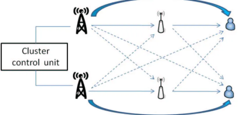
1.1 Topology of a two-cell cooperation group. . . 6
1.2 Another representation of a two-cell cooperation group. Solid lines and whereas dashed lines indicate useful transmission and interference
respec-tively. . . 7
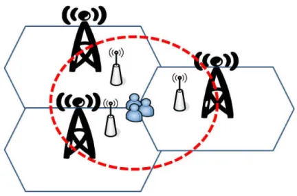
2.1 Topology of a three-cell cooperation group. . . 10
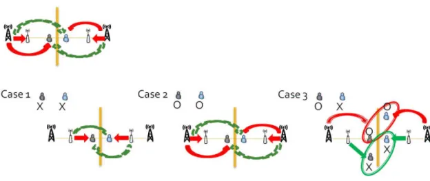
2.2 Three possible cases next to coordinated BSs transmission in a two-cell cooperation group. Solid lines and whereas dashed lines indicate useful
transmission and interference respectively. . . 11
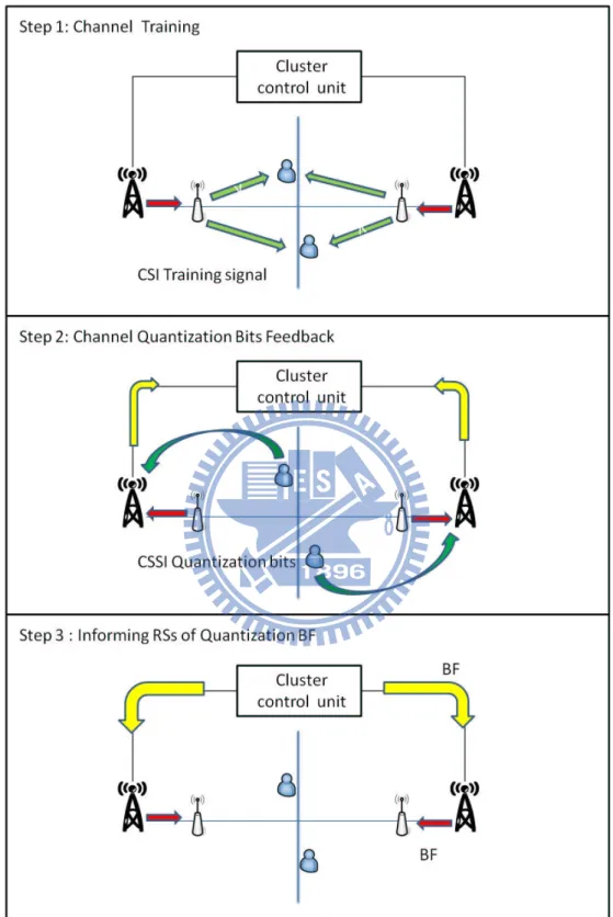
2.3 Flow chart of designing beamforming at cluster control unit for every
relay station in a cooperation group. . . 12
7.1 An illustration for a subnetwork of 3 SSs. . . 36
7.2 Simulated throughput when N=3 and `0 = 0: (a) Order of path loss=3
(b) Order of path loss=4. The variance of channel between BSs and RSs
and of AWGN noise are both assumed as one. . . 37
7.3 Simulated throughput when N=3: (a) `0 = 0 (b) P0 = 10 dB. . . 38
7.4 Feasible rates versus the target SINR when N=2. . . 39
7.5 Feasible rates versus the upper limit, ²,on channel uncertainties when
7.6 Subplot (a) shows the average power consumptions versus the target
SINR, γ0, and subplot (b) presents the feasible rates versus γ0, both at
²=0.1. . . . 40
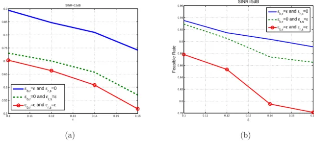
7.7 Feasible rates versus the upper limit, ²r,s, on channel uncertainties when
subplot (a) γ0=15dB, and subplot (b)γ0=5dB . . . 41
7.8 Feasible rates and power consumption versus the target SINR, γ0, when
²r,s=0.1. . . 42
7.9 Subplot (a) shows the average power consumptions versus the target
SINR, γ0, and subplot (b) presents the feasible rates versus γ0, both at
Abstract
Relay-assisted coordinated multi-point (CoMP) beamforming (BF) methods are studied to support quality of service (QoS) in Automatic Retransmission reQuest (ARQ) for downlink multi-cell networks. Considering the design constraints and the feasibil-ity of CoMP transmissions, two types of robust CoMP amplify-and-forward (AF) BF methods are proposed to maintain the signal to interference-plus-noise ratio for each subscriber station (SS) in the network subject to imperfect knowledge on the channel state information. Simulation results show that the proposed low-complexity algorithm can provide near optimal performance and the downlink throughput for SSs close to cell boundaries can be drastically improved via CoMP relaying. Besides, the proposed robust CoMP BF methods not only can reduce the system power consumption, but also can increase the feasibility to support QoS in ARQs even with the low-complexity AF relaying.
Chapter 1
Introduction and System
Architecture for CoMP AF
Beamforming
Coordinated multipoint (CoMP) transmission with multiple-input multiple-output orthogonal frequency division multiplexing (MIMO-OFDM) is one of the promising con-cepts to improve cell edge user data rate and spectral efficiency in Long Term Evolution (LTE) or Worldwide Interoperability for Microwave Access (WiMAX). In addition to CoMP transmissions , relaying has also been proposed to International Mobile Telecom-munication (IMT)-Advanced to improve cell coverage and signal-to-interference plus noise ratio (SINR) of cell edge subscriber stations (SSs) . Integrating the concept of CoMP transmissions and coordinated relaying, this work focuses on robust beamform-ing designs which concern about maintainbeamform-ing the quality of service (QoS) of each SS under the influences of channel quantization errors in a multi-cell wireless environments. In general, coordinated BSs transmission can be categorized as inter-site CoMP and intra-site CoMP. Inter-site CoMP performs the cooperation among BSs in different cells, while intra-site CoMP only performs the cooperation among the sectors of one BS.
Al-though, compared to intra-site CoMP, inter-site CoMP would be much harder to realize due to existing challenges such as clustering, scheduling, synchronization, backhaul over-head, channel state information (CSI) feedback load and CSI estimation accuracy [1], the design of inter-site CoMP still attracts many research attention as it provides promis-ing gains in system throughput [1]. To fully exploit the potential of inter-site CoMP processing, the coordinated BSs should jointly transmit to multiple SSs, where each SS is simultaneously served by coordinated BSs and therefore both data and channel state information (CSI) are exchanged between the BSs [1]. In this case the coordinated system actually becomes a single-cell multi-antenna system which is known as a vir-tual MIMO network, and existing downlink beamforming approach has been proposed in [2]. The main issue with [2] is that this scheme requires data sharing between the BSs, which is forbidden when limited backhaul is allowed. Motivated by this, [3] looked into coordinated beamforming (BF) schemes without data sharing among the BSs.
In spite of the potential of inter-site CoMP processing, the tradeoffs between the cost to provide CSI at the transmitter (CSIT), estimation error, and system resource allocated to training appears that the number of antennas that can be jointly coordinated (either on the same BS or across multiple BSs) is essentially limited [4]. In addition, to avoid executing the complex BF design for multiple BSs joint processing, limited MIMO network coordination is more practical and still yield a significant throughput gain, e.g., throughput increases to a factor of 2.5 by coordinating a cluster of seven cells [5]. For these purposes, several cells form a cluster, and a cluster control unit (CU) exists to collect CSIs, perform beamforming design and coordinate coherent transmissions in this system. Specifically, an adaptive clustering algorithm is required. Field trial results show that in spite of various aforementioned implementation constraints downlink CoMP transmission still be realized in real-world scenarios and that significant gain can still be achieved by forming small coordinated clusters in large-scale networks [1]. An extension and analysis of CoMP architecture in large multi-cell networks is also proposed and
investigated in [6].
Due to the essential constraints on CSI feedback, synchronization and the number of antennas that can be jointly coordinated, the CoMP architecture is often discussed for Orthogonal Frequency Division Multiple Access (OFDMA) system. A scheduling algorithm is required to jointly allocate the subcarriers for SSs in different cells of a CoMP system [7]. In LTE-Advanced context, subcarriers are allocated in blocks of adjacent subcarriers, which represent the Physical Resource Blocks (PRBs). Channel coherence bandwidth is assumed larger than the bandwidth of a PRB leading to flat fading over each PRB. Several PRBs exist in a coordinated system and each of them might be allocated to one or more SSs. This kind of resource allocation problem of spatially reusing PRBs within a CoMP region is investigated [7].
To perform coordinated BF in a CoMP system, SSs in a cluster need to accurately feed back their CSI to the CU; the CU exchange CSIs between BSs by backhaul. To yield a good tradeoff between the performance and overhead for CoMP systems, an efficient feedback method is proposed in [8],the results show that the reduction of the feedback load can be efficiently exploited to reduce the backhaul load through their proposed scheduling or BF scheme. In CoMP systems, synchronization is also a critical issue. Large distances between the base stations result in inevitable differences in time of arrival between the SSs’ signals. This phenomenon further brings about inter-symbol interference in OFDM systems if the cyclic prefix length is exceeded. Moreover, inter-carrier interference happens because of inter-carrier frequency offsets caused by imperfect oscillators. However, the gain of using CoMP is still demonstrated to be larger than the decline results from synchronization problems according to metrics that can be applied for an approximation of the impact of asynchronization in CoMP systems [9].
Despite the sophisticated MIMO techniques that might be used to suppress the multi-ple access interferences (MAI) in coordinated BSs transmission, SINR at cell boundaries is typically low arising from intrinsically weak received signal coming from the associated
BS, which make it difficult to maintain the quality of service (QoS) in data transmis-sions. To overcome the difficulties, yet to improve the throughput for SSs close to cell boundaries, RSs are deployed for automatic-repeat-request (ARQ) for SSs because of stronger average channel gain of RS-SS links. Furthermore, to achieve high spectral efficiency as coordinated BS systems, the cooperation among RSs in different cells are also considered. The coordinated RSs jointly retransmit to multiple SSs, where each SS is simultaneously served by coordinated RSs.
Generally speaking, in ARQ, the source retransmits if the destination fails to decode data and feeds back negative-acknowledgment. An evolutional and useful ARQ scheme for cooperative relaying using a single RS is proposed in [10]. First, the BS transmits their data to the SS. At the same time, the relay overhears. Then, SSs broadcast a single bit to indicate successful direct transmission or not. If negative-acknowledgment is broadcasted, the relay retransmits. Otherwise, the relay just do nothing and the next transmission round begins. Another existing ARQ protocol is known as two-hop relaying. The BS first transmits their data to the RS and then the RS forwards the received signal to SS. At the end of transmission round, SSs decode only the signal received from the RS [11]. As for the types of relaying methods, two typical approaches are : decode and-forward (DF), which forwards only if successful decoding of data, and amplify-and-forward (AF), which simply amplifies the received signal without any decoding [10]. More detailed discussion about the architecture, feasibility and effectiveness of relaying techniques in LTE-advanced are presented in [12–14].
We have reviewed two coordinated BF schemes. One transforms interference from the other cells into useful signal by exchanging CSIs and data between transmitting nodes. The other one focuses on interference cancelation only by having global CSIs at the CU. Nonetheless, to fully exploit the potential of coordinated transmission, the CU requires to have the global CSI knowledge, which incurr overhead for channel estimation and feedback. Considering the difficulties for acquiring global CSI, coordinated beamforming
design considering partial CSIs at the CU is widely discussed. In the process of acquiring the CSI, the channels are first estimated by the SSs and then are quantized and fed back to the CU. Hence, the available CSIs at the CU are subject to uncertainties that mainly arise from estimation error and channel quantization. With a good estimator and small amount of bits reserved for quantized CSI feedback in the next-generation cellular wireless networks, quantization error is very likely a dominant source of error about the CSIs. To overcome this, we also consider a bounded uncertainty model in the CSIs at the CU. This model is a useful one for systems with low-rate feedback channel [15]. For this bounded channel uncertainty model, we design a BF that minimizes the transmitted power required to ensure that each SS’s SINR requirement is satisfied for all channels within the specified uncertainty region. In this kind of worst-case analysis, which we discuss in this paper, the uncertainty possesses no statistical properties. Similar worst-case analysis considering bounded error model can also be founded in [16–19]. On the other hand, stochastic robustness analysis, in which the error model is assumed possessing statistical properties has also been investigated in [20, 21]. In contrast, a distributed beamforming design is carried out to avoid the overhead from another point of view based on a cooperative game theory proposed [22]. The main idea of non-cooperative game theory is that each SS may try to compete for the scarce resource and optimize its own performance based on its local CSIs.
Because of the limitation of the number of antennas that can be jointly coordinated, we assume each PRB of can only be assigned to one SS in a cell and served by its associated BS and RS via this PRB. With this assumption, we disscuss our coordinated downlink beamforming design under a cooperation group composed of several cells at each of which a single BS and a amplify-and-forward (AF) RS are located. A two-cell cooperation group is illustrated in Fig. 1.1 and Fig. 1.2.
As for RSs retransmission, in spite of the stronger channel gain of RS-SS links result-ing in each SS’ strong desired received signal from their associated RSs, a critical issue is
Figure 1.1: Topology of a two-cell cooperation group.
that simultaneous retransmission from different relays on the same sub-channel leads to cross-cell interference to SSs in the other cells. Fortunately, similar problems also exist in coordinated BS beamforming designs and two well-known coordinated BS beamforming schemes on the interference mitigation of BSs-SSs links have been surveyed in the pre-vious introduction [2, 3]. With the help of similar techniques, high-quality coordinated RSs retransmission is promising. However, different from BSs, resource allocated for exchanging information between RSs is commonly assumed to be extremely limited and hence virtual MIMO network is almost impossible in real-world. The other coordinated BF technique that only requires CSIs at the CU is more practical for coordinated RS BF. Even though exchanging data between BSs is more realistic, the same coordinated BF technique is preferable for coordinated BS BF as usual. Furthermore, to avoid QoS decline of each SS resulting from constrained cooperation between RSs, we discuss a scheme in which low-rate quantization for channel feedback is asked and no direct CSIs exchange between relays is allowed. We also investigate worst-case robust beamforming design which concerns about maintaining the QoS of each SS in the existence of channel quantization error as multi coordinated cells transmission and relaying are integrated. More detailed explanation and justification about the process of acquiring CSIs of the CU in this system is discussed in the next section.
Figure 1.2: Another representation of a two-cell cooperation group. Solid lines and whereas dashed lines indicate useful transmission and interference respectively.
A similar integration of multi-cell coordinated transmission and relaying are also in-vestigated [23]. However their interference mitigation schemes are quite different from that of our work. Following their illustrations, BSs-RSs links can be treated as broad-cast channel or interference channel depending on the existence or absence of a backhaul connection between BSs. On the other hand, RSs-SSs links are regarded as an interfer-ence channel because of the absinterfer-ence of backhaul connection between RSs. The authors show that interference of broadcast channel and interference channel can be mitigated by using Dirty-Paper Coding [24] and Han-Kobayashi Coding [25] respectively.
Despite the rich results about the worst-case analysis of amplify-and-forward relaying for bounded error model [26], [27], robust beamforming based on integration of coordi-nated BS transmission and RS retransmission has not been studied. We first formulate the robust BF designs considering herein as a Semidefinite Programming (SDP) based on the S-Procedure [28] and semi-definite relaxation (SDR) [29]. We then develop nec-essary conditions for the optimal beamforming for the robust BF problem and develop a suboptimal and nearly closed-form expression of the BFer based on a two-tier iter-ated QCQP. The SDR-based beamforming method is shown by simulations to achieve the near optimal performance. And the performance of the low-complexity suboptimal scheme based on the iterated QCQP is shown to be very close to that with the SDR
approach, and is more friendly for practical implementations. Simulation results also show that the downlink throughput for SSs close to cell boundaries of the multi-cell system can be drastically improved via CoMP AF relaying. The proposed robust CoMP AF BF methods is a promising scheme to compromise the two factors of performance, the system power consumption and the feasibility to support QoS in ARQs.
Notations: We follow the conventions to use lowercase letters, e.g., a, to represent
scalars, boldfaced lowercase letters, e.g., a, to represent vectors and uppercase letters, e.g., A, to represent matrices. vec(·) stands for concatenating the columns of the matrix
argument into a vector. [a]i stands for i-th entry of vector a. [A]i,j stands for the (i,j)
entry of matrix A. k · k represents the vector Euclidean norm. The superscipts ’T’, ’H’ and ’-1’ represent transpose, Hermitian transpose, and inverse of matices. A º 0 means
that matrix A is positive semidefinite. The notations Ci×j and Ri×j represent the sets
of i×j-dimentional complex and real matrices. For simplicity, ∀i , {i = 1 . . . N} and
Chapter 2
Transmission Protocol and Problem
Setting for CoMP AF Beamforming
We disscuss our coordinated downlink beamforming design under a cooperation group of N cells, each of which consists of a single BS, a amplify-and-forward (AF) RS and a SS. The topology of a three-cell cooperation group is shown in Fig. 2.1. To maintain the signal quality received at the RSs, RSs are placed between the BSs and the SSs, and are still in a fair distance away from their cell boundaries to overhear and forward signals to SSs near the cell boundaries. Consequently, the interferences to a RS from the BSs of its adjacent cells are very small. Next, we carefully show transmission mechanism, challenges and our solutions in this system.
The transmission scheme of a cooperation group is introduce below based on a two-cell cooperation group example as shown in Fig. 2.2, and this example can be generalized to N-cell cases. In the first transmission round of a cooperation group, the scheduler would first choose two SSs in different cells and then coordinate BSs in this group to transmit data to these SSs. At the end of transmission round, SSs would decode the packet and detect the error. If both the SSs detect errors, scheduler would coordinate
Figure 2.1: Topology of a three-cell cooperation group.
RSs to retransmit data to these SSs in the next transmission round. If both the SSs do not detect any error, scheduler would coordinate BSs to continue transmitting data to these SSs. However, if only one SS detect errors, scheduler would choose a new parter for them respectively to form a new direct transmission group and retransmission group. To design CoMP BF, the CU requires having knowledge of global CSIs and informs transmitting nodes of their adequate beamforming matrices or vectors. Existing works have been carefully investigated the feasibility of coordinated BSs transmission [1]. How-ever, there are few literatures discussing the design of coordinated transmission among RSs in different cells. Here, we propose a scheme for it. By retransmission of RSs, data is actually passed through BS-RS and RS-SS links. Hence, CSIs of those links are required for BF design. To acquire these CSIs, training signals are transmitted, estimated CSIs are fed back by RSs or SSs to their associated BSs and then RSs are informed of their own beamforming matrices by their own associated BSs. The flow chart is shown in Fig. 2.3.
To yield optimal performance, the CU and RSs require complete knowledge of CSIs and of their own BF matrices respectively. In this work, we assume RSs are able to have complete knowledge of their own BF matrices. However, due to the amount of bits
Figure 2.2: Three possible cases next to coordinated BSs transmission in a two-cell cooperation group. Solid lines and whereas dashed lines indicate useful transmission and interference respectively.
reserved for quantized CSI feedback is small in the standards for the next-generation wireless cellular networks, full CSI at the CU is impractical and hence we consider a uncertainty region which is useful and common to model quantization error. And we also design BF based on criterion of minimizes the transmitted power required to ensure that each user’s QoS requirement is satisfied for all channels within this specified region. Besides, those trivial and weak interference links ( i.e., links between BSs and their non-associated RSs) are neglected in our analysis. Similar relaxation is also common for CoMP system to yield a good tradeoff between performance and CSIs feedback overhead [8]. In addition, by neglecting those trivial interferences, optimal BF matrices for each RS are shown to possess a specified structure, which results in reducing computation effort of BF design at the CU and decreasing resource reserved for informing RSs of their own BF.
Figure 2.3: Flow chart of designing beamforming at cluster control unit for every relay station in a cooperation group.
Chapter 3
System Model for CoMP AF
Beamforming
Under the system architecture introduced previously, RSs of a cell receive signals only
from their associated BS. In contrast, a SSi close to the edge of its cell Ci, will receive its
desired signal from BSi or its associated RSi, and meanwhile pick up interferences from
BSj or RSj, ∀j 6= i. To suppress the interferences efficiently in coordinated transmissions
without data sharing, each BS or RS must be at least equipped with N antennas (We assume just N antennas in this paper), while each SS is assumed having one antenna only. Besides, we assume perfect channel state information at the receiver (CSIR), while partial CSI at the CU caused by quantization error is considered. Also, we assume RSs have complete knowledge of their own BF matrices.
Here, we just illustrate system models for coordinated BSs transmission and
coordi-nated RSs retransmission. Signals sent from BSs and received by SSi can be modeled
as ysi = N Σ j=1h H bj,siwbjxj + nsi (3.1)
where xj stands for the data symbols of unit power sent for SSj from BSj , and wbj ∈
of BSj to the antenna of SSi are modeled as flat Rayleigh faded and are denoted by
hbj,si ∈ CN ×1. Besides, the noise nsi ∈ C is zero-mean complex Gaussian distributed
with its variance equal to σ2, denoted by n
si ∼ CN (0, σ2). The total average transmit
power of the BSs is Pb = ΣNi=1kwbik
2. Given σ2, h
bj,si and wbj, ∀i, j, the SINR observed
at SSi for signals sent from BSs can be expressed as
SINR(b)i = |h H bi,siwbi| 2 P j6=i |hH bj,siwbj|2+ σ2 (3.2)
On the other hand, the signal received at the relay RSi is modeled as
yri = hbi,rixi+ nri (3.3)
where hbi,ri = Hbi,riwbi.
Since the interferences from BSj, ∀j 6= i, of adjacent cells are negligible in our system
setting. The noise vector nri ∈ CN ×1 is ∼ CN (0, σ2IN), and the channel coefficient
between each antenna pair from BSi to RSi is also modeled as flat Rayleigh faded.
Thus, the channel coefficients can be expressed in a matrix form of Hbi,ri ∈ C
N ×N.
However, hbi,ri ∈ C
N ×1 can be regarded as equivalent channel coefficients between BS
i
and RSi.
Consider simple ARQs with coordinated AF BF in our system architecture. The
signals received at SSi from RSj, ∀j, in ARQ phases can be expressed as
yri,si = h H ri,siWriyri + P j6=ihHrj,siWrjyrj + nsi (3.4) where Wri ∈ C
N ×N is the BF matrix employed by RS
i in Ci and hrj,si ∈ C
N ×1 stands
for the channel vector from RSj to SSi. Again all coefficients in hrj,si are still modeled
as flat Rayleigh faded. Given σ2 and h
relays is defined as
Pr , ΣNi=1[kWrihbi,rik
2+ σ2trace(WH
riWri)] (3.5)
The SINR observed at SSi for signals sent from RSi, ∀i, can thus be expressed as
SINR(r)i = |h H ri,siWrihbi,ri|2 P j6=i |hHrj,siWrjhbj,rj|2+ ( P j khHrj,siWrjk2+ 1)σ2 (3.6)
According to the aforementioned system setting and signal model, we study in the sequel coordinated AF BF methods for CoMP ARQ in order to maintain the SINR for
SSi, ∀i, in the sub-network.
As mentioned previously, to avoid heavy overhead caused by data sharing, we note
that the data xi for SSi are still sent through their associated BSi or RSi inside the
sub-network only. Given σ and hbj,si, ∀i, j,, the BF, wbi, can be jointly designed to meet
a target SINR, γ0, for each SSi, which is known as SINR constrained power minimization
problem of base stations (SPMP-BS). SPMP-BS
min
{wbi}Ni=1
Pb s.t. SINR(b)i ≥ γ0, ∀i
Furthermore, given σ2, h
bi,ri, and hrj,si, ∀i, j, the beamformers Wri for RSi can be
jointly designed to meet the target SINR γ0 as well, according to SINR constrained
power minimization problem of relay stations (SPMP-RS). SPMP-RS
min
{Wri}N
i=1
Pr s.t. SINR(r)i ≥ γ0, ∀i
The design methodology outlined in SPMP-BS and SPMP-RS requires the full CSI for hbj,si, hrj,si and hbj,si, ∀i, j.
in our designs, they are modeled as
hbj,si , ¯hbj,si + ebj,si ∀i, j
hrj,si , ¯hrj,si+ erj,si ∀i, j
hbi,ri , ¯hbi,ri+ ebi,ri ∀i
(3.7)
where ¯hbj,si, ¯hrj,si and ¯hbi,ri are quantized channel available at the CU, and ebj,si and
erj,si ∈ C
N ×1 and e
bi,ri ∈ C
N ×1 are their associated unknown uncertainty vectors or
matrices. According to the uncertainty models, the design criterion for wbi is modified
into robust SINR constrained power minimization problem of base stations (RSPMP-BS) RSPMP-BS min {wbi}N i=1 Pb s.t. SINR(b)i ≥ γ0, ∀i ∀ kebj,sik ≤ ²b,s, ∀i, j
where the SINR(b)i still has the form of (3.2) while hbj,siin (3.2) is replaced by ¯hbj,si+ebj,si.
This optimization criterion guarantees that the SINR is satisfied for all ebj,si, ∀i, j, as
long as kebj,sik ≤ ²b,s.
Considering channel quantization error, ebi,ri are actually influence the total transmit
power of relays, Pr, and make it fluctuate even BF matrix Wri are fixed. Hence, one
kind of reasonable cost function is defined as minimizing the maximal transmit power.
Hence, we reconsider a robust design criterion for Wri called as general robust SINR
constrained power minimization problem of relay stations (GRSPMP-RS) GRSPMP-RS min {Wri}N i=1 max {ebi,ri}N i=1 Pr s.t. SINR(r)i ≥ γ0, ∀i ∀ kerj,sik ≤ ²r,s, ∀i, j ∀ kebi,rik ≤ ²b,r, ∀i
where Pr and SINR(r)i still have the form of (3.5) and (3.6) while hrj,si and hbi,ri in (3.6)
A relaxed version of GRSPMP-RS named as robust SINR constrained power mini-mization problem of relay stations (RSPMP-RS) is also considered in this paper.
RSPMP-RS min
{Wri}Ni=1
Pr s.t. SINR(r)i ≥ γ0, ∀i
∀ kerj,sik ≤ ²r,s, ∀i, j
where Pr and SINR(r)i still have the form of (3.5) and (3.6) while hrj,si in (3.6) are
replaced by ¯hrj,si + erj,si.
The signal models and design criteria introduced above allow us to construct the beamformers for coordinated BSs transmissions and for coordinated RSs retransmissions. In the next section, we first introduce our CoMP AF BF algorithms according to SPMP-RS. The robust AF BF algorithms are provided in Section 5 and 6.
Chapter 4
SINR Constrained CoMP AF
Beamforming
In this chapter, we first assume no quantization error (i.e., unlimited rate for channel feedback) and therefore solve problem SPMP-RS. However, this optimization problem
includes so many (N3) primal variables that it seems requiring very huge computation
effort at the CU. Besides, N-by-N BF matrices for RSs lead to require high downlink transmission resource reserved for informing RSs of their own BF.
Fortunately, with help of the following lemma, optimal BF matrix for each RS are shown to be rank one at this case. The rank one BF matrix for a certain RS can be decomposed as a column vector and a row vector. This row vector is actually composed of equivalent CSIs between its associated BS and itself. Hence, these CSIs may be estimated by itself and only a vector rather than a matrix needs to be transmitted by its associated BS, which lead to decrease resource reserved for informing RSs of their own BF. Furthermore, with knowledge of the form of a good BF, we may also reduce computation effort of BF design at the CU, which results from fewer optimization variables should be considered.
programming (SOCP), to develop an approach which is more friendly for practical im-plementations and to gain more insight into the problem, we then provide optimality conditions in the following proposition, and suggest a simple fixed point iteration for finding the variables that satisfy them.
Lemma 1. Optimal CoMP AF beamforming matrix of SPMP-RS W∗ri, ∀i, are necessary
rank one and always can be decomposed as below
W∗ri = wihHbi,ri (4.1)
where wi ∈ CN ×1.
Proof. From Lagrangian zero derivative condition which is actually necessary for
opti-mality, Wri can be just represented as the form of (4.1) by some mathematical
manip-ulations. The details of derivations are summarized in APPENDIX A.
Based on Lemma 1, CoMP AF beamforming matrix Wri of SPMP-RS can be
as-sumed as wri
hH bi,ri
khbi,rik, where wri ∈ CN ×1, without generality, and hence can be easily
reformulated into an equivalent problem called transformed SINR constrained power minimization problem of relay stations (TSPMP-RS)
TSPMP-RS min p0,{wri} N i=1 p0 s.t. N Σ i=1cikwrik 2 ≤ p 0, 1 γ0w H riAiwri ≥ N Σ j=1,j6=iw H rjBj,iwrj+ σ2, ∀i where Ai , di ¡ hri,sih H ri,si ¢ , Bj,i , cj ³ hrj,sih H rj,si ´ for j 6= i, ci = (khbi,rik2+ σ2) and di , (khbi,rik2− γ0σ2).
Clearly, both Bj,i are positive semi-definite (p.s.d.), j 6= i ∀i, j, denoted by Bj,iº 0.
Thus, there exist Ri ∈ CN
2×N2 such that NΣ j=1,j6=iw H rjBj,iwrj , kR H i wk2, where wH = (wH r1, · · · , w H
rN). Moreover, supposed that {w
∗
r1, . . . , w ∗
vec-arbitrary θi, ∀i. Thus, without the loss of generality (w.l.o.g.), one can assume that
(ei⊗
√
dihHri,si)w ≥ 0, where ei is a N-dimensional unit vector with one for the i-th entry
and zeros elsewhere. As a result, the SINR constraint in TSPMP-RS can be further reformulated as ai(w) , ¡ai(w) ai(w)T ¢T , µ 1 √ γ0(ei⊗ p dihHri,si)w (R H i w)T σ ¶T ºK 0 (4.2)
where the notation v ºK 0, vH , [v, vH] denotes a generalized inequality: v ≥ kVk.
Similarly, having p ,√p0, the power constraint in TSPMP-RS can also be reformulated
as p(p, w) ,¡p (SHw)T¢T º
K 0, where S ∈ CN
2×N2
. Consequently, TSPMP-RS can be cast into the form of the standard second order cone programming (SOCP) [30] which can be solved by available optimization solvers, e.g. CVX [31]. However, the general-purpose solvers are typically computationally inefficient for a specific optimization problem like TSPMP-RS. To reduce the complexity for CoMP AF BF, we propose a nearly closed-form method for solving TSPMP-RS, which is summarized in the following proposition.
Proposition 1. Consider TSPMP-RS. If there exist λi > 0, ∀i,that satisfy
λi = γ0 dihHri,si µ ciIN + N Σ j=1,j6=iλjBi,j ¶−1 hri,si (4.3)
then the minimum transmit power Pr is equal to ΣNi=1λiσ2.
Define δi , σ r N Σ j=1[F −1]
i,j in which the entry of the N × N matrix F are given by [F]i,i , (λri0di)2hHri,si(ciIN+ N Σ j=1,j6=iλjBi,j) −1 Ai r0(ciIN+ N Σ j=1,j6=iλjBi,j) −1h ri,si; otherwise, for i 6= j, [F]i,j , −(λrj0dj)2hHrj,uj(c n √ iIN + N Σ j=1,j6=iλjBi,j) −1B j,i(ciIN + N Σ j=1,j6=iλjBi,j) −1h rj,uj.
The optimal wri, ∀i, are given by
wri = λidiδi γ0 µ ciIN + N Σ j=1,j6=iλjBi,j ¶−1 hri,si. (4.4)
Proof. As the statements above, TSPMP-RS actually can be represented as min w kS Hwk2 s.t. kRH i wk2− |√1γ0(ei⊗ √ dihHri,si)w| 2+ σ2 ≤ 0 (4.5)
In [30], the authors has shown that Karush-Kuhn-Tucker (KKT) conditions are just sufficient and necessary for optimality considering those problems with the same form as (4.5). Hence, CoMP AF BF provided in this proposition are just derived from KKT conditions and must be optimal. The other details are summarized in APPENDIX C.
To efficiently find feasible λi satisfying (4.3), fixed-point iterations are done as below
and can be shown to converge given any initial λ(0)i > 0 in APPENDIX B.
λ(n+1)i = fi(Λ(n)) , γ0 dihHri,si µ ciIN + N Σ j=1,j6=iλ (n) j Bi,j ¶−1 hri,si (4.6) where Λ = [λ(n)1 , . . . , λ(n)N ].
Proposition 1 provides a simple method to design the BF matrices for RSs to meet
the same target SINR, γ0, for each SS in the subnetwork with CoMP AF relaying. On
the other hand, individual weighting factors can be used to scale Ai in TSPMP-RS for
Chapter 5
Robust SINR Constrained CoMP
AF Beamforming
According to CSIs feedback flow chart illustrated in chapter 2, CSIs of BS-RS and RS-SS links are fed back by BS-RS and BS-SS reverse links respectively . Comparing to channel feedback by BS-SS reverse links, BS-RS reverse links usually possess larger channel gain and feedback-link capacity, because RSs are much nearer to BSs than SSs. At this case, more bits are allowed to quantize CSIs of BS-RS links and then CSIs of these links at the CU are within a much smaller specified uncertainty region.
Hence, in this chapter, we first only consider dominant source lead to performance loss. That is, we consider CSI quantization error of RS-SS limks (i.e., limited feedback of reverse BS-SS links ) but no CSI quantization error of BS-RS links (i.e., unlimited feedback of BS-RS reverse links ). Hence, a robust coordinated AF RSs downlink BF design known as RSPMP-RS is addressed, and CSI quantization error of all links would be further considered in the next chapter.
As illustrations of the previous chapter, a similar lemma is proposed and suggests that optimal BF matrices for each RS is rank one and possess a specified structure,
which may reduce computation effort of BF design at the CU and decrease resource reserved for informing RSs of their own BF.
In addition to formulating RSPMP-RS into a Semidefinite Programming (SDP) based on the S-Procedure and semi-definite relaxation (SDR) [28], to develop an approach which is more friendly for practical implementations and to gain more insight into the problem, we then provide necessary conditions for optimality in the following proposi-tion, and suggest a simple two-tier fixed point iteration (as shown in the following algo-rithm) based on iterated quadratic constraints quadratic programming (QCQP) concept for finding the variables that satisfy them.
The SDR-based beamforming method is shown by simulations to achieve the nearly optimal performance. And the performance of the low-complexity suboptimal scheme based on the iterated QCQP is shown to be very close to that with the SDR approach, and is more friendly for practical implementations.
Lemma 2. Optimal robust CoMP AF beamforming matrix for RSPMP-RS W∗
ri, ∀i, are
necessary rank one and always can be decomposed as below
W∗ri = wihHbi,ri (5.1)
where wi ∈ CN ×1.
Proof. The idea of proof is just similar to Lemma 1’s, and the details of derivations are
also summarized in APPENDIX A.
Based on Lemma 2, robust CoMP AF beamforming matrix Wri can also be assumed
as an equivalent problem called as wri
hH bi,ri
khbi,rik, where wri ∈ CN ×1, without generality.
RSPMP-RS can be then reformulated as transformed robust SINR constrained power minimization problem of relay stations (TRSPMP-RS)
TRSPMP-RS min {wri}N i=1 N Σ i=1cikwrik 2 s.t. SINR(r) i ≥ γ0, ∀i ∀kerj,sik ≤ ²r,s, ∀i, j
And the SINR(r)i can also be rewritten as
where SINR(r)i = khbi,rik 2D i,i Σ j6=ikhbj,rjk 2D j,i+ (Σ j Dj,i+ 1)σ 2 (5.2) where Dj,i , |(¯hrj,si + erj,si) Hw rj| 2.
The problem above ensures that every SS will be served with an SINR at least better
than the target SINR, γ0, for all channel uncertainties, erj,si, whose kerj,sik ≤ ²r,s.
This, in fact, will impose an infinite number of non-convex constraints in this problem. Although the non-convex constraints can be transformed into convex ones with a method similar to what employed in Chapter 4, the approach used in Proposition 1 is still not capable of dealing with an infinite number of convex constraints. Hence, to solve TRSPMP-RS, the first challenge is to transform the infinite constraints into finite ones. We, in the sequel, present two methods to overcome the difficulty, which lead to two different approaches for solving TRSPMP-RS.
5.1
RSPMP-RS based on the S-Procedure and SDR
Following a procedure similar to what presented in [32–34], the infinite number of con-straints in TRSPMP-RS can be transformed into a finite number of linear matrix in-equalities (LMIs), using the S-procedure [28]:
inequalities vHAv + bHv + vHb + c ≥ 0, ∀vHCv ≤ 1 hold if only if ∃λ ≥ 0 such that A + λC b bH c − λ º 0. (5.3)
Then, we introduce auxiliary variables tj,i, ∀i, j, to help us reformulate TRSPMP-RS
before we can apply S-Procedure. The resultant reformulation is given by min {tj,i≥0}Ni,j=1,{wri} N i=1 N Σ i=1cikwrik 2 s.t. di
γ0Di,i ≥ ti,i, cjDj,i ≤ tj,i, j 6= i, ∀i, j N Σ j=1,j6=itj,i+ σ 2 ≤ t i,i, ∀i ∀ kerj,sik ≤ ²r,s, ∀i, j (5.4)
Based on this reformulation, we want to recast TRSPMP-RS into a semi-definite programming (SDP). We present the process step by step as follows.
1. Reformulate Dj,i into quadratic functions of erj,si:
cjDj,i , cj|(¯hrj,si+ erj,si) Hw rj| 2 = eHrj,siWrjerj,si+ e H rj,siWrjh¯rj,si + ¯h H rj,siWrjerj,si+ ¯h H rj,siWrjh¯rj,si where Wrj , cjwrjwHrj
2. Transform the infinite inequalities in (5.4) into LMIs via the S-Procedure:
According to Proposition 2, cjDj,i ≤ tj,i holds for all kerj,sik ≤ ²r,u, if and only
if there exists a number λj,i ≥ 0 such that the matrix (5.3) is p.s.d. if we have
v , erj,si, A , −Wrj, b , −Wrjh¯rj,si, C , 1 ²2 r,sI, c , tj,i − ¯h H rj,siWrjh¯rj,si and
λ , λj,i. Following the similar steps, the constraints, γd0iDi,i ≥ ti,i, ∀ keri,sik ≤ ²r,u,
3. Relax the rank-one constraint on Wrj, ∀i:
By doing this, the LMIs obtained above for di
γ0Di,i and cjDj,i ≤ tj,i, j 6= i can be
expressed in convex forms. In other words, (5.4) can be relaxed and expressed in a SDP of the form min Wrj,tj,i≥0,λj,i≥0 N Σ i=1tr(Wri) s.t. di ciγ0 ¯ HH ri,siWriH¯ri,si+ Blkdiag n λi,i ²2 r,sIN, −(ti,i+ λi,i) o º 0, ∀i Blkdiag n λj,i ²2 r,sIN, tj,i− λj,i o − ¯HH rj,siWrjH¯rj,si º 0, ∀j 6= i N Σ j=1,j6=itj,i+ σ 2 ≤ t i,i, Wri º 0 ∀i (5.5)
where ¯Hrj,si , (IN h¯rj,si), ∀i, j and the function Blkdiag{A, B} puts its square
matrix arguments into a block diagonal one.
The above SDR problem can be solved with the available optimization solvers such as SeDuMe or CVX [31, 35]. In fact, the beamformers obtained with the SDR approach
are optimal if they satisfy the rank-one condition. Although the resultant Wri, are
not guaranteed to be rank-one ∀i, by inspection from our simulations, we notice that the solutions always satisfy the rank-one condition. Similar observations have been previously reported in [32–34]. Thus, the above SDR approach (5.5) can be practically considered as an nearly optimal solver for RSPMP-RS.
5.2
RSPMP-RS based on Iterated QCQP
The SDR-based approach presented in the previous section is elegant and provides a practically nearly optimal solver. However, the approach relies on a numerical toolbox which is not always available and less friendly for practical implementations. Motivated by the results in [36, 37], among others, we present in the sequel a more intuitive and commonly used approach to relieve the infinite number of constraints in TRSPMP-RS, making use of the triangular and the Cauchy-Schwarz inequalities. Nevertheless,
to resolve the conservativeness often seen in this approach, we introduce a number of auxiliary variables to ensure the tightness in the process of constraint relaxations, which together with a new formulation for programming leads to a nearly closed-form suboptimal solver. The suboptimal solver presents a performance very close to the one obtained with the SDR-approach in (5.5), yet is more computationally efficient and friendly for practical implementations. Moreover, it provides us an insight into the structure of the robust CoMP AF beamformers. Details of the derivations are presented below and in the Appendix C.
Recall TRSPMP-RS. To relieve the infinite number of constraints in programming,
we need to bound the effects of uncertainties in Di,i, and Dj,i of (5.2) for all possible
erj,si that satisfy kerj,sik ≤ ²r,s, ∀i, j. Observing the form of Dj,i in (5.2), erj,si are
embedded in |eH
j,iwri| which can be upper bounded with the Cauchy-Schwarz inequality
as follows
|eHrj,siwrj| ≤ kerj,sikkwrjk ≤ ²r,skwrjk ∀i, j. (5.6)
This upper bound is in fact tight for TRSPMP-RS as there exist erj,si that just make
the inequlities also satisfy equality. Substituting this upper bound into Di,i followed by
some mathematical manipulations, we obtain
Di,i = |(¯hri,si+ eri,si)Hwri|2 ≥ (|¯h H ri,siwri| − |erHi,siwri|)2 ≥ |¯hHri,siwri| 2− 2² r,u|¯hHri,siwri|k ˜wrik + ² 2 r,skwrik 2
if |¯hHri,siwri| ≥ ²r,skwrik. This lower bound can further be expressed in a quadratic form
if we define some parameters vi,i, ∀i, such that |¯hHri,siw
H ri| ≤ vi,ik¯hri,sikkwrik, which is Di,i≥ wHri h ¯ hri,sih¯ H ri,si + ¡ ²2 r,s− 2²r,uvi,ik¯hri,sik ¢ IN i wri. (5.7)
To meet |¯hHri,siwri| ≥ ²r,skwrik, the parameter vi,i must also satisfy vi,i ≥
²r,s
procedure, we have Dj,i = |(¯hrj,si + erj,si) Hw rj| 2 ≤¡|¯h rj,siwrj| + ²r,skwrjk ¢2 (5.8) ≤ wH rj h ¯ hrj,sih¯ H rj,si + ¡ ²2 r,s+ 2²r,uvj,ik¯hrj,sik ¢ IN i wrj. (5.9)
Based on (5.7) and (5.9), TRSPMP-RS can be reformulated as min wri,vj,i N Σ i=1cikwrik 2 s.t. 1 γ0w H riAˆiwri ≥ N Σ j=1,j6=iw H rjBˆj,iwrj+ σ 2, ∀i |¯hH rj,siw H rj| ≤ vj,ik¯hrj,sikkwrjk, ∀i, j vi,i ≥ k¯h²r,s
ri,sik, vj,i ≥ 0, ∀i, j
(5.10) where ˆAi , di n ¯ hri,sih¯ H ri,si+ ¡ ²2 r,s− 2²r,uvi,ik¯hri,sik ¢ IN o , di , (khbi,rik2 − γ0σ2) and ˆ Bj,i, cj n ¯ hrj,sih¯ H rj,si + ¡ ²2 r,s+ 2²r,uvj,ik¯hrj,sik ¢ IN o for j 6= i.
The infinite number of constraints in TRSPMP-RS have been relieved and refor-mulated into finite ones in (5.10). And the tightness of the new constraints can be
preserved if one can find the optimal v∗
i,i, vj,i∗ and w∗rj that satisfy the equalities of
|¯hH
ri,siw
H
ri| = vi,ik¯hri,sikkwrik and vj,ik¯hrj,sikkwrjk = |¯h H
rj,siwrj|. Although, the
formula-tion of (5.10) is not in convex form, given vi,i and vj,i, the programming can be viewed
as a form of the quadratic constrained quadratic programming (QCQP) model in [30],
or vice versus, which will provide an optimal w∗
ri given the optimal set of parameters:
v∗
i,i and v∗j,i. We next present an iterative framework to find the parameter set and wri
according to the KKT conditions of (5.10). Given that the constraints of (5.10) are in general not convex, the iterative method only guarantees that the solutions satisfy the necessary conditions for (5.10). Even though we do not obtain an algorithm to find the optimal solutions, simulation results show that the resultant beamformers perform almost the same as do the ones obtained with the SDR-based approach.
Proposition 3. Consider the KKT conditions of (5.10). Define the dual variables, λi
and τi,j, ∀i, j. If there exist positive λi, ∀i, that satisfy
λi = γ0 dih¯Hri,siΦ −1 i,ih¯ri,si (5.11)
and τi,j, ∀i, j, that satisfy
τi,i = ²r,sdiλi γ0vi,ik¯hri,sik τj,i= ²r,scjλi vj,ik¯hrj,sik ∀j 6= i (5.12)
then the zero derivative conditions of KKT hold true. where Φi,i , Ψi+λγid0i(¯hri,sih¯ H ri,si), Ψi , ciIN− λi γ0( ˆAi)+ N Σ m=1,m6=iλm ˆ Bi,m− PN m=1τi,mGi,m, Gj,i , vj,i2 k¯hrj,sik2IN − ¯hrj,sih¯ H rj,si ∀i, j.
On the other hand, the complementary slackness conditions hold true if there exist feasible primal variables vj,i ∀i, j, that satisfy
vi,i = γ0 λidik¯hri,sikkΦ −1 i,i¯hri,sik ∀i vj,i= 1 λicjk¯hrj,sikkΦ −1 j,ih¯rj,sik ∀j 6= i (5.13)
and feasible primal variables wri, ∀i, such that Wri consuming transmit power Pr equal
to ΣN
i=1λiσ2 and satisfy
Wri = λidiδi γ0 Φ−1 i,ih¯ri,sih H bi,ri (5.14) where Φj,i , Ψj− λicj¯hrj,sih¯ H rj,si, ∀j 6= i. δi , σ s N Σ j=1[ ˆF −1] i,j ∀i (5.15) where [ ˆF]i,i = (λrid0i)2h¯Hri,siΦ −1 i,i( ˆ Ai r0)Φ −1
i,ih¯ri,si for the diagonal entries; otherwise, ∀i 6= j,
[ ˆF]i,j = −(λrj0dj)2h¯Hrj,ujΦ −1
The details of the proof are summarized in the Appendix C. The proposition pro-vides a simple strategy for finding the primal and dual variables that satisfy the KKT
conditions. Given a feasible SINR requirement γ0 and channel uncertainty radius ²r,s, all
one has to do is to find the pairs of primal and dual variables satisfying all the equations in Proposition 3. The structure of the equations motivates us to find the solutions by fixed point iterations as (4.6). The entire procedure is summarized in Algorithm 1.
Algorithm 1 The procedure for finding the robust beamformers with Proposition 3
1: Initialize n = 0
2: Set v(0)j,i to 0.001 ∀j 6= i
3: Set v(0)i,i to one ∀i
4: while |v(n+1)j,i − vj,i(n)| > 0 ∀i, j do
5: Initialize m = 0 and set λi(0) to zero
6: while |λi(m + 1) − λi(m)| > 0 ∀i do
7: Φi,i(m) are yielded by replacing λi, vj,i and τj,i in Φi,i with λi(m), v(n)j,i and
τj,i(m) respectively. λi(m + 1) = γ0 dih¯Hri,si(Φi,i(m)) −1h¯ ri,si ∀i τi,i(m + 1) = ²r,sdiλi(m) γ0v(n)i,i k¯hri,sik ∀i τj,i(m + 1) = ²r,scjλi(m) vj,i(n)k¯hrj,sik ∀j 6= i 8: Set m=m+1 9: end while
10: λ(n)i = λi(∞) and τj,i(n) = τj,i(∞) ∀i, j
11: Φ(n)j,i are yielded by replacing λi, vj,i and τj,i in Φj,i with λ(n)i , v
(n) j,i and τ (n) j,i respec-tively. vi,i(n+1)= γ0 λ(n)i dik¯hri,sikk(Φ (n) i,i )−1h¯ri,sik ∀i (5.16) vj,i(n+1)= 1 λ(n)i cjk¯hrj,sikk(Φ (n) j,i)−1h¯rj,sik ∀j 6= i (5.17) 12: Set n=n+1 13: end while
14: Φ(∞)i,i are yielded by replacing λi, vj,i and τj,i in Φi,i with λ(∞)i , v
(∞)
j,i and τ
(∞)
j,i
respec-tively.
15: if The iterations above converge then
16: The robust AF BF of RSPMP-RS are given by
Wri = λi(∞)diδi γ0 (Φ(∞)i,i )−1h¯ ri,sih H bi,ri (5.18) 17: else
18: This pair, {γ0, ²}, is infeasible for the given channel realization.
Chapter 6
Robust SINR Constrained CoMP
AF Beamforming Accounting for All
Sources of Channel Uncertainties
In this chapter, we fully consider all sources of channel uncertainties due to quanti-zation error. Unfortunately, our analysis in APPENDIX D shows that optimal BF at this case is necessary rank one and possesses a specified structure as the previous case, which lead to increase computation effort of BF design at the CU and resource reserved for informing RSs of their own BF. To yield a good tradeoff between overhead and per-formance, we then develop a suboptimal but low-complexity BF design approach for this case. Moreover, from the analysis in APPENDIX D, this approach is shown to be a good approximation as CSIs of BS-RS links at the CU are within a small uncertainty region.
In this low-complexity approach, the robust BF of RSi, Wri, is still defined as
wri ¯ hH bi,ri kh¯ bi,rik, where wri ∈ C
N ×1. The CU decomposes the designed BF matrix for a
RS of the column vector part. The other part is just quantized channel of BS-RS links which generated at RS and is sure known by itself.
As the illustration above, SINR(r)i can be rewritten as
SINR(r)i = ¯ ¯k¯hbi,rik + pHi,iebi,ri ¯ ¯2 Di,i Σ j6=i ¯ ¯k¯hbj,rjk + pH j,jebj,rj ¯ ¯2 Dj,i+ µ Σ j Dj,i+ 1 ¶ σ2 (6.1) where pi,i , ¯ hbi,ri k¯hbi,rik, ∀i.
Observing (6.1), ebi,ri are embedded in
¯ ¯k¯hbi,rik + p H i,iebi,ri ¯ ¯2
, and hence, to yield
worst case SINR of (6.1), the lower and upper bounding of¯¯k¯hbi,rik + pHi,iebi,ri
¯ ¯2
are both derived below and substituted into desired and interference signal respectively.
Cauchy-Schwarz inequality implies
|pHi,iebi,ri| ≤ kebi,rikkpi,ik ≤ ²b,rkpi,ik ∀i. (6.2)
Substituting this upper bound into¯¯k¯hbi,riwbik + pHi,iebi,ri
¯ ¯2
followed by some math-ematical manipulations, we obtain
¯ ¯k¯hbi,rik + p H i,iebi,ri ¯ ¯2 ≥ ¡k¯hbi,rik − |p H i,iebi,ri| ¢2 ≥ (k¯hbi,rik − d²b,rkpi,ik) 2 (6.3) if k¯hbi,rik ≥ ²b,rkpi,ik. ¯ ¯k¯hbi,rik + pH i,iebi,ri ¯ ¯2 ≤ ¡k¯hbj,rjk + |p H j,jebj,rj| ¢2 ≤ (k¯hbj,rjk + ²b,rkpj,jk) 2 (6.4)
On the other hand, ebi,ri are embedded in and cause the total transmit power of relays
cost function is defined as minimizing the maximal transmit power. Given a set of
available channel realizations and beamforming matrix, Pr can be upper bounded from
(6.2) and (6.4) as below Pr = N Σ i=1 ³¯ ¯k¯hbi,rik + p H i,iebi,ri ¯ ¯2 + σ2 ´ kwrik 2 ≤ NΣ i=1 ¡ (k¯hbj,rjwbjk + ²b,rkpj,jk) 2+ σ2¢kw rik 2 (6.5)
Finally, GRSPMP-RS can be reformulated as a problem below similar to TRSPMP-RS and can be efficiently solved by the proposed approaches in Section 5.
min {wri}N i=1 N Σ i=1ˆcikwrik 2 s.t. SINR(r,worst) i ≥ γ0, ∀i ∀ kerj,sik ≤ ²r,s, ∀i, j (6.6) where ˆci , (k¯hbj,rjk + ²b,rkpj,jk) 2+ σ2
And the SINR(r,worst)i can be written as
SINR(r,worst)i = (k¯hbi,rik − ²b,rkpi,ik)2Di,i
Σ j6=i(k¯hbj,rjk + ²b,rkpj,jk) 2D j,i+ (Σ j Dj,i+ 1)σ 2 (6.7)
Chapter 7
Simulation Studies
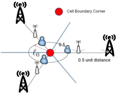
We demonstrate throughput enhancement via simulations with the proposed CoMP AF BF methods in a multi-cell network. The effectiveness of the proposed robust CoMP AF BF algorithms are compared with the non-robust ones from the perspectives of power consumption and the feasibility of the beamformers. A system topology for a subnetwork of N = 3 is illustrated in Fig. 7.1. To model and investigate the effects of pathloss, the SSs are set to move altogether along the directions to their corresponding BSs in simulations. As shown in Fig. 7.1, the distance between BS and SS is defined as a unit distance, when SS is located at cell boundary corner. The distance from the SSs to the
corner is denoted by `0 (unit distances). The channel variance σi,j2 between a transmit
node i and a receive node j is assumed as `−ni,j , where n is order of path loss and `i,j (unit
distances) denote the distance between the nodes i and j. Besides, for the conciseness of performance comparisons, all channels are considered to be block-faded. Namely, the channel coefficients remain unchanged within the period of a packet interval, and change randomly from packet to packet. A packet consists of 100 QPSK symbals.
For conciseness of presentation, the maximum number of ARQ rounds is limited to one in simulations as the improvement over two is not significant enough. In
con-Figure 7.1: An illustration for a subnetwork of 3 SSs.
trast, for CoMP ARQs without the assistance of relays, the BSs perform the CoMP retransmissions by themselves.
To compare the throughput performance subject to a total transmit power P0 for all
the active terminals, the design criterion for CoMP AF BF follows
max
Wr1,...,WrNmini SINR
(r)
i , s.t. Pr ≤ P0, ∀i (7.1)
According to [30], problems of maximizing the minimum SINR such as (7.1) are in-verse problems of power minimization problems such as SPMP-RS, by the strict mono-tonicity argument of the optimal solution of power minimization problems. The op-timal objective value of (7.1) can be efficiently found via the 1-dimensional bisection search [30]. Moreover, CoMP BS BF also follows the same criterion, max-min SINR subject to power constraints.
In our previous analysis, we just do not count in the effect of links between BSs and their non-associated RSs. To investigate the rationality of this relaxation, we just test max-min SINR CoMP AF BF under two types of simulation environment at one of which these effects are relaxed and at the other the effect of all links exists. As shown in Fig.
10 12 14 16 18 20 22 24 26 28 30 0 0.2 0.4 0.6 0.8 1 1.2 1.4 1.6 1.8 2 (a)Transmitting Power(dB) Throughput(bits/Channel use Order=3
R−ARQ, Max−min BF, Ignore weak links R−ARQ, Max−min BF, ARQ w/o relay, Max−min BF
RS BS 10 12 14 16 18 20 22 24 26 28 30 0 0.2 0.4 0.6 0.8 1 1.2 1.4 1.6 1.8 2 (b)Transmitting Power(dB) Throughput(bits/Channel use Order=4
R−ARQ, Max−min BF, Ignore weak links R−ARQ, Max−min BF, ARQ w/o relay, Max−min BF
BS RS
(a) (b)
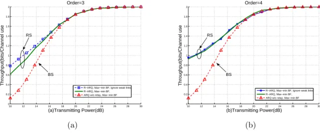
Figure 7.2: Simulated throughput when N=3 and `0 = 0: (a) Order of path loss=3 (b)
Order of path loss=4. The variance of channel between BSs and RSs and of AWGN noise are both assumed as one.
7.2, when order of path loss is four, the performance loss due to this relaxation seems to be trivial and the deployment of RSs are also shown to be yield more performance gain, which appears that our proposed BF design scheme yields a good tradeoff between performance and overhead and also that deployment of RSs especially effective for strong path loss environments.
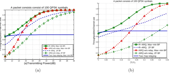
Fig. 7.3 (a) presents the throughput of different types of schemes versus the total
transmit power P0 when all the SSs are located at the boundary corner, namely, `0 = 0.
On the other hand, Fig. 7.3 (b) shows the effect of pathloss on throughput versus `0,
given P0 = 10 dB. In both figures, when the total transmit power P0 is low or when the
SSs are close to the boundary corner, the relay-assisted CoMP system outperforms the direct CoMP system without the assistance of relays even if the BF matrices are formed
simply based on the zero-forcing criterion. Moreover, when the total transmit power P0
is high or when the SSs are far away from the boundary corner, the relay-assisted CoMP system also outperforms the two-hop relaying. Besides, the beamformers designed based on the max-min SINR criterion (7.1) are apparently more effective than those designed based on the zero-forcing criterion.
10 12 14 16 18 20 22 24 26 28 30 0 0.2 0.4 0.6 0.8 1 1.2 1.4 1.6 1.8 2 (a)Transmitting Power(dB) Throughput(bits/Channel use
A packet consists consist of 100 QPSK symbals.
R−ARQ, Max−min BF, ARQ w/o relay, Max−min BF R−ARQ, ZF BF ARQ w/o relay, ZF BF Two−hop relaying, Max−min BF
0 0.05 0.1 0.15 0.2 0.25 0.3 0.35 0.4 0.45 0 0.2 0.4 0.6 0.8 1 1.2 1.4 1.6 1.8 2 (b)`0 Throughput(bits/Channel use
A packet consists of 100 QPSK symbals
R−ARQ, Max−min BF R−ARQ, ZF BF ARQ w/o relay, Max−min BF ARQ w/o relay, ZF BF Two−hop relaying
(a) (b)
Figure 7.3: Simulated throughput when N=3: (a) `0 = 0 (b) P0 = 10 dB.
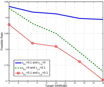
We demonstrate next the effectiveness of the robust CoMP AF BF designs. And the results are averaged over 1000 channel realizations. The SSs are evaluated at the
cell edge, i.e., `0 = 0. In addition, to assess the feasibility of CoMP AF relaying, a BF
scheme is considered infeasible for a certain channel realization if it can not ensure each SSs’ SINR requirement for any CSIs error within uncertainty region given 60 dB total transmission power budget; otherwise, it is called a feasible one.
On the other hand, to demonstrate the effectiveness of the robust BFs, non-robust CoMP BFs are also proposed for comparison. Unlike robust BF, non-robust ones just neglect the existence of channel quantization error or only consider the existence of
channel quantization error of some links. For clarity, considering ²r,s > 0 and ²b,r =
0, non-robust AF BFs are designed based on SPMP-RS rather than RSPMP-RS. In
addition, considering ²r,s > 0 and ²b,r > 0, non-robust AF BFs are designed based on
SPMP-RS or RSPMP-RS rather than GRSPMP-RS. However, these non-robust BFers are very likely fail to assure QoS and hence are then scaled up according to the procedure of tuning transmit power , which is summarized at Algorithm 2, for fair comparison of feasibility rate with the robust ones.