Bright and Efficient, Non-Doped, Phosphorescent Organic
Red-Light-Emitting Diodes**
By Yi-Hwa Song, Shi-Jay Yeh, Chin-Ti Chen,* Yun Chi,* Chao-Shiuan Liu, Jen-Kan Yu, Ya-Hui Hu,
Pi-Tai Chou,* Shie-Ming Peng, and Gene-Hsiang Lee
1. Introduction
Iridium metal complexes containing the 2-phenyl pyridine (ppy) type of chelating ligands have attracted much attention in recent years.[1] Preparing organic light-emitting devices (OLEDs) using emitters such as Ir(ppy)3and its derivatives, in which a strong spin±orbit coupling is induced by the heavy IrIII metal atom, effectively promotes intersystem crossing and pro-vides OLEDs with unprecedented electroluminescence (EL) efficiencies since both singlet and triplet excitons can decay radiatively.[2]Moreover, wavelength tunability over the entire visible spectrum has been achieved via systematically designing ancillary groups on the cyclometallated ligands.[3]As would be expected, success in the development of these light-emitting materials is essential for the realization of an efficient, full-col-or OLED display.
In order to optimize device efficiency up to a theoretical lim-it, it these heavy metal complex emitters have been doped into
a layer of charge-transporting host material comprised of 4,4¢-N,N¢-dicarbazole-biphenyl (CBP) or another host.[4] The remarkable enhancement in efficiency upon doping CBP was ascribed to its bipolar carrier transport, along with a favorable triplet energy level alignment between the host material and the IrIIIdopant, resulting in an increase of the energy-transfer efficiency. In addition, triplet±triplet (T±T) annihilation, which is a key adverse factor for phosphorescence-based emitters, can also be greatly inhibited by dispersing emitter molecules into the host matrix. This method has become a standard pro-tocol for phosphorescent emitters. In contrast, high-perfor-mance phosphorescent OLEDs fabricated by a much simpli-fied, non-doped method are rare and are mostly limited to short-wavelength (blue to yellow) emitters.[5,6] Long-wave-length orange or red OLEDs fabricated with non-doped, phos-phorescent host-emitters are rare and their typical perfor-mances are far from satisfactory.[6] Compared with doped phosphorescent OLEDs, their non-doped counterparts are neither bright in peak radiance (< 1000 cd m±2for orange and < 380 cd m±2 for red devices) nor effective in peak efficiency (< 3.5 cd A±1 for orange and < 2.3 cd A±1 for red devices).[6] Studies have also revealed that most of the red fluorescence emitters are composed of an extensively conjugated aromatic p-system, and hence should have a higher tendency to form a microcrystalline aggregate, resulting in rapid fluorescence quenching due to enhanced dipole±dipole interactions and/or p±p stacking interactions.[7]In this context, there should also be hardly any exceptions for the phosphorescent emitters. Herein, we report a new series of IrIIIcomplexes, with coordi-nation spheres consisting of two chelating phenyl substituted quinazoline and one (2-pyridyl) pyrazolate entity, which prove to serve as promising, non-doped, red phosphorescent host-emitters with relatively high efficiencies. Comprehensive struc-tural characterization and photophysical properties have also
±
[*] Dr. C.-T. Chen, S.-J. Yeh
Institute of Chemistry, Academia Sinica Taipei, 11 529 (Taiwan, ROC)
E-mail: [email protected] Prof. Y. Chi, Y.-H. Song, Prof. C.-S. Liu
Department of Chemistry, National Tsing Hua University Hsinchu, 300 (Taiwan, ROC)
E-mail: [email protected]
Prof. P.-T. Chou, J.-K. Yu, Y.-H. Hu, Prof. S.-M. Peng, G.-H. Lee Department of Chemistry and Instrumentation Center National Taiwan University
Taipei, 106 (Taiwan, ROC) E-mail: [email protected]
[**] This work was supported by the National Science Council of the Republic of China. We thank Prof. Yu-Tai Tao for instruction in the fabrication and measurement of OLEDs.
Ir(III)metal complexes with formula [(nazo)
2Ir(Fppz)](1), [(nazo)2Ir(Bppz)](2), and [(nazo)2Ir(Fptz)](3) [(nazo)H = 4-phenyl quinazoline, (Fppz)H = trifluoromethyl-5-(2-pyridyl) pyrazole, (Bppz)H = t-butyl-5-(2-pyridyl) pyrazole, and (Fptz)H = 3-trifluoromethyl-5-(2-pyridyl) triazole]were synthesized, among which the exact configuration of 1 was confirmed using single-crystal X-ray diffraction analysis. These complexes exhibited bright red phosphorescence with relatively short lifetimes of 0.4± 1.05 ls in both solution and the solid-state at room temperature. Non-doped organic light-emitting diodes (OLEDs) were fabri-cated using complexes 1 and 2 in the absence of a host matrix. Saturated red electroluminescence was observed at kmax= 626 nm (host-emitter complex 1) and 652 nm (host-emitter complex 2), which corresponds to coordinates (0.66,0.34) and (0.69,0.31), respectively, on the 1931 Commission Internationale de l'Eclairage (CIE) chromaticity diagram. The non-doped devices employing complex 1 showed electroluminance as high as 5780 cd m±2, an external quantum efficiency of 5.5 % at 8 V, and a current density of 20 mA cm±2. The short phosphorescence lifetime of 1 in the solid state, coupled with its modest p±p stacking interactions, appear to be the determining factors for its unusual success as a non-doped host-emitter.
P
been conducted in an attempt to unveil the key factors in the success of this unconventional phosphorescent host-emitter.
2. Results and Discussion
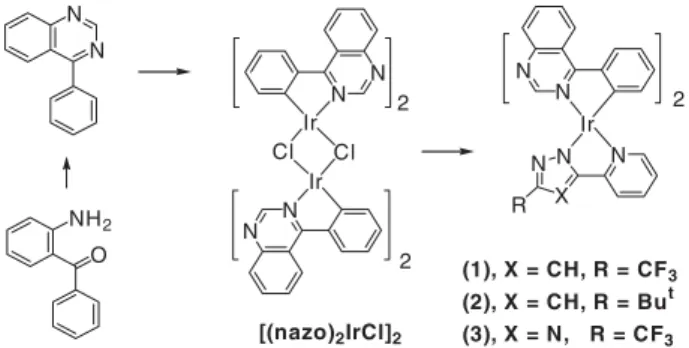
2.1. Synthesis
A synthetic pathway leading to the desired Ir complexes is depicted in Scheme 1. First of all, a 4-phenyl substituted quina-zoline ligand, (nazo)H, was obtained from the condensation reaction of 2-aminobenzophenone and formamide, according to the literature method.[8] The subsequent reaction of the (nazo)H ligand with IrCl3´nH2O in refluxing methoxyethanol
afforded the chloride-bridged dimer complex [(nazo)2IrCl]2in a high yield. This dimer complex reacted easily with the pyra-zole or triapyra-zole ligand to afford the emissive monomeric com-plexes of formula [(nazo)2Ir(Fppz)](1), [(nazo)2Ir(Bppz)](2), and [(nazo)2Ir(Fptz)](3), in the presence of Na2CO3, where (Fppz)H = 3-trifluoromethyl-5-(2-pyridyl) pyrazole, (Bppz)H = 3-t-butyl-5-(2-pyridyl) pyrazole, and (Fptz)H = 3-trifluoro-methyl-5-(2-pyridyl) triazole. These complexes were then characterized using routine methods. Complex 1 was further examined using single-crystal X-ray diffraction analysis to establish its exact configuration.
2.2. X-ray Crystal Structure
Complex 1, which consists of two cyclometal-lated phenyl quinazoline fragments and one (2-pyridyl) pyrazolate ligand has a distorted octa-hedral geometry around the iridium atom, as de-picted in Figure 1. The cyclometallated phenyl quinazoline ligands adopt an eclipsed orientation, and its spatial arrangement is akin to that ob-served for the chloride-bridged dimer complex [(ppy)2Ir(l-Cl)]2[9] and monomeric acetylaceto-nate (acac) complexes such as (ppy)2Ir(acac).[10] The pyrazolate chelate is located opposite to the cis-oriented carbon atoms, completing an octahe-dral arrangement. The quinazoline core skeleton
shows a large deformation with respect to the adjacent 4-phe-nyl substituent, for which the calculated plane-to-plane dihe-dral angles are 23.9/ and 29.4/. Obviously, this distortion is due to an unfavorable steric hindrance originating from the through-space repulsion between the two nearby ortho-hydro-gen atoms on C(15) and C(19) as well as on C(29) and C(33). A similar structure has been observed in the related isoquino-line system.[11] Nevertheless, the intermolecular packing dia-gram of 1 reveals several weak but notable intermolecular interactions (see Fig. 2) that possibly play a role in the radia-tionless quenching of the phosphorescent emission. First of all, one of the quinazoline ligands is nearly parallel to the pyridyl ring of the neighboring molecule. This is clearly shown by the rather short non-bonding contact of 3.31 between the C(3) atom of the unique pyridyl-pyrazolate ligand and the C(30) atom of the quinazoline ligand of the adjacent molecule (see Figs. 1 and 2 for atom labeling).
N N N N Ir N X N N R 2 2 (1), X = CH, R = CF 3 (2), X = CH, R = But (3), X = N, R = CF3 N N Ir N N Ir Cl Cl 2 O NH2 [(nazo)2IrCl]2
Scheme 1. Synthetic method leading to desired complexes.
Figure 1. ORTEP diagram of 1. Selected bond distances []: Ir± N(1) = 2.164(4), Ir±N(2) = 2.105(4), Ir±N(4) = 2.041(4), Ir±N(6) = 2.040(4), Ir±C(23) = 2.007(5), Ir±C(37) = 1.996(5) and angles [degrees]: N(1)±Ir± N(2) = 76.5(2), N(4)±Ir±C(23) = 79.1(2), N(6)±Ir±C(37) = 79.6(2).
Figure 2. Portion of the crystal-packing diagram of 1. The weak intermolecular non-bond-ing contacts are marked with dotted lines.
FULL
P
The second class of interaction may be attributed to the edge-to-face ring contact (3.09 ) between the H(26A) atom of one quinazoline ligand and the C(10) atom of the pyridyl-pyrazolate ligand of the adjacent molecule (Fig. 2). Similar short contacts (H(2A)_C(31) = 3.10 , H(2A)_C(32) = 3.08 , and H(7A)_C(20) = 3.03 ) were also found between the H(2A) and H(7A) atoms of the pyridyl-pyrazolate ligand and the adjacent phenyl quinazoline ligand. However, such inter-molecular interactions are unlikely to enhance the unwanted triplet±triplet annihilation, as the energy level of the pyrazolate fragment is too high to interfere with the normal emission from the3MLCT or the corresponding3p±p* state localized on the quinazoline ligand.[12]All together, a detailed structural analy-sis shows a moderate p±p stacking for 1 in the crystal, which is expected to have an adverse effect for making a host-emitter. In contrast, however, a highly efficient host-emitter has been fabricated for 1, indicating that other factors must predominate in the device performance (see below).
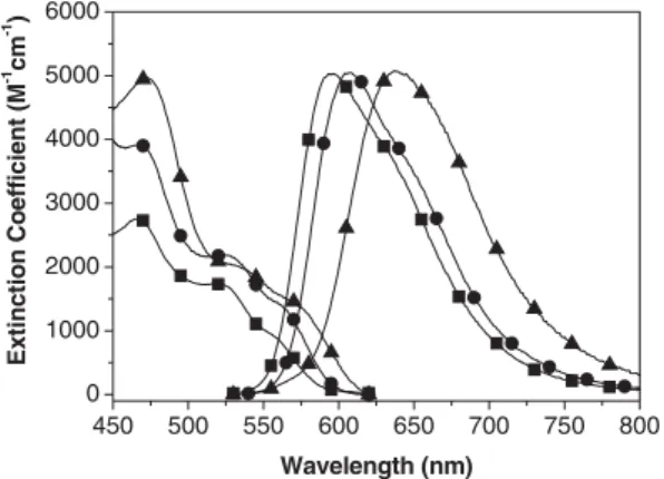
2.3. Photophysical Characterization of the Phosphorescence Figure 3 shows the UV-vis absorption and emission spectra of complexes 1±3 in CH2Cl2at 298 K. All three complexes pos-sess similar spectral features, in which the two lower-lying
bands that appear in the region of » 500±625 nm, as supported by their extinction coefficients of £ 3000 M±1cm±1, are tenta-tively assigned to the1MLCT and3MLCT transitions. The close absorptivity between these two bands, e.g., e = 2150 and 1330 M±1cm±1at peak wavelengths of 525 and 565 nm, respec-tively for 1, suggests that the S0®3MLCT transition is greatly enhanced and becomes partially allowed due to strong spin±or-bit coupling. Complex 1 exhispin±or-bits an intense emission with a maximum at 607 nm (U = 0.52) and a lifetime as short as 1.05 ls in degassed CH2Cl2. An oxygen quenching rate of » 1.78109M±1s±1for the emission in CH
2Cl2, together with its spectral overlap with respect to the3MLCT absorption profile, leads us to conclude that the emission originates from a triplet manifold.
The phosphorescence peak wavelength can be fine-tuned by replacing the auxiliary group. Substituting the CF3in 1 with the electron-donating t-butyl group, yielding complex 2, gives rise to a bathochromic spectral shift due to the destabilization of the d-orbital in the central IrIIIatom. Conversely, the (2-pyri-dyl) triazolate in 3 serves as a stronger electron-withdrawing ligand, stabilizing the d-orbital and giving rise to an emission » 10 nm hypsochromically shifted relative to that of 1. In the solid crystal, the emission spectra of both 1 and 3 are batho-chromically shifted relative to the solution spectra. This phe-nomenon is generally attributed to p±p stacking between ligand chromophores; such packing has been observed in the crystal structure of 1. On the other hand, as indicated by the small shift in wavelength (see Table 1), the p±p stacking of 2 is supposed to be less significant. We assume that an increase in the steric hindrance via the introduction of a bulky t-butyl group in 2 reduces the stacking effect drastically, resulting in a spectral resemblance between the solution and solid phases. Detailed photoluminescent and dynamical properties for com-plexes 1±3 are listed in Table 1.
2.4. OLED Characterization
Considering the long-wavelength emission required for red phosphors, both complexes 1 and 2 were chosen for the fabri-cation of OLED devices (Table 2). Of particular note is that devices I±III became brighter and more efficient as the doping level of 1 was increased from » 7±21 %. To our knowledge, this is in contrast to most literature reports, in which an upper limit of the doping level of » 10 % is given, except for the case where the pinene group was introduced to suppress aggregation quenching.[13] The unexpected success at high doping levels prompted us to adopt a non-doped, host-emitting approach in the fabrication of the fourth device (IV in Table 2). Whereas devices I±III showed unsatisfactory orange±red EL, device IV clearly showed a deep-red EL with kmaxat 626 nm (Fig. 4) cor-responding to (0.66,0.34) of the 1931 Commission Internatio-nale de l'Eclairage (CIE) chromaticity (Table 2).
The performance of this authentic red, non-doped OLED is remarkable, considering that a sufficient luminance
450 500 550 600 650 700 750 800 0 1000 2000 3000 4000 5000 6000 Ex tinction Co efficient (M -1 cm -1 ) Wavelength (nm)
Figure 3. UV-vis absorption and normalized emission spectra of 1 (d), 2 (~), and 3 (j) i n CH2Cl2at 298 K. Note that the emission spectra were acquired under degassed conditions.
Table 1. Photophysical properties of complexes 1±3.
Complex kabs max
[nm]
e
[M±1cm±1] PL k[nm]max[a] degassedU [a] s [a][ls]
1 565 1330 607 (634) 0.52 1.05 525 2150 (0.41) (0.40) 470 3970 2 575 1369 638 (638) 0.27 0.92 530 2120 (0.17) (0.24) 475 4670 3 556 933 596 (625) 0.61 1.11 523 1720 (0.32) (0.35) 468 2670
[a] In CH2Cl2. Data in parentheses refer to the solid state.
P
(1330 cd m±2) and good efficiency (6.3 %, 6.7 cd A±1, or 2.5 lm W±1) were successfully achieved at a practical current density of 20 mA cm±2. Based on the same protocol, another red OLED, containing phosphor 2 (device VIII in Table 2), was also fabricated; this showed an even further red-shifted EL with kmaxat 652 nm, corresponding to (0.69,0.31) CIE coordi-nates. The brightness and efficiency of device VIII were mod-erately reduced, and the turn-on voltage was relatively higher than those of device IV (see Fig. 4). In addition to the reason of low quantum efficiency, a smaller bandgap (higher energy level of highest occupied molecular orbital (HOMO) or lower energy level of lowest occupied molecular orbital (LUMO)), and hence a stronger charge trap of 2 may be the cause for the different performances. The results here successfully demon-strate unusual phosphorescence-based red OLEDs fabricated using a non-doped architecture, and the devices were bright and efficient.[6] Moreover, in comparison with other red OLEDs based on Ir-complex dopants,[14]devices I±IV suffered less from a decay in efficiency at an elevated current density (Fig. 4). In particular, it is noteworthy that the non-doped devi-ce VIII showed quite a stable efficiency over a wide range of current density, up to 500 mA cm±2. Such an extraordinary per-formance can be attributed to the relatively short emission life-times of complexes 1 and 2.
3. Conclusion
We have demonstrated the synthesis of novel, red-emitting IrIIIcomplexes based on the 4-phenyl quinazoline and (2-pyri-dyl) pyrazole ligands. In contrast to most other IrIII emitters, this new series of complexes can be fabricated using a non-doped OLED structure, even though p±p stacking among the ligand chromophores is obviously present between neighboring molecules, as revealed by X-ray structure analysis. Moreover, the complexes in this series have high phosphorescence yields
Table 2. EL characteristics of OLEDs (devices I±VIII) fabricated using com-plex 1 or 2.
Device [a]
Max. luminance
[cd m±2] [b] Efficiency[%] [c] [%, cd AMax. efficiency±1, lm W±1] EL k[nm]max CIE[x,y]
I 58 570 6.8 (12) 8.0, 16.4, 5.9 600 0.59, 0.39 (14 010, 3160) 7.7 (10) II 45 200 7.1 (12) 8.1, 14.0, 4.9 606 0.62, 0.37 (12 370, 2840) 8.1 (10) III 38 180 7.3 (12) 8.8, 14.5, 5.0 610 0.63, 0.37 (11 990, 2870) 8.7 (10) IV 29 790 5.5 (10) 6.3, 6.7, 2.7 626 0.66, 0.34 (5780, 1330) 6.3 (8) V 39 260 7.3 (12) 8.1, 13.0, 4.1 618 0.62, 0.34 (11 560, 2590) 8.1 (10) VI 40 410 6.3 (12) 7.6, 11.2, 4.4 622 0.63, 0.34 (9360, 2190) 7.4 (9) VII 31 450 5.2 (11) 5.2, 7.3, 2.2 622 0.63, 0.34 (7283, 878) 3.1 (8) VIII 6381 2.5 (11) 2.7, 1.4, 0.4 652 0.69, 0.31 (1272, 270) 2.6 (10)
[a] Devices I±IV: ITO/NPB(40 nm)/1:CBP(x %, 30 nm)/BCP (10 nm)/Alq3 (30 nm)/Mg:Ag, x = 7, 14, 21, 100 %, respectively. Devices V±VIII: ITO/ NPB(40 nm)/2:CBP(x%, 30 nm)/BCP (10 nm)/Alq3(30 nm)/Mg:Ag, x = 7, 14, 21, 100 %, respectively. [b] Numbers in parentheses are the electrolu-minance at current densities of 100 and 20 mA cm±2. [c] External quantum efficiency at current densities of 100 and 20 mA cm±2. Numbers in par-entheses are the corresponding voltage.
300 400 500 600 700 800 0.0 0.5 1.0 Device VIII Device IV Device III Device II Device I E L Inten s ity (A .U.) Wavelength (nm) 0 2 4 6 8 10 12 14 16 1 10 100 1000 10000 100000 Device I Device II Device III Device IV Device VIII El ectr ol uminance (cd/ m 2 ) Voltage (V) 0 100 200 300 400 500 0 2 4 6 8 10 Device VIII Device IV Device I Device II Device III E x te rn al Q u an tum E ffic ien c y (% )
Current Density (mA/cm2) a)
b)
c)
Figure 4. EL spectra (a), voltage dependency of electroluminescence (b), and current-density dependency of external quantum efficiency (c) of OLED devices I, II, III, IV, and VIII.
FULL
P
(see Table 1) with relatively short lifetimes of < 1 ls, which are significantly shorter than those of other known red phosphor-escence emitters, such as platinum octaethylporphyrin (Pt(OEP)) (»50 ls), Ir(btp)2(acac) (4 ls),[15]and Ir(piq)2(acac) (1.7 ls),[14] and comparable with that of the best performing Ir(tiq)3and Ir(fliq)3(0.74 ls) complexes (btp: 2-(2¢-benzo[4,5-a]thienyl)pyridinato; piq: 1-(phenyl)isoquinolinato; tiq: 1-thio-phen-2-ylisoquinolinato; fliq: 1-(9,9-dimethyl-9H-fluoren-2-yl)isoquinolinato).[11] We believe that the short radiative lifetime is pivotal for rationalizing the unusually strong phos-phorescence from this simplified device structure. Our finding is of particular importance for fabricating devices with a much simpler, more cost-effective architecture. Based on a similar argument, this non-doped device architecture should be equally applicable to other phosphorescent emitters, so long as the guest emitters possess a similar degree of intermolecular p±p stacking as well as an extraordinarily short radiative life-time in the solid state. Focus on generalizing this proposed mechanism via the design and synthesis of other phosphores-cent host-emitter materials is currently in progress.
4. Experimental
General Information: All reactions were performed under nitrogen. Solvents were distilled from an appropriate drying agent prior to use. Commercially available reagents were used without further purifi-cation. Mass spectra were obtained on a JEOL SX-102A instrument operating in electron impact (EI) mode or fast atom bombardment (FAB) mode. 1H and 13C NMR spectra were recorded on Varian Mercury-400 or INOVA-500 instruments.
CyclometallatedIrIII Dimer: The chloride-bridged IrIII dimer com-plex with formula [(nazo)2IrCl]2 was synthesized according to the method reported by Nonoyama [16], which involving refluxing IrCl3´ nH2O (3.02 g, 8.5 mmol) with 4-phenylquinazoline (nazo)H (4.04 g, 19.6 mmol) in a mixture of 2-methoxyethanol (30 mL) and water (10 mL) for 24 h. The red product (4.98 g, 3.9 mmol, 92 %) was isolated by filtration, washed with cold acetone, and dried under vacuum. Spectral Data: 1H NMR (500 MHz, CDCl 3, 294 K) d [ppm]: 9.58 (s, 4H, CH), 8.89 (d, J = 8.5 Hz, 4H, CH), 8.26 (d, J = 8.0 Hz, 4H, CH), » 8.07±8.02 (m, 8H, CH), » 7.86±7.83 (m, 4H, CH), 6.88 (t, J = 7.3 Hz, 4H, CH), 6.59 (t, J = 7.3 Hz, 4H, CH), 6.13 (d, J = 8.0 Hz, 4H, CH).
Preparation of [(nazo)2Ir(Fppz)]: To a 100 mL flask was added [(nazo)2IrCl]2 (1.04 g, 0.815 mmol), 3-trifluoromethyl-5-(2-pyridyl) pyrazole (FppzH, 0.42 g, 1.97 mmol), Na2CO3(0.86 g, 8.15 mmol), and 2-ethoxyethanol (40 mL), and the mixture was then heated to reflux for 8 h. Excess water was added after cooling the solution to room temperature. The resulting precipitate was collected by filtration and washed with diethyl ether. Further purification was conducted using silica gel column chromatography using CH2Cl2as the eluent, giving 1.16 g of red±orange solid (1, 1.42 mmol, 87 %). A single crystal suit-able for X-ray diffraction was obtained from a layered solution of methanol and CH2Cl2.
Spectral Data of 1: MS (EI), m/z = 815, M+.1H NMR (500 MHz, CDCl3, 294 K) d [ppm]: 8.97 (d, J = 8.5 Hz, 1H, CH), 8.83 (d, J = 8.5 Hz, 1H, CH), 8.45 (d, J = 8.0 Hz, 1H, CH), 8.36 (d, J = 8.0 Hz, 1H, CH), 8.32 (s, 1H, CH), 8.22 (s, 1H, CH), 8.08 (d, J = 7.5 Hz, 1H, CH), 8.03 (d, J = 8.5 Hz, 1H, CH), » 7.93±7.88 (m, 3H, CH), » 7.82±7.77 (m, 3H, CH), 7.58 (d, J = 5.5 Hz, 1H, CH), » 7.14±7.09 (m, 4H, CH), 6.95 (t, J = 7.0 Hz, 1H, CH), 6.86 (t, J = 7.0 Hz, 1H, CH), 6.51 (d, J = 7.5 Hz, 1H, CH), 6.44 (d, J = 7.0 Hz, 1H, CH).19F NMR (470 MHz, CDCl 3)
d [ppm]: ±60.0 (s). Anal. calcd. for C37H23F3IrN7: N, 12.03; C, 54.54; H, 2.85. Found: N, 11.91; C, 54.22; H, 3.23.
X-ray Structural Analysis: Single crystal X-ray diffraction data were measured on a Bruker Smart charge-coupled device (CCD) diffrac-tometer using k(Mo Ka) radiation (k = 0.71073 ). The data collection was executed using the SMART program. Cell refinement and data reduction were made with the SAINT program. The structure was determined using the SHELXTL/PC program and refined using full-matrix least squares. All non-hydrogen atoms were refined aniso-tropically, whereas hydrogen atoms were placed at the calculated posi-tions and included in the final stage of refinements with fixed parame-ters.
SelectedCrystal Data of 1: C37H23F3N7Ir´CH4O, M = 846.87, mono-clinic, space group P21/n, a = 14.5269(7), b = 13.2230(6), c = 17.0248(8) , b = 94.9691(11) , V = 3258.0(3) 3, Z = 4, r
alcdc= 1.727 g cm±1, F(000) =
1664, crystal size = 0.40 « 0.03 « 0.02 mm, k(Mo Ka) = 0.7107 , T = 295(2) K, l = 4.159 mm±1, 7475 reflections collected (R
int= 0.0606), final R1[I > 2r(I)]= 0.0376, and wR2(all data) = 0.0873. The crystallo-graphic data of this complex (excluding structure factors) have been deposited at the Cambridge Crystallographic Data Centre with the allocated deposition number CCDC-238210.
Preparation of [(nazo)2Ir(Bppz)]: A mixture of [(nazo)2IrCl]2 (1.00 g, 0.784 mmol), 3-t-butyl-5-(2-pyridyl) pyrazole (BppzH, 0.40 g, 1.96 mmol), Na2CO3 (0.82 g, 7.74 mmol), and 2-ethoxyethanol (40 mL) was heated to reflux for 8 h. Excess water was added after cooling the solution to room temperature. The resulting precipitate was collected by filtration and washed with diethyl ether. Further purifica-tion was conducted by direct vacuum sublimapurifica-tion (280 C, 160 mtorr), giving 1.00 g of dark-red solid (2, 1.25 mmol, 79 %).
Spectral Data of 2: MS (FAB), m/z 804, (M + 1)+. 1H NMR (400 MHz, CDCl3, 294 K) d [ppm]: 8.96 (d, J = 8.8 Hz, 1H, CH), 8.82 (d, J = 8.8 Hz, 1H, CH), 8.46 (d, J = 8.0 Hz, 1H, CH), 8.33 (d, J = 8.0 Hz, 1H, CH), 8.28 (s, 1H, CH), 8.18 (s, 1H, CH), 8.06 (d, J = 8.4 Hz, 1H, CH), 8.01 (d, J = 8.4 Hz, 1H, CH), » 7.91±7.85 (m, 2H, CH), » 7.83±7.70 (m, 4H, CH), 7.50 (d, J = 5.2 Hz, 1H, CH), 7.14 (t, J = 8.0 Hz, 1H, CH), 7.09 (t, J = 8.0 Hz, 1H, CH), »6.95±6.90 (m, 3H, CH), 6.57 (s, 1H, CH), 6.51 (t, J = 7.6 Hz, 2H, CH), 1.26 (s, 9H, CMe3). Anal. calcd. for C40H32IrN7: N, 12.21; C, 59.83; H, 4.02. Found: N, 12.15; C, 59.56; H, 4.23.
Preparation of [(nazo)2Ir(Fptz)]: To a 100 mL flask was added [(nazo)2IrCl]2 (0.20 g, 0.157 mmol), 3-trifluoromethyl-5-(2-pyridyl) triazole (FptzH, 0.08 g, 0.392 mmol), Na2CO3(0.17 g, 1.57 mmol), and 2-ethoxyethanol (40 mL), and the mixture was then heated to reflux for 9 h. Excess water was added after cooling the solution to room temperature. The resulting precipitate was collected by filtration and washed with diethyl ether. Further purification was conducted using silica gel column chromatography using CH2Cl2as the eluent, giving 210 mg of orange solid (3, 0.260 mmol, 82 %).
Spectral Data of 3: MS (FAB), m/z 817, (M + 1)+. 1H NMR (500 MHz, CDCl3, 294 K) d [ppm]: 8.88 (d, J = 8.5 Hz, 1H, CH), 8.84 (d, J = 8.5 Hz, 1H, CH), 8.47 (s, 1H, CH), 8.38 (dd, J = 9.0 Hz, 5.5 Hz, 2H, CH), 8.31 (d, J = 7.5 Hz, 1H, CH), 8.21 (s, 1H, CH), 8.08 (d, J = 8.0 Hz, 1H, CH), 8.02 (d, J = 9.0 Hz, 1H, CH), » 7.92±7.87 (m, 2H, CH), » 7.86±7.82 (m, 1H, CH), »7.79±7.75 (m, 2H, CH), 7.57 (d, J = 5.5 Hz, 1H, CH), »7.15±7.11 (m, 2H, CH), 7.46 (t, J = 7.0 Hz, 1H, CH), 6.96 (t, J = 7.0 Hz, 1H, CH), 6.86 (t, J = 7.0 Hz, 1H, CH), 6.57 (d, J = 8.0 Hz, 1H, CH), 6.47 (d, J = 8.0 Hz, 1H, CH) Anal. calcd. for C36H22F3IrN8: N, 13.74; C, 53.00; H, 2.72 Found: N, 13.60; C, 53.21; H, 2.91.
Spectroscopic andDynamic Measurements: Steady-state absorption and emission spectra were recorded using a Hitachi (U-3310) spectro-photometer and an Edinburgh (FS920) fluorimeter, respectively. A configuration of front-face excitation was used to measure the emission of the solid sample, in which the cell was made by assembling two edge-polished quartz plates with various Teflon spacers. Lifetime studies were performed using an Edinburgh FL 900 photon-counting system with a hydrogen-filled/or a nitrogen lamp as the excitation source. An integrating sphere (Labsphere) was applied to measure the quantum yield in the solid state, in which the solid sample film was prepared via the vapor-deposition method and was excited by a 514 nm Ar+laser line. The resulting luminescence was acquired by an inten-sified charge-coupled detector for subsequent quantum yield analyses.
P
OLED Fabrication andMeasurement: The fabrication of OLEDs was conducted using high-vacuum (10±6torr) thermal evaporation of the material onto pre-cleaned indium tin oxide (ITO)-coated glass substrates (sheet resistance £ 50 X/sq). NPB, CBP, BCP, and Alq3 are abbreviations for 1,4-bis(1-naphylphenylamino) biphenyl, 1,4-bis(N-carbazolyl) biphenyl, 1,4-bis(1-naphylphenylamino) biphe-nyl, 2,9-dimethyl-4,7-diphenyl-1,10-phenanthroline, and tris(8-hydroxy-quinoline) aluminum, respectively. EL characteristics, including electroluminance [cd m±2], current density [mA cm±2], driving voltage [V], and EL quantum efficiency [%], [cd A±1], and [lm W±1], were recorded using literature methods [17].
Received: March 31, 2004 Final version: May 14, 2004
±
[1]a) M. A. Baldo, D. F. O'Brien, Y. You, A. Shoustikov, S. Sibley, M. E. Thompson, S. R. Forrest, Nature 1998, 395, 151. b) M. K. Nazeerud-din, R. Humphry-Baker, D. Berner, S. Rivier, L. Zuppiroli, M. Graet-zel, J. Am. Chem. Soc. 2003, 125, 8790. c) A. J. Middleton, W. J. Marshall, N. S. Radu, J. Am. Chem. Soc. 2003, 125, 880. d) X. Gong, J. C. Ostrowski, G. C. Bazan, D. Moses, A. J. Heeger, M. S. Liu, A. K.-Y. Jen, Adv. Mater. 2003, 15, 45.
[2]a) B. Carlson, G. D. Phelan, W. Kaminsky, L. Dalton, X. Z. Jiang, S. Liu, A. K.-Y. Jen, J. Am. Chem. Soc. 2002, 124, 14 162. b) J. C. Ostrowski, M. R. Robinson, A. J. Heeger, G. C. Bazan, Chem. Commun. 2002, 784. c) J.-P. Duan, P.-P. Sun, C.-H. Cheng, Adv. Mater. 2003, 15, 224. d) T. Tsuzuki, N. Shirasawa, T. Suzuki, S. Tokito, Adv. Mater. 2003, 15, 1455.
[3]a) V. V. Grushin, N. Herron, D. D. Le Cloux, W. J. Marshall, V. A. Petrov, Y. Wang, Chem. Commun. 2001, 1494. b) A. B. Tamayo, B. D. Alleyne, P. I. Djurovich, S. Lamansky, I. Tsyba, N. N. Ho, R. Bau, M. E. Thompson, J. Am. Chem. Soc. 2003, 125, 7377.
[4]a) H. Kanai, Ichinosawa, Y. Sato, Synth. Met. 1997, 91, 195. b) C. Ada-chi, R. Kwong, S. R. Forrest, Org. Electron. 2001, 2, 37. c) S. Lamans-ky, P. I. Djurovich, F. Abdel-Razzaq, S. Garon, D. L. Murphy, M. E. Thompson, J. Appl. Phys. 2002, 92, 1570. d) S. Tokito, T. Iijima,
Y. Suzuri, H. Kita, T. Tsuzuki, F. Sato, Appl. Phys. Lett. 2003, 83, 569. [5]a) Y. Wang, N. Herron, V. V. Grushin, D. Le Cloux, V. Petrov, Appl.
Phys. Lett. 2001, 79, 449. b) R. J. Holmes, B. W. D'Andrade, S. R. Forrest, X. Ren, J. Li, M. E. Thompson, Appl. Phys. Lett. 2003, 83, 3818.
[6]V. Grushin, D. D. Lecloux, V. A. Petrov, Y. Wang, US Patent 6 670 645, 2003.
[7]a) H.-C. Yeh, L.-H. Chan, W.-C. Wu, C.-T. Chen, J. Mater. Chem. 2004, 14, 1240. b) K. R. J. Thomas, J. T. Lin, M. Velusamy, Y.-T. Tao, C.-H. Chuen, Adv. Funct. Mater. 2004, 14, 83. c) H.-C. Yeh, S.-J. Yeh, C.-T. Chen, Chem. Commun. 2003, 2632. d) W.-C. Wu, H.-C. Yeh, L.-H. Chan, C.-T. Chen, Adv. Mater. 2002, 14, 1072. e) K. R. Justin Thomas, J. T. Lin, Y.-T. Tao, C.-H. Chuen, Adv. Mater. 2002, 14, 822. [8]B. C. Uff, B. L. Joshi, F. D. Popp, J. Chem. Soc., Perkin Trans. 1 1986,
2295.
[9]F. O. Graces, K. A. King, R. J. Watts, Inorg. Chem. 1988, 27, 3464. [10]a) S. Lamansky, P. Djurovich, D. Murphy, F. Abdel-Razzaq, R. Kwong,
I. Tsyba, M. Bortz, B. Mui, R. Bau, M. E. Thompson, Inorg. Chem. 2001, 40, 1704. b) S. Lamansky, P. Djurovich, D. Murphy, F. Abdel-Razzaq, H.-E. Lee, C. Adachi, P. E. Burrows, S. R. Forrest, M. E. Thompson, J. Am. Chem. Soc. 2001, 123, 4304.
[11]A. Tsuboyama, H. Iwawaki, M. Furugori, T. Mukaide, J. Kamatani, S. Igawa, T. Moriyama, S. Miura, T. Takiguchi, S. Okada, M. Hoshino, K. Ueno, J. Am. Chem. Soc. 2003, 125, 12 971.
[12]P.-C. Wu, J.-K. Yu, Y.-H. Song, Y. Chi, P. -T. Chou, S.-M. Peng, G.-H. Lee, Organometallics 2003, 22, 4938.
[13]H. Z. Xie, M. W. Liu, O. Y. Wang, X. H. Zhang, C. S. Lee, L. S. Hung, S. T. Lee, P. F. Teng, H. L. Kwong, H. Zheng, C. M. Che, Adv. Mater. 2001, 13, 1245.
[14]Y.-J. Su, H.-L. Huang, C.-L. Li, C.-H. Chien, Y.-T. Tao, P.-T. Chou, S. Datta, R.-S. Liu, Adv. Mater. 2003, 15, 884.
[15]M. Adachi, A. Baldo, S. R. Forrest, S. Lamanky, M. Thompson, R. C. Kwong, Appl. Phys. Lett. 2001, 78, 1622.
[16]M. Nonoyama, J. Organomet. Chem. 1975, 86, 263.
[17]L.-H. Chan, R.-H. Lee, C.-F. Hsieh, H.-C. Yeh, C.-T. Chen, J. Am. Chem. Soc. 2002, 124, 6469.