Cascadable current-mode filters using
single FTFN
Shen-Iuan Liu
Indexing terms: Current-mode circuits, Filters
A new configuration for realising current-mode filters using a single four-terminal floating nullor (FTFN) is presented. It can realise lowpass, bandpass, highpass, notch and allpass filters from the same configuration. This configuration has a high output impedance, so the synthesised current-mode filters can be cascaded without additional buffers. Moreover, the resultant current-mode filters will be insensitive to the current tracking error of an FTFN. Experimental results that confirm the
theoretical analyses are obtained.
Introduction: Current-mode circuits have been receiving significant attention as they have the potential advantages of accuracy and wide bandwidth over their voltage-mode counterparts [I]. Poten- tially, there is one limitation in most current-mode circuits. They need additional current buffers to cascade the similar stages or to extract the output current. Therefore, several cascadable current- mode filters [2 - 61 using second-generation current conveyors
(CCIIs) and a single four-terminal floating nullor (FTFN) [7 ~ 91 have been developed. However, there is no configuration using a single FTFN, which can realise various types of cascadable cur- rent-mode filters. In this Letter, such a new configuration is pre- sented. Experimental results which confirm the theoretical analysis are obtained.
y ! T i & T z
,
w
"2 12=0--- - - > '02 1730111 XFig. 1 Nullor model of FTFN
Circuit description: The port relations of an FTFN, shown in Fig. 1 , can be characterised as I , = I2 = 0, VI = Vz and
Iol
= I,, [7 - 91.Considering the proposed configuration in Fig. 2, its transfer func- tion can be derived as
If y , = 0 (open circuit) and y,iy3 - ysiyl (i.e. z, = z,(l
+
z,iz,)), eqn.1 can be simplified as
( 2 )
I o - Ys - Y 2
I%, Y4 + Y 2
A first-order allpass filter can be obtained if y , = UR,, y, = sC, y4 = y, = liR and y , = li(R,
+
R).If y , = 0, yl = y , and y , = ys, eqn. 1 can be simplified as
( 3 )
I o - 2Y3 - Y2
Im Y2
-~ -
Furthermore, if y , = sC,
+
liR, and y 3 = l / ( R ,+
list,), eqn. 3 will be I , - I,, s2C2C3R2R3+
s ( C ~ R ~+
C3R3 - 2C3Rz)+
1 s2C2C3R2R3+
s ( C ~ R ~+
C3R3)+
1 (4)Hence, if C,R, + C,R, = 2C,R,, a second-order notch filter can be realised. If C,R,
+
C,R, = C,R,, a second-order allpass filter can be achieved.If y s = 0 and y4iy, = y,/y,, eqn. 1 can be simplified as
( 5 )
I o - Y5Y2
I m
- -
Y4Y1
+
YSYl - Y2Y5Furthermore, if y , = sC,
+
UR,, y , =se,,
y 3 = UR,, y , = liR,, y 5 = sC, and C2R, = CsR,, eqn. 5 can be expressed asIo
-
s2CzC~R1R4- _
It,
s2(C1-
C2)CSR1Rq+
s(ClR1+
C5R4)+
1 ( 6 ) Thus, if C, > C,, a second-order highpass filter can be obtained.If y I = sC,
+
IiR,, y2 = UR2, y , = se,, y, = SC,, y , = 1/R, andC,R, = C,R,, eqn. 5 can be expressed as 1 s2C1C4R2Rs
+
s ( C 4 V+
CiR2)+
(2
- 1) I , - - - Im (7)Thus, if R, > R,, a second-order lowpass filter can be obtained.
[in
1
m
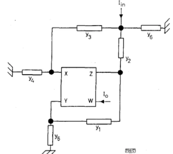
Fig. 2 Configuration for realising current-mode filters with high output impedance
To realise a bandpass filter, the admittances might be chosen as follows: y , = sC,
+
UR,, y , = y , = y, = l/R2, and y4 = y , =se,.
eqn. 1 can be expressed as
( 8 )
I o - - SC4lR2
-
I,, S23CIC4
+
s(&+
3. - G )+
1 R I R2 Rz R1RzThe natural frequency and quality factor of this bandpass filter can be expressed as
Taking into account the nonideal FTFN, namely I,, = aI,, and V, = PV,, where CL = 1 - el, (e, << 1 ) denotes the current track- ing error of an FTFN and
p
= 1 - E,, E~ (&* << 1 ) is the input volt- age tracking error, since the current output of the FTFN in Fig. 1is directly connected to the load, the resultant current-mode filters will be insensitive to the current tracking error of an FTFN except for current gain.
R
.IIH~~
1730131
-
Fig. 3 Current-mode second-order bandpass filter
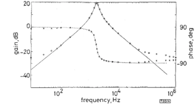
Experimental results: To demonstrate the feasibility of the pro- posed circuits, a current-mode bandpass filter derived from Fig. 1 is implemented as shown in Fig. 3 with C = lnF, R = 10 ki2 and RI = 270kC2. The FTFN consists of an operational amplifier (LF356) and bipolar transistors (CA3096AE) [6, 91. Fig. 4 shows the experimental results for a second-order bandpass filter in Fig. 3. Experimental results confirm with the results of the theoretical analysis.
certain planar arrays, to excite microstrip patch and dielectric res- onator antennas and to couple the energy between multilayer inte- grated circuits. Several rigorous numerical and approximate methods [I - 51 have been applied to analyse microstrip line fed printed slots, and results for a centre-fed slot perpendicular to a microstrip line have shown very high resonant radiation resistance. To realise the efficient impedance matching and to control the coupling, the slot may need to be inclined with a 190” angle to the microstrip line. However, most analyses reported so far are based on the assumption that the slot is perpendicular to the microstrip line, and few limited results were reported for an arbitrarily inclined slot [6].
The purpose of this Letter is to present a new general analysis of an arbitrarily inclined slot on the ground plane of a microstrip line. The spectral domain approach is used to obtain propagation characteristics of the fundamental mode of the microstrip line and the fields generated by the slot. The reciprocity theorem is applied to derive the reflection and transmission coefficients, from which the components of an equivalent slot circuit are found.
0
L
... I . ~ . * . ~ .../’p
-.-401
1
o2
1o4
1 06frequency, Hz 17301LI
Fig. 4 Comparisons between theoretical and experimental results f o r bandpass filter in Fig. 3 with C = lnF, R = I0k.Q and R, = 270ki2 Theory: ~ gain, - - - - phase
Experiment: 0 gain, X phase
Conclusions: A new configuration with single FTFN for realising various types of cascadable current-mode filters is presented. Sec- ond-order lowpass, bandpass, highpass, allpass and notch filters can be achieved from the same configuration. Experimental results confirm the results of the theoretical analysis. The proposed cir- cuits are expected to be useful in analogue filtering applications. 0 IEE 1995
Electronics Letters Online No: 19951381
Shen-Iuan Liu (Department of Electrical Engineering, National Taiwan University, Taipei, Taiwan 10664, Republic of China)
4 September 1995
References
1 WILSON, B.: ‘Recent developments in current conveyors and current-
mode circuits’, ZEE Proc. G, 1990, 137, (2), pp. 63-77
2 LIU, s.I., TSAO, H.w., and wu, J.: ‘Cascadable current-mode single CCII biquads’, Electron. Lett., 1990, 26, pp. 2005-2006
3 CHANG, C.M.: ‘Current-mode allpasdnotch and bandpass filter using
single CCII’, Electron. Lett., 1991, 27, pp. 1812-1813
4 NAND1,R.: ‘Novel current-mode all-pass phase shfter using a
current conveyor’, IEEE Trans., 1992,1M-41, pp. 553-555 5 HIGASHIMURA, M.: ‘Realisation of current-mode transfer function
using four-terminal floating nullor’, Electron. Lett., 1991, 27, pp. 170-1 7 1
6 HIGASHIMURA, M.: ‘Current-mode allpass filter using FTFN with grounded capacitors’, Electron. Lett., 1991, 27, pp. 1182-1183 7 SENANI, R.: ‘A novel application of four-terminal floating nullor’,
Proc. ZEEE, 1978, 75, pp. 1544-1546
8 HUIJSING, J.H.: ‘Operational floating amplifier’, ZEE Proc. G, 1990, 9 SENANI, R.: ‘On equivalent forms of single op-amp sinusoidal RC oscillators’, ZEEE Trans. Circuits Syst. Z: Fundam. Theory AppL, 1994, 41, pp. 617-624
137, pp. 131-136
Analysis of an arbitrarily inclined slot on the
ground plane of a microstrip line
Y.M.M. Antar, Z. Fan and A. Ittipiboon
Indexing terms: Slot antennas, Spectral-domuin analysis The analysis of an arbitrarily inclined slot on the ground plane of a microstrip line is presented using the spectral domain approach and reciprocity theorem. Comparison of numerical results for the special case of a perpendicular slot with other available computed and measured data shows a good agreement. It is found that the impedance level can be controlled over a wide range by varying inclination angle. Results should be useful in antenna and multilayer circuit integration applications.
Introduction: In recent years, printed slots on the ground plane of a microstrip line liave been shown to be very useful in many appli- cations. For instance, slots can be used as radiating elements in
O T Y T O
U
a C 908111
Fig. 1 Top view and end view of an inclined slot in the ground plane of an infinite microstrip line, and the equivalent circuit of the slot a Top view
b End view c Equivalent circuit
Analysis: The geometry of an inclined slot (inclination angle = 90’
-
e,)
in the ground plane of a microstrip line is shown in Fig. laand b. The microstrip line is assumed to be infinitely long. The spectral domain approach is first used to obtain the propagation constant !3, characteristic impedance 2, = l/Y, and Fourier-trans- formed magnetic field components h^ ( K ~ , z),
hY(~,,,
z) of the funda- mental (quasi-TEM) mode of the microstrip line propagating in the positive x direction. In the Galerkin procedure in the spectral domain for the solution of the above parameters, the electric cur- rent components on the line are expanded in terms of Chebyshev polynomials weighted by an appropriate singular function. The slot length is Zs, and the slot width w, is assumed here to be electri- cally small, hence only thex’
component of the electric field E ; in the slot will be considered and expanded in terms of piecewise sinusoidal functions. By using reciprocity [l], we can obtain the reflection and transmission coefficients at the slot:1 -
-E;,
( - K ~ cos8,f - /3sinOSj)F2cky R =-I
4.ir sinF1FI
-
(2) ( 3 ) where Fl = 0.5wS(-v;,sin8,f+
,BcosO,~) 0.51,E:, ( a ) =
J’,,,,,
E:,
(y’)ejaY’dy’ (4)F~
=C O S O , ~ L ~ ( K ~ , O )
+
s i n 8 s f L z ( n y , ~ )The equivalent circuit of the slot can take the form of a sym- metrical TI circuit, as shown in Fig. IC. Then, the series impedance Z, and shunt admittance Y, of this circuit can be obtained from
R
and T:
( 5 )