Nanotechnology 17 (2006) 4399–4404 doi:10.1088/0957-4484/17/17/019
Nanolithography made from water-based
spin-coatable LSMO resist
Chih-Min Chuang
1, Ming-Chung Wu
1, Yu-Ching Huang
1,
Kuo-Chung Cheng
2, Ching-Fu Lin
3, Yang-Fang Chen
4,5,6and
Wei-Fang Su
1,5,61Department of Materials Science and Engineering, National Taiwan University,
Taipei 106-17, Taiwan, Republic of China
2Department of Chemical Engineering and Biotechnology, National Taipei University of
Technology, Taipei 106-08, Taiwan, Republic of China
3Graduate Institute of Electro-optical Engineering and Department of Electrical Engineering,
National Taiwan University, Taipei 106-17, Taiwan, Republic of China
4Department of Physics, National Taiwan University, Taipei 106-17, Taiwan,
Republic of China
5Center for Condensed Matter Sciences, National Taiwan University, Taipei 106-17, Taiwan,
Republic of China
E-mail:[email protected]@ntu.edu.tw
Received 19 May 2006, in final form 10 July 2006
Published 14 August 2006
Online at
stacks.iop.org/Nano/17/4399
Abstract
A dual functional and water soluble spin-coatable lanthanum strontium
manganese oxide (LSMO) resist has been developed that consists of
lanthanum nitrate, strontium nitrate, manganese nitrate, polyvinyl alcohol
and water. Energetic nitrates plus polyvinyl alcohol fuel promote autoignition
and produce nanopatterns (
<60 nm) upon mild electron beam exposure
(
<2 mC cm
−2). The formation of cubic perovskite LSMO has been
confirmed by micro-IR spectroscopy, elemental analysis, x-ray diffraction
and transmission electron microscopy. The patterned LSMO film can be
developed using nontoxic and environmentally friendly pure water, and the
resist can fabricate active magnetic patterns directly by electron beam
exposure. The spin-coatable LSMO resist can be fabricated into either
positive or negative patterns easily by varying the electron doses. It can
change from negative resist to positive resist and then finally negative resist
with the increase of electron dose. The positive and negative dual functional
mechanism of spin-coatable LSMO resist is reported. A resist with
simultaneous positive and negative capabilities patterning will benefit the
direct writing technology of an electron beam. The active magnetic
characteristics and high refractive index of the material are useful for the
direct fabrication of magnetic and optical devices.
(Some figures in this article are in colour only in the electronic version)
1. Introduction
The ability to manipulate materials at the nanometre scale is a prerequisite of not only studying novel properties of materials at different scales but also of realizing useful miniaturized devices. Conventionally, the fabrication of 6 Authors to whom any correspondence should be addressed.
thin film nanostructures is primarily done by using selective etching or templating growth on a prepatterned resist and then performing lift-off. While these approaches lack the ability to control the position of the nanostructure, using an electron beam to create a nanopattern on the material is an easy way to achieve the goal such as has been used for ZnO [1], TiO2 [2], ZrO2 [3] and PZT [4]. All of these can make nanoscale negative patterns. Furthermore, a zwitterresist refers
imaging process.
By partially substituting La3+ in functional ceramics LaMnO3 with divalent ions like Ca2+ or Sr2+, a number of spectacular properties are generated. The most significant property is the colossal magnetoresistance (CMR) of these manganese oxide materials, and this has stirred up tremendous research interests [18–26]. With the CMR effect, many potential applications, such as field sensors or recording devices, of the manganite thin films are being proposed and explored extensively. In addition, the strontium-doped lanthanum manganite is also known to be a very promising cathode material for a solid oxide fuel cell (SOFC) [24–29] based on stabilized zirconia electrolyte. High-temperature SOFCs have been extensively investigated for the last two decades because of their potential use as clean and efficient power generating devices.
2. Experimental details
The spin-coatable LSMO resist was prepared by dissolving 4.50 wt% of lanthanum nitrate (La(NO3)3·6H2O, Acros, 98%), strontium nitrate, (Sr(NO3)2, Riedel-dehaen, p.a.), manganese nitrates (Mn(NO3)2·4H2O, Fluka, >97%) and 1.70 wt% polyvinyl alcohol (PVA, Acros, 88%, 22 000 g mol−1) in water with a molar ratio of La:Sr:Mn=0.7:0.3:1. The solution was held in a water bath at 25◦C, and stirred for 48 h. The LSMO resist was spin coated at 3000 rpm for 90 s to give a nominal thickness of about 180 nm. High-resolution nanolithography was performed by writing the design pattern across the 150µm field with 2.5 nm beam step size in a Hitachi ELS-7500EX machine. A sample containing a 3× 3 array of field was exposed with a start dose time of 1 µs and then with the additional dose time increment of 0.01, 0.1 and 1µs per field. The exposed sample was developed in pure water for 30 s.
3. Results and discussion
We have developed a direct writing resist from the LSMO using its precursor solution. This solution is functioned as a resist via an autoignition mechanism during electron beam exposure, and the patterned LSMO film can be developed using nontoxic and environmental friendly pure water. Figure 1
shows scanning electron microscopic (SEM) photographs of the finished products made by the positive and negative dual
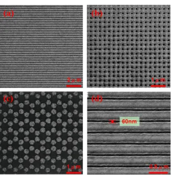
Figure 1. (a) SEM image of patterned lines, 250 nm wide, of spin-coatable LSMO resist. (b) SEM image of a large array of 125 nm lines. (c) SEM image of a periodic pattern with honeycomb style. The diameter of the light-coloured circle in the centre is 400 nm. (d) SEM image of a patterned line: the designed pattern is of straight lines with a width of 240 nm and an interval of 60 nm.
function spin-coatable resist lithography method. Figure1(a) shows an SEM image of patterned lines, 250 nm wide, of spin-coatable LSMO resist. Figure1(b) shows an SEM image of a large array of 125 nm lines. Figure1(c) shows an SEM image of a large area periodic pattern with honeycomb style. The diameter of the light-coloured circle in the centre is 400 nm. Figure1(d) shows an SEM image of a patterned film consisting of spin-coatable LSMO resist: the designed pattern is of straight lines with a width of 240 nm and a interval (distance between lines) of 60 nm. The line width roughness (σ) is about 3.7 nm: this was measured by atomic force microscopy (AFM, Digital Instruments, Dimension-3100 Multimode). Various patterns can be easily fabricated using spin-coatable LSMO resist by electron-beam lithography.
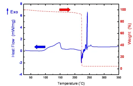
In order to understand the nature of the electron-beam thermal mechanism in the spin-coatable LSMO resist, we removed the water from the LSMO solution to form a gel first then subjected the gel to differential scanning calorimetry (DSC, Du Pont, TA 2910) and thermogravimetry (TGA, Du Pont, TA 2950) analyses. The results are shown in figure 2. The DSC plot shows exothermic peaks ranging from 100 and 150◦C that are due to the crosslinking of the PVA. The TGA curve illustrates a major decomposition at around 223◦C. That indicates the autoignition behaviour as shown by a sharp and nearly vertical step. The result is consistent with an intense exothermic peak at 221◦C in the DSC. This type of decomposition, with a very sharp and intense exothermic reaction, indicates a self-propagation combustion process which has been observed earlier in a few other systems [27, 30–32]. The autoignition of the gel occurs by a thermally induced oxidation–reduction reaction where PVA acts as a fuel and NO−3 as an oxidant.
Figure 2. TGA and DSC plot of a spin-coatable LSMO resist.
Figure 3. X-ray diffraction patterns of spin-coatable LSMO resists which were calcined at different temperatures.
The autoignition can be induced by mixing an appropriate ratio of the fuel and the oxidant, giving rise to a single-step decomposition associated with a particular reaction temperature and appreciable exothermic energy so as to facilitate the preparation of LSMO.
To further confirm the formation of LSMO crystalline structure from spin-coatable LSMO resist, we used the x-ray diffraction (XRD) pattern (using a Philips PW1830 diffractometer) of the spin-coatable LSMO resist calcined at high temperature (900◦C) as a control standard. Then we compared it with the XRD patterns obtained from the samples prepared at different temperatures and times. The results are shown in figure 3. The XRD patterns of the samples calcined at 150 and 200◦C, respectively, exhibit an amorphous structure because those temperature are lower than the autoignition temperature of the resist according to our TGA data, whereas the sample calcined at 250◦C shows the formation of the rhombohedral phase of La0.7Sr0.3MnO3 with traces of MnO2. The XRD pattern of the sample
Table 1. Energy dispersive x-ray analysis of elements C and N in the spin-coatable LSMO resist under different conditions.
Element analysis
Carbon element Nitrogen element La0.7Sr0.3MnO3 (wt%) (wt%) E-beam (60 mC cm−2) 0.9 0.1 300◦C, 1800 min 2.1 0.3 300◦C, 30 min 3.1 1.6 250◦C, 30 min 4.9 2.0 200◦C, 30 min 12.9 5.4 150◦C, 30 min 19.7 7.3
calcined at 300◦C clearly indicates the formation of the high-symmetry pseudocubic phase of La(Sr)MnO3containing trace MnO2 and La2O3 impurity phases. The sample calcined at 900◦C indicates the change from the rhombohedral structure to the pseudocubic form of the perovskite-like structure. The relatively low formation temperature of this phase is attributed to the high reactivity of the homogeneously dispersed ultrafine gel together with the sudden release of thermal energy during the combustion process. This formation temperature is much lower than what has been reported by other investigators employing other chemical methods [27,33].
An energy dispersive x-ray analysis (EDAX, Philips, XL-30) was used to monitor the amount of the elements C and N in the spin-coatable LSMO resist prepared either with different thermal treatment or with electron-beam lithography treatment. The results are shown in table 1. The elements C and N are from the PVA and metallic nitrates respectively, so they were the indication of the formation of the perovskite phase. The electron-beam treated samples have the least amount of both elements. This result also reveals that the energy from the electron-beam treatment is greater than that from thermal treatment above 300◦C. Therefore, we would obtain a perovskite structure of spin-coatable LSMO resist upon exposure to the electron beam.
The formation of the perovskite phase of the spin-coatable LSMO resist was further investigated by time-resolved Fourier transfer infrared spectra (FTIR, Thermo Nicolet, Nexus 470)
Figure 4. Transmission electron microscopy image of spin-coatable LSMO resist after electron beam exposure. The inset is the selected area diffraction pattern of the patterned LSMO magnetic resist.
acquired in reflectance mode. The absorption peak observed at about 3400 cm−1is attributed to the hydroxy group of metallic nitrates containing crystalline water. When the calcined temperature was increased, the peak associated with hydroxyl group was reduced, which indicated the formation of LSMO
0.01 0.1 1 10 100 1000 -0.6 -0.4 -0.2 0.0 0.2 0.4
i
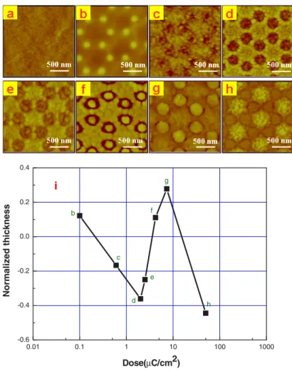
Nor m al iz ed thickness Dose C/cm2 b c d e f g hFigure 5. The surface morphology of spin-coatable LSMO resist with different electron dose times. (a) 0 mC cm−2, (b) 0.1 mC cm−2, (c) 0.6 mC cm−2, (d) 2.0 mC cm−2, (e) 2.5 mC cm−2, (f) 4.2 mC cm−2, (g) 7.3 mC cm−2, (h) 50.0 mC cm−2, (i) sensitivity curve of spin-coatable LSMO resist. The resist thickness is 180 nm.
negative resist with the increase of electron dose. Figure 5
illustrates the AFM images of LSMO patterns on Si substrate with different electron dose times. The AFM image of as-spin coated sample is illustrated in figure5(a). The film was very smooth with an RMS roughness of 0.37 nm. Figure5(b) shows the AFM image of a regular honeycomb array of 100 nm diameter and 500 nm lattice constant LSMO rods at an electron dose of 0.1 mC cm−2. This step indicates that the spin-coatable LSMO resist can be fabricated into negative patterns due to the crosslinking of the PVA. With
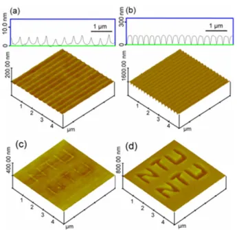
Figure 6. Topographic atomic force microscopy images of dual function spin-coatable LSMO resist. (a) Cross-sectional profiles and AFM images of negative LSMO resist with an electron dose of 0.1 mC cm−2. The height of the grating is 6 nm. (b) Cross-sectional profiles and AFM images of positive LSMO resist with an electron dose of 2 mC cm−2. The height of the grating is 115 nm. Both negative and positive resist can achieve about 60 nm line width resolution. (c) AFM images of negative LSMO resist with an electron dose of 0.1 mC cm−2. (d) AFM images of positive LSMO resist with an electron dose of 2 mC cm−2. Directly writing complex features using LSMO resist can be achieved.
the increase of electron dose, the thermal energy of electron beam will transfer to the neighbouring area and make all of the PVA crosslink. As illustrated in figure 5(c), the PVA starts to decompose at the direct beam location. Finally, the spin-coatable LSMO resist becomes a positive pattern with an electron dose of 2 mC cm−2(figure5(d)). The RMS roughness of the spin-coatable LSMO illustrated in figure5(d) is about 7.8 nm. Above this threshold electron-beam thermally energy, the increase of electron dose starts the autoignition process of LSMO. Figures 5(e), (f) and (g) show the AFM images of a regular honeycomb array with the electron dose of 2.5 4.2 and 7.3 mC cm−2, respectively. With an electron dose higher than 50 mC cm−2, the LSMO honeycomb patterns eventually collapsed, as illustrated in figure5(h). Figure5(i) illustrates the sensitivity curves of the spin-coatable LSMO resist after electron beam exposure and development.
Both the negative and positive properties of spin-coatable LSMO resist can achieve nanoscale resolution. The 3D AFM topographic images and cross-sectional profiles of a section of negative and positive spin-coatable LSMO resist with 60 nm line width corresponding to an electron dose of 0.1 mC cm−2 and 2 mC cm−2respectively are shown in figures6(a) and (b). The period of the fabricated grating was 300 nm. It is obvious from the photograph that the heights of gratings are uniform. This dual function spin-coatable LSMO resist is also capable of directly patterning large and complex features by controlling the dose time. Figure6(c) shows the AFM image of negative spin-coatable LSMO resist features that were written at an
Figure 7. The relationship of the negative magnetoresistance (MR) ratio and the temperature for the spin-coatable LSMO resist calcined at 900◦C under different external magnetic field strengths.
electron dose of 0.1 mC cm−2, and figure 6(d) shows the positive spin-coatable LSMO resist features that were written at an electron dose of 2 mC cm−2. The results illustrate that the capability of spin-coatable LSMO resist can be either positive or negative by varying the electron doses. The development of spin-coatable LSMO resist is an important research topic in the study of a new magnetic resist with both positive and negative resist properties, water-soluble solvent developable property, and the capability of preparing nanoscale patterns.
All the samples for the refractive index and film thickness measurements were deposited on a silicon wafer. The refractive index and film thickness were determined by spectral microreflectometry (Mission Peaks Optics, MP100-M), by measuring the interference between incident and reflected light with wavelengths ranging from UV to visible (250–1000 nm). From the phase shift, the film thickness and refractive index (n
andk) can be determined. The film thickness of spin-coatable LSMO resist approaches 180 nm, and the refractive index is about 2.38.
In order to study the magnetic properties of spin-coatable LSMO resist, the resist sample was calcined at 900◦C for 4 h first, then the magnetoresistance of the sample was evaluated by a physical properties measurement system (PPMS, PPMS-9, Quantum Design). The relationship between the temperature and the resistance of the samples under different external magnetic field strengths was obtained in order to understand the influence of the external magnetic field on the resistance. External magnetic field strengths of 10 000, 50 000, and 90 000 Oe were selected to observe the changes in the resistance under different external magnetic field strengths. The resistance of spin-coatable LSMO resist increases gradually as the external magnetic field strength increases, as shown in figure7. Therefore, the influences of the external magnetic field on the spin-coatable LSMO resist samples show negative and colossal magnetoresistance effects.
4. Summary
We have presented a novel positive and negative dual function water-based magnetic resist material. The
water-Financial support obtained from the National Science Council of the Republic of China (NSC-94-2120-M-002-010) is highly appreciated. The authors also thank C H Kuan, C W Chen, H L Chen, Mr M Y Tu, Mr Y Y Lin, Mr K T Huang and Mr W H Gan of National Taiwan University for helpful discussions. The electron-beam lithography was carried out using the Elinox facility located in the National Taiwan University Center for Information and Electronics Technologies.
References
[1] Saifullah M S M, Subramanian K R V, Kang D-J, Anderson D, Huck W T S, Jones G A C and Welland M E 2005 Adv.
Mater.17 1757
[2] Saifullah M S M, Subramanian K R V, Tapley E, Kang D-J, Welland M E and Butler M 2003 Nano Lett.3 1587
[3] Subramanian K R V, Saifullah M S M, Tapley E, Kang D-J, Welland M E and Butler M 2004 Nanotechnology15 158
[4] Alexe M, Harnagea C, Visinoiu A, Pignolet A, Hesse D and G ¨osele U 2001 Scr. Mater.14 1175
[5] Chen J K, Ko F H, Chen H L and Chang F C 2003 Japan. J.
Appl. Phys.42 3838
[6] Chen J K, Ko F H and Chang F C 2005 Adv. Funct. Mater.
15 1147
[7] Lin Q, Steinh¨ausler T, Simpson L, Wilder M, Medeiros D R, Willson C G, Havard J and Fr´echet J M J 1997 Chem. Mater.
9 1725
[17] Mao Y, Felix N M, Nguyen P T, Ober C K and Gleason K K 2004 J. Vac. Sci. Technol. B22 2473
[18] Zener C 1951 Phys. Rev.81 440
[19] Jin S, Tiefel T H, McCormack M, Fastnacht R A, Ramesh R and Chen L H 1994 Science 264 413 [20] Mahesh R, Mahendiran R, Raychaudhuri A K and
Rao C N R 1996 Appl. Phys. Lett.68 2291
[21] Wu Y, Suzuki Y, Rudiger U, Yu J, Kent A D, Nath T K and Eom C B 1999 Appl. Phys. Lett.75 2295
[22] Fontcuberta J, Bibes M, Martinez B, Trtik V, Ferrater C, Sanchez F and Varela M 1999 J. Appl. Phys.85 4800
[23] Yang S Y, Kuang W L, Ho C H, Tse W S, Lin M T, Lee S F, Liou Y and Yao Y D 2001 J. Magn. Magn. Mater.226 690
[24] Haghiri-Gosnet A M and Renard J P 2003 J. Phys. D: Appl.
Phys.36 R127
[25] Lu H B et al 2004 Appl. Phys. Lett.84 5007
[26] Geck J, Wochner P, Kiele S, Klingeler R, Reutler P, Revcolevschi A and Buchner B 2005 Phys. Rev. Lett.
95 236401
[27] Basu R N, Pratihar S K, Saha M and Maiti H S 1997 Mater.
Lett.32 217
[28] Huang K Q and Goodenough J B 2000 J. Alloys Compounds
303 454
[29] Lee H K 2002 Mater. Chem. Phys.77 639
[30] Chakraborty A, Devi P S, Roy S and Maiti H S 1994 J. Mater.
Res. 9 986
[31] Gaudon M, Laberty-Robert C, Ansart F, Stevens P and Rousset A 2002 Solid State Sci.4 125
[32] Antony S A, Nagaraja K S, Reddy G L N and Sreedharan O M 2001 Mater. Lett.51 414
[33] Majewski P, Epple L, Rozumek M, Schluckwerder H and Aldinger F 2000 J. Mater. Res. 15 1161