Dependable Wavelength Routing with Spare Rerouting
in All-Optical WDM Networks
Chuan-Ching Sue and Sy-Yen Kuo
Department of
Electrical Engineering
National Taiwan University
Taipei, Taiwan
Email: [email protected]. tw
Abstract
Path protection with shared spares is a general dependable wavelength routing (DWR) method to improve the blocking performance while minimizing the required spare resources. However, in a dynamic traffic environment, this may still lead to poor performance. This paper presents a dependable wavelength routing with spare rerouting mechanism (DWR-SR) to improve the blocking performance. Extensive simulation experiments were conducted to study the performance of the proposed DWR-SR method. The results show that DWR-SR can effectively alleviate the dynamic traffic constraint on the spare lightpaths and reduce the blocking probability.
1.
Introduction
All-optical networks employing wavelength division multiplexing (WDM) and wavelength routing have been a viable solution to emerging applications in future WANs [l, 51. Since the failure of a network component (e.g. a fiber link) can lead to the failure of all the lightpaths that traverse the failed component, it is beneficial to consider a dependable wavelength routing (DWR) mechanism to protect WDM all- optical networks from single-link failures [2,3,4,6,7].
There exist several approaches to ensuring network survivability [lo-141. The methods for recovering from failure are either protection-based or restoration- Acknowledgement: This research was supported by the National Science Council, Taiwan, R.O.C., under Grant NSC 89-2219-E- 002-029.
based. The restoration-based method is more efficient in resource utilization, but it does not guarantee successful recovery. To overcome the above problem, the protection-based method using the pre-configured spare route and wavelength can be employed. However, this method reserves excessive resources. Hence a spare sharing technique can be used to reduce the required spare resources. Besides, path protection is more efficient in utilizing spare resources than link protection. Thus, a
DWR
mechanism based on path protection with sharing is employed in this paper.Our work studied the DWR in a WDM network with dynamic traffic demand. In a dynamic traffic environment, a routing scheme that effectively uses spare sharing will tend to multiplex more and more spare lightpaths on a wavelength of a link. It is highly likely that a wavelength of a link is held by a spare lightpath for an extended period of time. Although this may benefit new connections when they can use this wavelength of a link for their spares, it would prevent new connections from using this wavelength as a working lightpath.
In this paper, a spare rerouting (SR) method is proposed to enhance the
DWR.
SR
is a viable and cost effective mechanism that can reduce the blocking probability, since wavelength converters are expensive [8, 91. The basic idea is to reassign several existing spare lightpaths on new wavelengths. This has big advantage compared with the conventional rerouting [8, 91, which is very expensive in terms of service disruption and control overhead because the working lightpaths must be interrupted and restarted. The simulation results show that DWR-SR can effectively alleviate the dynamic traffic constraint on the spare lightpaths by reducing the blocking probability between 17.5%-26.9%.The rest of this paper is organized as follows. Section 2 introduces the dependable wavelength routing mechanism. The spare rerouting scheme for dependable wavelength routing is proposed in Section 3. Section 4 describes the performance results. Section 5 concludes this paper.
2.
Dependable wavelength routing
2.1. System configurationAn optical network is modeled as a graph G(V, E ) where Vis the set of nodes and E the set of links. The bandwidth of each optical fiber link is wavelength- division multiplexed into a set of w wavelengths, A =
{A,,
A2, ..., A,,,]. Each node is assumed to have asufficiently large number of optical transceivers such that a new request will not be blocked due to a lack of optical transceivers. Each link is assumed to have two opposite directional fibers, and connections in the network are taken to be bi-directional for simplicity of presentation. Further, single link fault model is assumed.
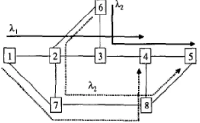
The architecture of a wavelength-routed optical network, shown in Fig. 1, consists of optical cross- connects (labeled 1 through 8) interconnected by fiber links. Each network link consists of a pair of unidirectional fiber links. Technological constraints dictate that the number of WDM channels that can be supported in a fiber be limited to W. The value of W is a few tens today, but it is expected to improve with time. An access station is connected to each optical cross-connect. For clarity of illustration, we will group the access station and the optical cross-connect together as an integrated unit and call it a network node.
..qy-T/
'... i ....' i..." ... " .... i" ... /".,
".
I i x / z I 1 b''\%..\I
;iz!A/
....
" ... " .... 1" ... /".
....
I XU ;U
'..
iFig. 1. A wavelength-routed all-optical network In this paper, we assume that there is no wavelength conversion in the network. In the absence of wavelength converters, a lightpath is established between two nodes by allocating the same wavelength throughout the route and uniquely identified by a
A3
wavelength and a physical path. Two lightpaths on a fiber link must be on different wavelengths to prevent the interference of optical signals. Fig. 1 shows the following wavelength-continuous lightpath pairs: (a) between Nodes 6 and 5 on working wavelength hZ and spare wavelength h2, and (b) between Nodes 1 and 4 on working wavelength hl and spare wavelength h3.
The bold lines are for the working lightpaths and the dashed line are for the spare lightpaths, respectively. 2.2.
Routing
Our scheme basically uses alternate routing method for connection requests. For every connection pair, a set of K candidate routes are pre-computed off- line. Let
H
be the hop length of the longest candidate route. The candidate routes of a connection pair are chosen to be edge-disjoint to incorporate fault tolerance. The routes for a connection pair are kept in increasing order of their hop lengths. A WDM network with N nodes and W wavelengths per fiber can be thought of as a network with W parallel layers each corresponding to a wavelength. In graphical representation, it is a graph with W sub-graphs each corresponding to a wavelength. In the following, we use the term 'link' to refer to a 'physical link' and 'w- link' to refer to a 'wavelength on a physical link', respectively. Therefore, one link is said to consist of W w-links. We use R, and R, to denote the candidate route as a working and spare route, respectively. Similarly, h, and k, denote the wavelength used by a working and spare lightpath, respectively. The pair <R,G denotes a working lightpathL,
and the pair&,,A,>
denotes a spare lightpath L,. A connectionrequest is realized by a working and spare lightpath pair CL,,, Ls>.
We use a cost function
C
,
andC,
to find the cost of a working and spare lightpath, respectively. Finally, the cost of a connection using the working-spare lightpath pair<L,+,
Ls> is given by C(L,+,Ls)=Cw(L,,,)+Cs(Ls,L,,,). Our objective is to find a
working-spare lightpath pair whose cost is the smallest.
The cost of a w-link on a working lightpath depends only on the current status of the w-link and requires constant time. However, the cost of a w-link on a spare lightpath depends not only on the status of the w-link but also on the working route of this connection and the working routes of all the
connections whose spare routes are multiplexed on this w-link.
2.2.1. WS-I method
The first method for assigning wavelengths without restrictions is called WS-I. We do not impose any restriction on the use of wavelength for the working and spare lightpaths and can choose the best possible <LS, L a pair to satisfy a connection request. This method has the advantage of better network performance in terms of the blocking probability, but it is more complex since additional data structures are required to maintain the information that would help to determine the cost of a w-link on a spare lightpath for a given working ligthpath. It uses a two dimensional array called TJw-link, link] for every pair of w-link and link. If
11
denotes a w-link on a wavelength h of a link 1 and m denotes another link, then T'[%, m] signifies that there exists a connection whose spare lightpath uses h~ and whose working lightpath is on link m. Whenever a connection is established, the information about the conflict between each of the w-links on its spare lightpath and each of the physical links on its working lightpath is recorded by updating entries i n the conflict table T,. When this connection terminates, the above information is deleted from Tc.Now consider a wavelength i. There are K possible working lightpaths. Process the working lightpaths one by one. Find a minimum cost spare lightpath on any wavelength for each of these working lightpaths. Consider a working lightpath L.,,, with some finite cost. There are K-1 possible spare routes each on one of the W possible wavelengths. Therefore, for this L, there are (K-l)W possible spare lightpaths. To compute C,y
of a spare lightpath L,, for the given working lightpath LV, we need to find the cost of each of the w-links on the spare lightpath L,. If the w-link is free, its cost is 1. Otherwise, its cost depends on the conflict table T,.
If the w-link is in conflict with a working lightpath, its cost is infinity. Otherwise it is 0. A w-link is said to be in conflict with a working lightpath, if at least one related entry has been registered in the conflict table T,. The related entry T,[A,, m] is that m is on the given working lightpath
L,,,
and A, is the related w- link. To decide if a w-link is in conflict with a working lightpath, it requires O(H) time units. Therefore, for a given working lightpath on a givenwavelength, choosing the best spare lightpath on any wavelength will require O(KH2W) time units. We need to process every working lightpath on every wavelength to determine the minimal cost working- spare lightpath pair to satisfy the connection request. The overall time complexity of this method thus becomes O(K2H2W2). In practice, K and H are small and thus the actual running time is acceptable. 2.2.2. WS-Di method
Here, the conflict table is not used at all. Thus, a restriction on choosing the wavelength on the working-spare lightpath pair needs to be imposed. The restriction is the fixed relationship between the wavelengths on the working and spare lightpaths. The selection of wavelengths between the spare and working lightpaths can be done by one of the methods WS-Di where i = 0, 1, 2, .. ., W-1.
For the WS-Do method, a working-spare lightpath pair on the same wavelength is chosen. It may not yield the best performance due to the restriction on choosing the wavelength. For example, the request will be rejected even there exist wavelength- continuous routes for the working lightpath on one wavelength and for the spare one on another wavelength. However, it is simpler and does not require the conflict table T, to decide if two spare routes could be multiplexed on a w-link or not. From the bi-directional assumption, it is clear that two working routes on the same wavelength must be link- disjoint. Therefore, if several spare routes are multiplexed on a w-link, a new spare route can still be multiplexed on it without requiring any procedure to check if its working route is link disjoint with the working routes of the already multiplexed spare routes. Now we describe the procedure to choose the least cost pair of lightpaths for establishing a connection between the pair a, d>. Consider a wavelength i. There are K candidate routes for <s, d> and hence K
possible lightpaths. For every lightpath, compute C,,, and C,. This can be done in O(KH) time units. Choose a lightpath L,,, whose C, is minimum. Then among the lightpaths other than L,, choose a lightpath L,T whose C,T is minimum. It is easy to verify that the pair <& LS> has the minimum C value. This procedure is repeated for each of the W wavelengths to choose the minimum cost lightpath pair. The complexity of the WS-Do method is thus O(KHW).
For WS-Di (i#O) method, for any working lightpath on wavelength j , the spare ligthpath must be on wavelength k (k#j). That is, for any working lightpath on wavelength j , the spare lightpath must be on wavelength G+i) mod W if WS-Di is executed. In this case, two spare lightpaths can always be multiplexed on a w-link because their working lightpaths are automatically link disjoint. Similar procedure as that of WS-Do can be adopted. However, we need to choose the best spare lightpath for each of the working lightpaths separately. Thus the complexity of the WS-Di (i#O) becomes O(K2HW). 2.2.3. Pseudo code
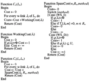
We give below the pseudo code for the working and spare cost functions, C, and C,, respectively. Function C,,(L,) Function SpareCost(w,,R,,,nierhod)
Be in
Begin Eost, 0
cost t 0 Switch (methud)
For every w-link 1, of L, do
CosttCost +WorkingCost(/z/) Costt 1
Return (Cost) Else if TL[/z,.m] =0, n1 E R,,
C o s t t 0 Else (Case (ws-l): If q(/z/)=@ End Function WorkingCost(/z/) Be13:st t 0 If q(A,)=@ cost t 1 Else Cost t
-
Return (Cost) . , End Function C,(L,,L,) Begin C o s t t-
C o s t t 1 Else if q(1,) E U, cost f- 0 Else cost t - 1 Return (Cost) Case (WS-Di): If y(/z,)=Q End Cost t 0For every w-link 1, of 15, do cost t cost +
SpareCost(1,. R,,, nierhod)
Return (Cost) End
A few notations are defined first. U = {U,,, U s } is the set of existing lightpaths in the network at the time of interest. U , and U, are for the working and spare lightpaths, respectively. u 0 = {U:, U: } is the new connection request. The network occupancy function q(&)=(u I h, is on the U E U ) is used to
record the status of the w-link. During the Connect and Disconnect operation, q(4) needs to be updated.
Initially q(&) =
a.
When u 0 ={ u , W , U ~ }
is determined in the connection, q(/2r)={ U: } if connection U," uses4,
q(&={ U: )U q(4) if connection U: uses4,
or q(&) remains unchanged ifA/
is not used at all. When a connectionU , = {U: , u s } is disconnected, q(/2)= for each
/2
on the connection u,y and q(&)=q(A/)-{ U,' } for eachA/
on the connection3.
DWR with
spare
rerouting
The disruption time of the traditional rerouting algorithm can be serious for high-speed transmission since some working lightpaths need to be moved to new wavelengths to avoid blocking. Thus, the proposed method is performed only on the spare lightpaths. The difference between the working rerouting and spare rerouting is that (a) the working lightpaths are always disjoint and the spare ones can be shared. (b),the tunable working lightpaths can only move to free w-links but the tunable spare lightpaths can move to either free or shareable w-links. (c) The spare rerouting does not require the high time complexity operations on tuning the working lightpaths.
For illustration, consider the same network graphic representation as Fig. 1 but with an additional lightpath between Node 3 and 8 in Fig. 2.
Assume there are only three wavelengths in each bi-directional links. Thus, only free wavelength
h3
is available for the working lightpath 3-4-8 since h, and h2 on link 3-4 is used by the working lightpaths 1-2-3- 4 and 6-3-4-5. Without spare rerouting, the additional request for lightpath 3-8 is blocked. A possible spare rerouting is by tuning the wavelength h3 to hl in the spare lightpath 1-7-8-4. The workinglightpath 3-4-8 with h3 and the spare lightpath 3-2-7-
8 with h3 can thus realize the additional request for connection 3-8.
. "
A,+ h,
Fig. 2. Example spare rerouting A spare rerouting (SR) does not make the spare resources fixed and can change the wavelength or the route of the existing spare lightpaths to satisfy a new connection request. Simultaneously changing the
wavelength and the route is difficult as shown in [8]. ?Even changing the wavelength only is also NP-hard ;[8]. And changing the path needs more additional information than the conflict table T,. Thus we employ the same idea as in [8] that spare rerouting is based on the wavelength tuning, that is, it tunes the wavelength of a lightpath but maintains its path. It has certain advantages. First, it facilitates control because the old and the new routes share the same switching nodes. Second, it reduces the calculation of optimal rerouting path because only changing the wavelength of an existing spare lightpath needs to be considered. Third, it significantly reduces the disruption period in the connection setup when it is combined with move-to-free strategy in a wide-area network because move-to-free method reroutes a lightpath to a free route with no other lightpaths and thus does not interrupt other lightpaths. Move-to-free is a polynomial-time heuristic to simplify the wavelength tuning [8]. The network controller sends control messages to the intermediate nodes on the path of the rerouted lightpath to setup a new spare route on a free wavelength. In the following subsections we will first introduce how to maintain the tunability status. Then we describe our algorithm in detail and explain how to define cost to make the number of tuned spare lightpaths smaller. Here the concept of crossover edge is introduced and we derive the linear and equalized cost for C,. Finally, we also discuss the complexity of our algorithm.
3.1. Maintenance of tunability status
The tuning function is ‘defined for each spare lightpath according to the wavelength on the new route of the rerouted lightpath. If the new w-link is free, it is the basic move-to-free method. If the new w-link is shared, it needs the conflict table T, to check the tunability and is called the move-to-available method.
Define
g,(u“) and g,(u”)
,
U E U , as the tuning functions for the move-to-free and the move-to-available methods, respectively. Assume that an existing spare lightpathus E U passes through the sequence of links
Zj,
j=1,. . .
,h(us)), on the wavelength h, where h(us) is the hop count of us. First gkus) is defined. gkus)=h, if us can be tuned to the free wavelength on the same path with the smallest index h, i.e., h=min{A’EA: q(A’,) = O,j
A few notations are defined as follows.
=1, ..., h ( u s ) ) , and g,(us)= 0, otherwise. A tunable lightpath us is gkus)# 0. Next we define ga(us). The move-to-available method finds the shared w-links as well as the free w-links on the new route. Thus, g,(u’)=h, if ur can be tuned to free or shared wavelength on the same path with the smallest index
h, i.e., h=min{A’EA: T,[A’,, Lk] = 0, j =1, ..., N u s )
and k = l , ..., h(uw)}, and g,(u‘)= 0, otherwise. Our
g,(us) function directly uses T, to find the free and shared w-links instead of separately using q to find free w-links and using T, to find shared ones.
When a w-link is to be rerouted, all shared spare lightpaths associated with this w-link should be tuned immediately. Although the information provided by the tuning function is only for a single spare lightpath, the algorithm can use the information for all shared lightpaths to obtain the consistent state. There will be no confusion that one is to be tuned while the other is not to be tuned on the same w-link. In addition, the lightpaths that are determined to be tuned will not conflict with each other, although we allow parallel rerouting. This is because only wavelength tuning is allowed in our method such that disjoint lighpaths will remain disjoint and the shared lighpaths will remain shared or become unshared. On the other hand, if path rerouting is allowed, additional information other than T, is required since the latter decision affects the former decision.
3.2. Description of the algorithm
As the controller receives a new request, Phase I will try to find a lighpath pair, consisting of a sequence of links and a proper wavelength for working and spare lightpaths without rerouting. If the initial attempt fails, the controller will execute Phase 11. It will determine which existing spare lightpaths should be rerouted and how they should be rerouted if rerouting is feasible. Then the controller will send control information to certain nodes for setting up a new connection and rerouting the existing spare lightpaths used by the active connection. If the rerouting is infeasible, the new connection request is rejected. Phase I1 proceeds in three stages. In Stage 1, it identifies all the tunable spare lightpaths using q
and g functions. To determine whether a spare lightpath on some wavelengths with ne edges is tunable, O(n,W) time units are required in the worst case. Considering all the spare lightpaths on all the
wavelengths, it can be seen that the worst case time complexity of Stage 1 is O(N2Wz). In fact, the tuning function g depends on move-to-free and move-to- available. In Stage 2 , it calculates the cost according to q and g functions. And the working and spare lightpaths are found from the cost functions and the pair with minimum weighted number of rerouted lightpaths is chosen. If no pair with a finite cost can be found, the connection request is rejected. The complexity of this stage is the same as Phase I. Finally, in Stage 3, update q according to the selected L, and L,?. Therefore, the worst case complexity of this algorithm is O(KzH2Wz+NzW2).
Since Stage 1 of Phase I1 has been introduced in the previous subsection, in the following we will describe the new cost function for finding the minimal weighted number of rerouted spare lightpaths in detail.
Two kinds of rerouting cost are assumed: equalized weight, i.e., c, = c, U E U , and linear weight which is proportional to the number of hops in the rerouted lightpaths, i.e., c, = h(u), U E U . To correctly determine the weighted number of rerouted lightpaths, we can virtually add some crossover edges along the route of a tunable lightpath. Crossover edges are defined as h/(u), where 1 E U and g(u)
f a .
Thesecrossover edges can avoid repeatedly counting the weighted number of rerouted lightpaths for the same new connection request. In our method, we use
Cross(u) to keep the information of crossover edges.
Cross(u) is assumed to be initialized to 0.
Therefore, a tunable edge is either a crossover edge or an edge associated with a spare channel used by a tunable lightpath, i.e., in the set of
(4:
1 E E , q(A,)#@, g[Vq(4)] #@}. Idle edges are in the set of (A/:
1 E E ,q(A/)=@}. The non-tunable edges are those in the set of {
A:
1 E E , q(A/)#@, g[Vq(A)]#a)}.
The cost function of each edge in the graph is determined by whether an edge is idle, tunable,or
non-tunable. Cost for an idle edge is a small positive constant E while cost for a non-tunable edge is infinite. Cost for a tunable edge associated with a tunable lightpath U isc, which is a positive weighting factor indicating the penalty of rerouting an existing lightpath U to
accommodate the new connection. c, > lEle is assumed to prevent our objective of minimization of the weighted number of rerouted lightpaths from being changed by large values of E. Actually, E thus chosen will force the given optimization to minimize the weighted number of rerouted lightpaths and then
minimize the number of idle channels to place the new connection request for the same minimal weighted number of rerouted lightpaths.
Since the functions g and Cross are initialized whenever they are needed, Stage 3 only update the q
function. On the other hand, when some connection is disconnected, the occupancy function q and the conflict table T, need to be updated to reflect the released lightpath pair.
In the following we give the pseudo code to determine the new cost function for the working lightpath of a new connection request.
Function C , ( L , )
Begin
cost t 0
For every w-link
A,
of L, doCost t Cost
+
WorkingCost(A1, c-mode) Return (Cost)End
Function WorkingCost(A,, c-mode) Begin
If q(A/)=@ do cost t E
Else if q(A/) E U" Cost t
Else for each spare lightpath U,' in
A/
do If c-mode = equalizedc,= c
Else c,=h(u)
cost t 0
If g(u") = h and Cross(us) = 0
Else if g(u')=@ cost t cost t cu Cross(u") = 1 Return (Cost) End
As for the cost function for the spare lightpath, it is the same as the DWR except that when computing C,
it needs to temporarily update the occupancy function q first according to the working lightpath with some finite cost. Therefore, finding an optimal solution with the DWR-SR scheme can be achieved in polynomial time as opposed to that of a general rerouting problem which is NP-hard.
4.
Performance study
We evaluate the effectiveness of the proposed DWR-SR method through extensive simulations. We use ARPA2 network with 21 nodes and 26 bi- directional links to generate numerical results. The connection requests of each node will arrive as a
Poisson process and will hold for exponentially distributed periods of time with unit mean. Every node is equally likely to be the destination node. A blocked connection request is cleared and will not be retried.
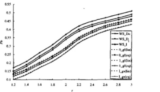
Fig. 3 plots blocking probability versus arrival rate per node for various schemes. The various schemes include the general DWR schemes, W S D o , WS-DI and WS-I, and the general schemes combined with our proposed SR-A (move-to-available) and SR-V
(move-to-free) under the two different cost models, linear and equalized. In order to clearly read the figures, we define the corresponding symbols for various DWR-SR schemes. We use X-gY(Z) to denote the scheme which uses the WS-Dx for X=O,l or WS-X for X=I as the general DWR and applies the proposed SR-A for Y=a or SR-V for Y=f under the linear cost model for Z=lin or the equalized cost model for Z=eq. The uppermost three curves are for the networks that perform the general DWR. The lowest curves are for the networks that perform our proposed DWR-SR with the help of T, and the tuning function g, for the linear and equalized cost schemes, respectively. The middle four curves are for the networks that perform DWR-SR without the help of T, and thus use the tuning function gt for the linear and equalized cost schemes, respectively. The trend of curves shows that the equalized cost scheme has almost the same blocking probability as the linear cost scheme. Taking the blocking performance of WS-Do as the baseline, the curves i n DWR show that WS-D, can improve the performance by 6.2%, WS-I can further improve the performance by 3.1%, i.e. 9.3% i n the improvement with the help of T,. While the WS-Do uses the spare rerouting with the tuning function g, in the equalized cost scheme, it can improve the performance by 17.5% more than the gain by only using T, in DWR as WS-I. This shows that DWR-SR really enhances the performance of DWR. To the extreme, the DWR-SR by WS-I+SR with g , can improve the performance by 26.9% using the equalized cost scheme. Overall, the results of the blocking performance show that DWR_SR with the help of both T, and g, (which is related to T,) is better choice than DWR-SR with only g, (which is not related to T , ) or DWR without SR.
The trend of the curves also shows that when the traffic load increases, the improvement of spare rerouting in the blocking performance decreases and
saturates. This is because our DWI-SR does not guarantee that the rerouted spare lightpaths remain shared if they are shared before rerouting. When the traffic load is increased to threshold, the available resources used by the rerouted spare lightpaths can affect future new connections.
0 5 015 0.4 0 .3' 0 3 0 2s 0 2 0 1 ' " I 1 2 I 4 16 l l 2 2 2 2 4 2 6 2 8 1
Fig. 3. Blocking probabilities of a network versus traffic loading per node
Fig. 4 plots the average number of rerouting spare lightpaths each time the DWR-SR rerouting is executed. The curves show that the average number of rerouted lightpaths increases as the load increases. The equalized cost scheme reroutes fewer lightpaths than the linear cost scheme because the equalized cost scheme concerns more with the number of lightpaths to be rerouted than the hops involved in rerouting. And the scheme using g, reroutes more lightpaths than the scheme using gf because the tuning function
g, can find the possible shared w-link in the new route of the rerouted spare lightpath. The average number of lightpaths rerouted is between 2-4, which is more than 1-2 i n [8,9] because the rerouted lightpaths contain some shared lightpaths in our method, but consists of only disjoint lightpaths in [8,9].
.
1 4 2 1
2 1 ' ' , ' ' I ' ' 1
I 2 I 4 1 6 1.8 2 2 2 2 4 2 6 2 8 1
Fig. 4. Average number of rerouted spare lightpaths versus traffic load per node Fig. 5 plots the average number of hops of rerouted spare lightpaths versus the arrival rate per node. The curves show that the linear cost scheme will tend to reroute shorter-hop lightpaths than the equalized cost one. This is because the linear cost scheme concerns
? 4
2 2
Fig. 5. Average number of hops of the rerouted spare lightpaths versus traffic load per node
F r o m Figs. 3-5, w e c a n conclude that although equalized or linear cost schemes i n t h e DWR-SR affect the number a n d t h e h o p count of t h e rerouted lightpaths, the major concern in t h e blocking performance i s t h e wavelength assignment method a n d auxiliary data structures.
-
l . m ” l .-. I L l l I r q l-
CldOW ‘....’.. .-.._-... U,\ * . :: ..,, -5.
Conclusions
In this paper, we employ spare rerouting (SR) to
improve t h e blocking probability of t h e dependable wavelength routing (DWR) mechanism i n all-optical WDM networks. DWR c a n be classified as WS-I or
WS-Di (i=I,
...,
W-1) depending o n whether t h e conflict table T, i s used or not. WS-I uses T, in t h e wavelength assignment on working and spare lightpaths, while WS-Di avoids using T, a n d is based o n t h e relationship between t h e working a n d spare lightpaths. T h e cost function uses t h e occupancy function q t o select t h e least cost lightpath pair. The proposed DWR-SR h a s two phases, with three stages i n t h e second phase. Performance results s h o w that t h e blocking probability i s reduced by an average of 26.9% when T, i s used a n d 17.5% when T, i s not used based o n t h e equalized cost scheme. In addition, each rerouting reroutes an average of 2-4 spare lightpaths i n a 21-node network.References
[ 11 B. Mukherjee, Optical Communication Networks, New York: McGraw-Hill, July 1997.
[2] P. Bonenfant, “Optical layer survivability: a comprehensive approach,” In OFC ’98, pp. 270-271,
Feb. 1998.
[3] 0. Gerstel, “Opportunities for optical protection and restoration,” in OFC ’98, pp. 269-270, 1998.
[4] T. Wu, Fiber Network Service Survivability, Norwood, MA: Artech House, 1992.
[5] R. Ramaswai and K. N. Sivarjan, “Routing and wavelength assignment in all-optical networks,”
IEEE/ACM Trans. on Networking, vol. 3, no. 5, pp. [6] C. S . Li and R. Ramaswaim, “Automatic fault detection, isolation, and recovery in transparent all- optical networks,” IEEE J. Lightwave technol., vol. 15,
no. 10, pp. 1784-1793, Oct. 1997.
N. Nagatsu, S . Okamoto, and K. Sato, “Optical path cross-connect system scale evaluation using path accommodation design for restricted wavelength multiplexing”, IEEE J. select. areas in commun., vol.
14, no. 5, pp. 893-902, June 1996.
K. C. Lee and V. 0. K. Li, “A wavelength rerouting algorithm in wide-area all-optical networks,” IEEE .I.
Lightwave Technol., vol. 14, no. 6, pp. 1218-1229, June
1996.
G Mohan and C. S. R. Murthy, “A time optimal wavelength rerouting algorithm for dynamic traffic in WDM networks,” IEEE J. Lightwave Technol., vol. 17,
no. 3, pp. 406-417, March 1999.
[lo] S . Ramamurthy and B. Mukherjee, “Survivalbe WDM Mesh Networks, Part I - Protection,” in ICC ’99,
[ l l ] J . Armitage, 0. Crochat, and J. -Y. L e Boudec, “Design of a survivable WDM photonic network,” in
0. Gerstel, R. Ramaswami, and G Sasaki, “Fault tolerant multiwavelength optical rings with limited wavelength conversion,” in INFOCOM ’97, pp. 508-
516, 1997.
S. G. Finn, M. Medard, and R. A. Barry, “A new algorithm for bi-directional link self-healing for arbitrary redundant networks,” in OFC ’98, pp. 298-
299, 1998.
[14] E. Limal, S . L. Danielsen, and K. E. Stubkjaer, “Capacity utilization in resilient wavelength-routed optical networks using link restoration,” in OFC ‘98, 489-500, Oct. 1995. [7] [8] [9] pp. 744-750, 1999. INFOCOM ’97, pp. 244-252, 1997. [I21 [13] pp. 297-298, 1998.