Abstract - The modeling and simulation methods for the manufacturing systems of conical milk cans are proposed. The processes adopted in this manufacturing system are divided into three stages: backward cup extrusion, ironing of the can body, and neck nosing of the can. The most crucial stage of this manufacturing system is the nosing process which usually takes many steps, vary from three to ten, to form the final shape and dimension precisely. The modeling of the maximum nosing rate is proposed to determine the steps required to make the can in the nosing stage. The conic curve model is proposed to design the nosing dies to minimize the nosing steps and obtain smoother material flow of forming process. Three-dimensional FEM simulations were carried out to evaluate the proposed die profile designs and validate the manufacturing system. The geometrical parameters of the proposed conic curves of die profile are optimized via the DOE method. The FEM simulation results show that the proposed die profile design method is capable of preventing the buckling defects and reducing the steps of nosing to three.
Keywords – Modeling and Simulation of nosing process, Conic curve nosing die, nosing rate limit, Slab method
I. INTRODUCTION
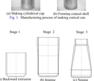
There are a lot of materials such as plastic, glass, and aluminium alloy, available for making milk cans with different manufacturing processes. In the view point of endurable reuse and recycling, the Aluminium alloy is a better choice than the other materials. The manufacturing system of making a conical milk can of aluminium alloy is usually divided into the preparation of cylindrical cup and the shaping of the can as shown in Fig. 1. A round aluminum billet is cut and extruded backwardly to make a cup with uniform thick wall. An ironing process is followed to elongate the cup height and redistribute the wall thickness according the product specification. Finally, a nosing operation is performed to shape the billet into a conical can with proper bottle neck thickness for threading. The process of the can making is schematically shown in Fig. 2 to demonstrate the main stages of the manufacturing system. The die designs of the first two stages are relatively easier than the last nosing stage because only one step is required in each of the backward extrusion and ironing stages. Many steps are required in the stage of nosing in order to form the conical can uniformly without defects of buckling in the longitudinal direction and wrinkling in the circumferential direction.
The nosing operation is very sensitive to the material flow which is controlled by the die profile design.
Fig. 1. Manufacturing process of making conical can.
Fig. 2. Schematic diagram of the conical shell manufacturing process.
An approximation model of the thickness variation for nosing process is proposed [1] to predict material flow of different die designs. Numerical solutions based on the finite element method [2] are proposed to evaluate the shell nosing process. Different preform designs are proposed to minimize the wall thickness variation of the nosed shell. Analytical model of shell nosing process simulation [3] is proposed considering the volume constancy and the Levy-Mises flow rule. The predicted loads and strain rate are in good agreement with the FEM simulations. DEFORM-3D software has been applied to simulate the process of cold eccentric shell nosing [4] and study the nosing ratio limit with respect to tube thickness, die fillet radius, die angle, friction factor, and flow stress of billet material. The inertial effects strongly influence the magnitude of the dynamic loads [5] so that the peak impact loads can only be assessed through a full dynamic analysis. Reference [6] uses the Prandtl-Reuss flow rule and the von Mises yield criterion to establish the finite-element model, simulation results indicate the forming load is changed slightly for different tube thicknesses while in good friction. A tool design method using two sharp-edge dies and a floating ring is proposed to enhance
(a) Backward extrusion (b) Ironing (c) Nosing
Stage 1 Stage 2 Stage 3
(b) Forming conical shell (a) Making cylindrical cup
Conical nosing
Cold Nosing Process Modeling and Simulation for Manufacturing of
Aluminium Conical Milk Can
Jinn-Jong Sheu
1, Hsien-Hsiu Su
2Department of Mold and Die Engineering, National Kaohsiung University of Applied Sciences, Kaohsiung 807, Taiwan
,
R.O.C.1[email protected] (professor), 2[email protected] (graduate student)
rate. This is the reason why the nosing steps of the new proposed design can be reduced.
Fig. 6. Deformation characteristics of nosing process.
C. Manufacturing simulation
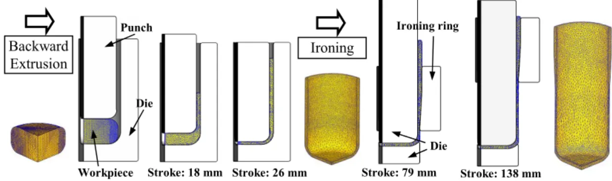
The manufacturing system of the milk can is modeled and simulated virtually using the FEM program. The cup extrusion and ironing process are shown in Fig. 9 which the workpiece is modeled with FEM mesh and the tools are modeled using STL solid of CAD. The deformed meshes of the backward extrusion and the ironing operations at the half and the final strokes are displayed to show the material flows. Uniform mesh means smooth material flows have been achieved. Fig. 10 shows the manufacturing simulation of nosing steps in three stages.
The strokes 125 mm, 96 mm, and 64 mm for three nosing steps are simulated successfully. The simulation of the manufacturing process shows the milk can has been produced without buckling and wrinkling defects.
V. CONCLUSIONS
A new design method of nosing die profile has been proposed and applied to the milk can manufacturing. The design parameters are optimized via the DOE design method. The manufacturing simulation shows the product is made free of buckling and wrinkling defects. The proposed die design method is capable of controlling the upward and inward material flows successfully. The required numbers of nosing steps of the new die design method are reduced to three without any defects.
Fig. 7. Development of nosing rate of the shell end of the three-stage nosing processes.
Fig. 8. Material flow characteristics of the conventional and the new die design profiles.
REFERENCES
[1] S. Kobayashi, “Approximate solutions for preform design in shell nosing,” Int. J. Mach. Tool Des., vol. 23, no. 2 3, pp. 111–122, 1983.
[2] J. Zhu, “A new approach to preform design in shell nosing,” J. Mater. Process. Technol., vol. 23, no. 63, pp. 640–644, 1997.
Conventional conical die profile
Die Shell open end
Proposed new conic-curve profile
Die Shell open end Neck nosing Body nosing
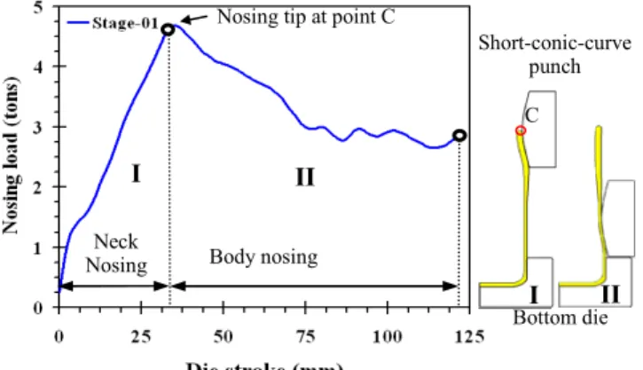
Nosing tip at point C
I II II Bottom die Long-conic-curve punch Neck
Nosing Body nosing Nosing tip at point C
I II II Bottom die Short-conic-curve punch Conical punch (conventional nosing die) Bottom die 8˚ 8˚ 93 mm 28 mm 50 mm Step 3
(a) Step 1: Short-conic-curve nosing
(b) Step 2: Long-conic-curve nosing
(c) Step 3: Finish sizing
C I C I 80 m m Conventional New design Nr=0.858
Proceedings of the 2009 IEEE IEEM
[3] Y. H. Lu, “Study of preform and loading rate in the tube nosing process by spherical die,” Comput. Methods Appl. Mech. Engrg., vol. 194, pp. 2839–2858, 2005.
[4] C. T. Kwan, “An analysis of the eccentric nosing process of metal tubes,” J. Mater. Process. Technol., vol. 140, no. 63, pp. 530–534, 2003.
[5] S. R. Rfid, and J. J. Harrigan, “Transient effects in the quasi-static and dynamic internal inversion and nosing of metal tubes,” Int. J. Mech. Sci., vol. 40, pp. 263–280, 1998. [6] Y. M. Huang, and Y. W. Taso, “Study of flaring and nosing process for clad tube in conic tool,” presented at the 6th
conference on Precision Machinery and Manufacturing Technology, pp. C45, 2008.
[7] L. M. Alves, and P. A. F. Martins, “Single-stage nosing of thin-walled tubes into hollow spheres using a die,” J. Strain Analysis, vol. 43, pp. 205–216, 2008.
[8] M. L. Alves, B. P. P. Almeida, P. A. R. Rosa, and P. A. F. Martins, “End forming of thin-walled tubes,” J. Mater. Process. Technol., vol. 177, pp. 183–187, 2006.
[9] M. Grzywiński, and A. Służalec, “Stochastic Equations of Rigid-thermo-viscoplasticity in Metal process,” Int. J. Eng. Sci., vol. 40, pp. 367–383, 2002.
Fig. 9. Manufacturing simulation of the backward cup extrusion and the can ironing processes.
Fig. 10. Manufacturing simulation of the nosing passes.
Pass 1 Pass 2 Pass 3
Stroke: 25 mm Stroke: 50 mm Stroke:75 mm Stroke: 100 mm Stroke: 125 mm Stroke: 32 mm Stroke: 64 mm Stroke: 96 mm Stroke: 64 mm Stroke: 18 mm Stroke: 26 mm Punch Die Workpiece Backward Extrusion Ironing Stroke: 79 mm Stroke: 138 mm Ironing ring Die Proceedings of the 2009 IEEE IEEM