國 立 交 通 大 學
資訊科學與工程研究所
博
博
博
博
士
士
士
士
論
論
論
論
文
文
文
文
適用於都會區車載網路的
動態覆蓋式群播機制
與基於道路之預測式多路徑繞徑協定
Dynamic Overlay Multicast and
Road-based Predictive Multipath Routing
in Urban VANETs
研 究 生:謝宜玲
指導教授:王國禎 博士
適用於都會區車載網路的
動態覆蓋式群播機制
與基於道路之預測式多路徑繞徑協定
Dynamic Overlay Multicast and
Road-based Predictive Multipath Routing
in Urban VANETs
研 究 生:謝宜玲 Student: Yi-Ling Hsieh
指導教授:王國禎 Advisor: Kuochen Wang
國 立 交 通 大 學
資 訊 科 學 與 工 程 研 究 所
博 士 論 文
A Dissertation
Submitted to Institutes of Computer Science and Engineering Department of Computer Science
National Chiao Tung University in Partial Fulfillment of the Requirements
for the Degree of Doctor of Philosophy
in
Computer Science and Engineering January 2013
Hsinchu, Taiwan, Republic of China
適用於都會區車載網路的
動態覆蓋式群播機制
與基於道路之預測式多路徑繞徑協定
學生:謝宜玲 指導教授:王國禎 博士
國立交通大學資訊科學與工程研究所
摘 要
在車載網路中,多媒體串流及群組通訊為兩種重要且有潛力的服務,而
一個高效能的繞徑協定將能顯著地提升來源端至接收端的多媒體串流效
能。因此,在本論文中,在應用層我們提出一個動態覆蓋式群播機制來提
供實況多媒體串流給群組節點;而在網路層我們提出一個新穎的服務品質
感知之基於道路多路徑繞徑協定。我們所提出的這兩個方法都旨在都會區
車載網路中提供流暢的多媒體串流服務。
在都會區車載網路的各種應用服務中,提供資訊娛樂服務(infotainment
service)已經是可預見的趨勢,而多媒體串流是潛力極高的資訊娛樂服務。
我們考慮的情境是在群組車輛間進行實況多媒體串流群播服務,為此我們
使用動態應用層覆蓋(dynamic application-layer overlay)方式來達成。由於非
群組中的車輛不一定願意合作來協助群播,因此以應用層覆蓋式群播的方
式會比其他種類的群播方式,如基於網路編碼之群播以及網路層群播,更
具彈性。因此,為了適應都會區車載網路高移動性及障礙物密集的特性,
我們提出了一個稱作 OMV (Overlay Multicast in VANETs)的高效能動態覆
蓋式群播機制來提供多媒體串流。在這個 OMV 方法中,我們提出兩項策略
來增強覆蓋(overlay)的穩定性:(1)滿足服務品質之動態覆蓋及(2)網狀結構
之覆蓋。滿足服務品質之動態覆蓋的策略是按照封包遺失率及端到端延遲
時間來挑選潛在的新父節點,以優化此覆蓋架構。而網狀結構之覆蓋的策
略是允許子節點可擁有多個父節點。我們採用了兩個真實的影音短片來評
估及驗證 OMV 在多障礙物的都會區車載網路中傳送影音的可行性。評估結
果顯示,相較於目前在車載網路上最佳的方法—Qadri 等人使用靜態網狀覆
蓋的研究,平均來說 OMV 降低了 27.1%的封包遺失率、11.7%的端到端延
遲時間,但只增加 2.1%的額外控制負荷。我們並將樹狀 OMV 與 ALMA 作
比較,其中 ALMA 為另一個樹狀覆蓋式群播且是行動隨意網路(MANETs)
中的最佳方法,OMV 降低了 7.1%的封包遺失率及 13.1%的端到端延遲時
間。此外,針對都會區車載網路中障礙物密集的問題,我們歸納出在不同
的道路疏密度下可行之串流速度與群組大小。據我們所知,現有的車載網
路文獻中尚未有如何動態地調整應用層群播覆蓋架構,以有效傳送多媒體
串流的研究。總結來說,為處理都會區車載網路中高變動的拓樸,我們提
出一個能滿足服務品質的策略,使群組節點可切換至能提供較佳服務品質
的新父節點。我們所提出的 OMV 適用於實況多媒體串流,例如緊急實況影
音傳輸及同一群組車輛的遊客們實況影音導遊。
至於在網路層中,穩定且效能高的繞徑是車載網路成功的關鍵。現有文
獻已經證明基於道路的繞徑方式是非常適用於車載網路。此外,一旦使用
中的路徑失敗時,多路徑繞徑方式可提供額外的路徑供切換。然而,現有
的多路徑繞徑協定皆為基於節點的繞徑方法,因此並不適用於都會區之車
載網路。在本論文中,我們也提出了一個適用於都會區車載網路之新穎的
服務品質感知之基於道路多路徑繞徑協定(RMRV)。我們所提出的 RMRV
能找到多條路徑並且被有效地使用。我們提出了一個新穎的時空平面圖
(space-time planar graph)的方法來預測一條路徑中各個路段的連通性,以得
到此路徑未來的各個存活時段(life periods)。如此一來,源節點(source node)
可動態地切換使用一條目前是連通且延遲時間較短的路徑,我們稱此為基
於服務品質之路徑切換方法(QoS path switching)。採用此方法可預先避免封
包遺失及可選用潛在延遲時間較短的路徑。模擬結果顯示,相較於另一個
代表性的基於道路單路徑之繞徑協定,RBVT-R,我們所提出之 RMRV(一
次只使用一條路徑來傳送資料)提高了 16.6%的封包送達率、降低了 35.3%
的端到端延遲時間,以及減少了 45.8%的額外控制負荷。據我們所知,現有
文獻中尚未有適用於車載網路的基於道路之多路徑繞徑協定。
關鍵詞
關鍵詞
關鍵詞
關鍵詞:
:
:
:多路徑,服務品質,基於道路,繞徑,動態覆蓋式群播,多媒體
串流,都會區車載網路。
Dynamic Overlay Multicast and
Road-based Predictive Multipath Routing
in Urban VANETs
Student: Yi-Ling Hsieh Advisor: Dr. Kuochen Wang
Department of Computer Science and Engineering National Chiao Tung University
Abstract
In VANETs (Vehicular Ad Hoc Networks), multimedia streaming and group
communication are two important potential services. An efficient routing protocol can
significantly enhance source-destination multimedia streaming performance. Therefore, in the
application layer we propose a dynamic overlay multicast scheme for live multimedia
streaming among a group of nodes, and in the network layer we propose a novel road-based
QoS-aware multipath routing protocol. Both the proposed approaches aim to provide smooth
multimedia streaming in urban VANETs.
For various application layer services, infotainment service has been a foreseeing trend
in VANETs, and multimedia streaming has a high potential in VANET infotainment service.
We consider the scenario of live multimedia streaming multicast to vehicles of the same group
using a dynamic application-layer overlay. Due to the willingness for cooperation of
non-group nodes, application-layer overlay multicast is more feasible than other kinds of
multicast such as network-coding-based multicast and network-layer multicast. To adapt to
high mobility and full of obstacles in urban VANETs, we propose an effective dynamic
VANETs). The proposed OMV enhances an overlay’s stability with two strategies: (1)
QoS-satisfied dynamic overlay and (2) mesh-structure overlay. The QoS-satisfied strategy to
adjust the overlay selects potential new parents based on their streams’ packet loss rates and
end-to-end delays. The mesh-structure strategy allows a child to have multiple parents. We
evaluate the proposed OMV in urban VANETs with obstacles using two real video clips to
demonstrate the feasibility of the OMV for real videos. Evaluation results show that
comparing the proposed OMV to Qadri et al.’s work, which is a static mesh overlay and is the
best method available in VANETs, the packet loss rate is reduced by 27.1% and the
end-to-end delay is decreased by 11.7%, with a small control overhead of 2.1%, on average.
Comparing the proposed OMV for tree overlays to ALMA, which is for dynamic tree
multicast overlays and is also the best method available in MANETs, the packet loss rate is
reduced by 7.1% and the end-to-end delay is decreased by 13.1%. In addition, to address the
problem of obstacle-prone urban VANETs, we also derive feasible stream rates and overlay
sizes for city maps with different road section sizes. To the best of our knowledge, how to
organize and dynamically adjust an application layer multicast overlay for live multimedia
streaming have not been studied in existing VANET literatures. In summary, to deal with
highly dynamic topologies in urban VANETs, we propose a QoS-satisfied strategy for group
nodes to switch to new parents that can offer better QoS. The proposed OMV is feasible for
live multimedia streaming applications, such as emergency live video transmission and live
video tour guides for passengers in different vehicles that belong to the same multicast group.
As to the network layer, stable and efficient routing plays a key role for the success of
VANETs. Road-based routing has been shown well-suited for urban VANETs, and multipath
routing provides alternative routes once the current route fails. However, existing multipath
routing protocols are node-based, which are not suitable for urban VANETs. In this
dissertation, we propose a novel road-based QoS-aware multipath routing protocol for urban
We also propose a space-time planar graph approach to predict the connectivity of each road
section (RS) in a path, and then derive the path’s future life periods. In this way, the source
node may dynamically switch to use a path which is currently connected with shorter delay,
which is called QoS path switching. QoS path switching avoids packet loss in advance and
chooses the path with potential shorter delay. Simulation results show that comparing to a
representative approach, RBVT-R, which is a single-path road-based routing protocol, the
packet delivery ratio of the proposed RMRV (only one path used at a time) is 16.6% higher
than that of RBVT-R, the average end-to-end delay of RMRV is 35.3% lower than that of
RBVT-R, and the control overhead of RMRV is 45.8% lower than that of RBVT-R, on
average. To the best of our knowledge, there is no existing road-based multipath routing
protocol for VANETs.
Keywords: Multipath, QoS, road-based, routing, dynamic overlay multicast, multimedia
誌 謝
由衷感恩在博士班期間,所有幫助我的人事物,最終得以這本論文來
總結及呈現這段期間的所學所成。能完成這份學業,首先感謝我的指導教
授,王國禎老師的指導與照顧,總是以嚴謹的態度來幫助我完成每一篇論
文,由衷謝謝您的指導與示範。而此生中有機會攻讀博士班,感恩我的靈
性導師, 悟覺妙天師父,造化我、幫助我成就未來更高的成就,感恩 師
父的栽培。而多年的求學過程裡,感恩家人給予我堅強的後盾,謝謝最愛
我也是我最愛的媽媽與弟弟。此外並感謝學長黃貴笠、學弟莊宜達,常熱
心回饋各種建議,以及模擬程式上的幫助。還有謝謝校內審查/口試委員,
曾煜棋院長及趙禧綠教授,給予這份論文豐富的回饋,以及謝謝校外口試
委員們,郭斯彥院長、許健平教授、林偉教授及楊竹星教授蒞臨驗證學生
的博士論文研究成果,讓我有機會將這份研究成果充分的反芻檢視。還有
許許多多給予我幫助的前輩、同儕,以及MBL實驗室的學長學弟妹,謝謝
你們。最後,感謝國科會研究計畫(編號:NSC94-2213-E-009-043、
NSC95-2221-E-009-022、NSC96-2628-E-009-140-MY3、
NSC97-3114-E-009-001、NSC98-2219-E-009-008、NSC99-2219-E-009-006、
NSC100-2219-E-009-004)長期的支持。
謹以此博士論文,獻給我最愛的家人,以及最敬愛的 師父。
Content
摘 要 ...i Abstract...iv 誌 謝 ...vii Content... ...viii List of Figures...xiList of Tables ...xiii
Chapter 1 Introduction ...1
1.1 Overlay multicast in VANETs ...2
1.1.1. Live multimedia streaming with overlay multicast in VANETs...3
1.1.2. QoS-satisfied dynamic overlay for urban VANETs...4
1.2 Routing in urban VANETs...6
Chapter 2 Related work...9
2.1 Multimedia streaming approaches for VANETs ...9
2.1.1. Network coding based streaming ...10
2.1.2. Hop-by-hop forwarding based streaming ...10
2.1.3. Cluster based streaming... 11
2.1.4. Overlay based streaming ...12
2.2 Routing protocols in urban VANETs ...14
2.2.1. Road-based vs. node-based routing ...14
2.2.2. Multipath routing...16
2.2.3. QoS routing ...16
Chapter 3 Proposed dynamic overlay multicast for live multimedia streaming in urban VANETs ...18
3.1 Overview of the proposed overlay multicast in VANETs (OMV) ...18
3.2 Proposed overlay construction and QoS-satisfied overlay adaptation ...20
3.2.1. Join and leave ...21
3.2.2. QoS-satisfied overlay adaptation...25
3.2.3. Two-parent overlay...31
3.2.4. Detection of a node unexpected leaving or a node disconnected from its parent ...32
3.2.5. Summary of our OMV features for urban VANETs ...32
3.3 Evaluation and discussion ...33
3.3.1. Packet loss rate evaluation...37
3.3.2. End-to-end delay evaluation...42
3.3.3. Control overhead evaluation...45
3.3.4. Feasibility evaluation of the proposed OMV ...46
3.3.5. The impact of road section sizes to overlays performance...51
3.3.6. Discussion...55
Chapter 4 Proposed road-based multipath routing protocol for urban VANETs ...57
4.1. Problem description...57
4.2. Multipath discovery...58
4.3. RS life periods estimation ...59
4.3.1. RS connectivity problem ...59
4.3.2. Proposed space-time planar graph approach for predicting an RS’s connectivity ...61
4.4. Path life periods estimation ...65
4.5. QoS Path switching ...65
4.6. Simulation results ...69
4.6.2. End-to-end delay comparison...71
4.6.3. Control overhead comparison...72
Chapter 5 Conclusion and future work...76
References ...78
List of Figures
Figure 1. Illustration of the protocols proposed in different layers ...2
Figure 2. An example overlay multicast in a VANET ...4
Figure 3. Classification of existing multimedia streaming approaches for VANETs ...9
Figure 4. Classification of routing protocols for urban VANETs ...14
Figure 5. An illustration of a multicast overlay in urban VANETs ...19
Figure 6. Flowchart of the life cycle of a group node in the proposed multicast overlay...20
Figure 7. Imbalanced tree problem due to JOIN requests bottleneck in the BSN...24
Figure 8. Solution to the imbalanced tree problem ...24
Figure 9. Choosing a better parent ...25
Figure 10. The PROBE procedure for node A to find and switch to a better new parent ...29
Figure 11. An example to illustrate the PROBE procedure...30
Figure 12. Packet loss rate comparison among different cases of overlays ...41
Figure 13. Packet loss rates of the proposed OMV using different MAX_CHILDREN ...42
Figure 14. End-to-end delay comparison among different cases of overlays ...44
Figure 15. Control overhead comparison among dynamic and static overlays...46
Figure 16. The impact of a different stream rate to the packet loss rate...48
Figure 17. Packet loss rate comparison among different video clips ...50
Figure 18. End-to-end delay comparison among different video clips ...51
Figure 19. Packet loss rates under different road section sizes ...53
Figure 20. End-to-end delays under different road section sizes ...54
Figure 21. Road-based multipath routing: three paths from the S to D are discovered ...59
Figure 22. An example of the RS connectivity problem at each time instance...61
Figure 23. An example of using the space-time planar graph approach to estimate future connectivity of an RS ...64
Figure 24. The flowchart of the proposed QoS path switching for a source node ...68
Figure 25. Path switching for better QoS. ...69
Figure 26. Comparison of packet delivery ratio ...73
Figure 27. Comparison of average end-to-end delay ...74
List of Tables
Table 1. Comparison of existing multimedia streaming approaches for VANETs ...13
Table 2. Comparison of representative road-based routing protocols for urban VANETs ...17
Table 3. Settings of city maps and vehicle mobility...35
Table 4. The settings of an overlay in VANETs ...36
Table 5. Labels used to represent different cases of overlays...37
Chapter 1
Introduction
A VANET (Vehicular Ad Hoc Network) is a special class of MANETs (Mobile Ad Hoc
Networks). VANETs are composed of vehicles so that through inter-vehicle communications,
vehicles can exchange data with each other for purposes of safety or infotainment services.
Nowadays, the feasibility of VANETs is promising due to deployment of ITS (Intelligent
Transport System) infrastructure, availability of OBUs (on-board units) for vehicles, and
emerging standards for inter-vehicle communications, such as IEEE 802.11p and IEEE
1609.1-4. Especially, group communication and multimedia streaming are important potential
services for VANETs. Using application-layer overlay multicast to support multimedia
streaming for a group of nodes in VANETs has been studied in literature and has shown its
potential feasibility. Besides, in ad hoc networks, packets are node-by-node relayed from one
node to another node; thus an efficient routing protocol can significantly enhance the
source-destination data transmission performance. Therefore, aiming to provide smooth data
transmission in urban VANETs, in network layer we propose a road-based QoS-aware
multipath routing protocol, called RMRV, and in application layer we propose a dynamic
overlay multicast scheme, called OMV, for live multimedia streaming among a group of
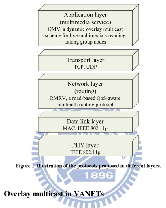
nodes. As shown in Figure 1, we propose OMV for multimedia streaming service in
application layer and in network layer we propose RMRV for packet routing. As to the other
Network layer
(routing)
RMRV, a road-based QoS-aware multipath routing protocol
Application layer
(multimedia service)
OMV, a dynamic overlay multicast scheme for live multimedia streaming
among group nodes
Data link layer
MAC: IEEE 802.11p
PHY layer
IEEE 802.11p
Transport layer
TCP, UDP
Figure 1. Illustration of the protocols proposed in different layers.
1.1
Overlay multicast in VANETs
Infotainment service is a foreseeing trend in VANETs. More and more studies reveal its
feasibility and applicability [2][3][4][5][6][7][8][22]. The delivered infotainment data may be
in a form of messages, files, or multimedia streaming. Multimedia streaming allows
passengers not having to wait for video downloading to finish, and it enables live multimedia
1.1.1.
Live multimedia streaming with overlay multicast in VANETs
This dissertation first considers the scenario of live multimedia streaming among
vehicles of the same group using a dynamic overlay to support application layer multicast.
With live multimedia streaming multicast, passengers in vehicles can join a tour guide’s live
video tour from a source vehicle. For example, in a bus trip that includes several buses, to
save travel expenses, only one tour guide is hired to give live touring in one bus. The
passengers in the rest of buses can view live touring video streaming from the bus with a tour
guide. In this dissertation we focus on live streaming; however, if on-demand streaming is
required, live streaming can be easily extended to support on-demand streaming by
incorporating mechanisms such as retransmission and prefetch.
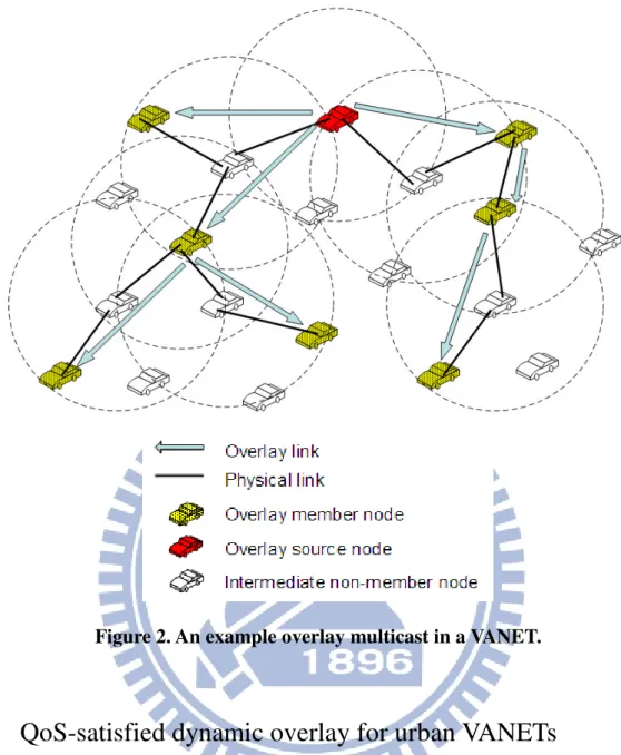
As shown in Figure 2, vehicles interested to join a multicast group can form an
application-layer overlay. The overlay can be organized as a tree or mesh, and the video
streaming source is the root of the overlay. The main advantage using an overlay is that it only
requires group nodes to support the multicast overlay construction and maintenance, which
eliminates the problem of intermediate non-member vehicles’ willingness for cooperation. In
VANETs, we cannot assume that all vehicles support a specific multicast protocol. By using
an overlay that builds logical paths (i.e. overlay links) between group nodes, an advantage is
that the overlay may still work well even if the group nodes are not dense enough. Another
advantage of using an overlay is routing flexibility. Packet delivery among group nodes is
handled by an underlying routing protocol that may cope with a dynamic VANET better.
There has been various routing protocols designed for VANETs [12][13][14][15]. An overlay
Figure 2. An example overlay multicast in a VANET.
1.1.2.
QoS-satisfied dynamic overlay for urban VANETs
Using an overlay for live streaming in urban VANETs, due to that live streaming is
delay-sensitive, the overlay should be able to deliver streams to each group node timely. In
urban VANETs, facing many obstacles and road intersections, the connections between
children nodes and their parents may suffer from frequent disconnections and result in high
packet loss. Therefore, we propose two strategies to enhance the overlay stability: (1)
QoS-satisfied dynamic overlay and (2) mesh-structure overlay. The QoS-satisfied strategy is
proposed to dynamically adjust the overlay to meet its QoS. The mesh-structure strategy is to
As far as we know, only Qadri et al. studied an overlay for multimedia streaming in
VANETs, but they uses a static overlay [1][11][24]. In MANETs, there existed literatures of
dynamic overlays [16][17][18][19][25], but they were not designed for multimedia streaming.
Facing high-mobility, obstacle-prone and broken-link-prone VANETs, they fail to meet the
QoS requirements of multimedia streaming. Therefore, we propose a dynamic overlay for live
multimedia streaming that focuses on QoS in terms of the stream’s packet loss rate and
end-to-end delay. It is a simple and effective QoS-satisfied overlay approach to cope with
high mobility in urban VANETs.
The QoS-satisfied overlay strategy is for a group node to switch to a new parent which
can offer better QoS. This strategy is receiver oriented. To achieve feasible streaming quality,
a low packet loss rate and timely receiving of data packets is required. Therefore, we propose
to use both the stream’s packet loss rate and end-to-end delay to decide whether to switch to a
better parent. Finally, to further ensure packet arrival’s reliability, a two-parent mesh overlay
is constructed. If the route to one parent temporarily fails, the child can still receive streaming
data from the other parent.
In addition, in urban VANETs, there are full of obstacles [13][23][31]. Our simulation
results show that the packet loss rate under large obstacles, such as buildings, can be very
high compared to that under no large obstacles. Therefore, we also investigate a feasible
stream rate and an overlay size for a city map of different road section sizes.
In summary, we propose a dynamic overlay multicast design suited for multimedia
streaming in urban VANETs. To the best of our knowledge, dynamic overlay multicast for
1.2
Routing in urban VANETs
Routing in urban VANETs is quite challenging due to high mobility of vehicles (nodes)
and dense large obstacles, such as buildings. Due to high mobility, communication links may
be broken easily. And dense obstacles limit the radio coverage of a node within a road section,
which degrades node connectivity. As a result, the routes among nodes in VANETs are quite
instable. However, node movements are restricted by the road geometry so that node
movements can be predicted. Besides, vehicle engines can provide unlimited energy for
computation. Nodes may fully utilize the information they learn from each other to obtain
optimal routing decisions. Therefore, routing protocols for VANETs can be well designed to
adapt to the characteristics of VANETs, especially in urban areas.
In urban VANETs, traditional routing protocols are node-based [54][55], while most of
recent routing protocols are road-based [45][46][47][48]. In node-based routing protocols, a
path is composed of selected nodes, and packets are relayed along the determined sequence of
the nodes. However, due to high mobility in VANETs, nodes move apart from each other
easily. The link of two consecutive relay nodes may easily get broken so that route failures
occur frequently in node-based routing protocols. Frequent route failures result in a high
packet loss rate and extra control overhead for route re-discovery. Therefore, road-based
routing protocols were proposed to improve route stability. In road-based routing protocols, a
path consists of a succession of road sections (RSs) from source to destination, and data
packets are transferred along the RSs. Within each RS, geographical forwarding is used.
Geographical forwarding is that upon receiving a packet then a relay node decides its next hop
depending on current neighbor nodes’ positions. The neighbor node currently nearest to the
next RS would be chosen as the next hop. In this way, the choice of a next hop is flexible. As
long as nodes are dense enough in each RS of a path, a data packet can successfully be
RS does not vary too much, in a short period of time. Therefore, road-based routing is steadier
than node-based routing.
To further enhance route stability, multipath routing provides alternative routes
immediately once the current route fails [42][43][49], or provides concurrent transmission
with multiple paths [44]. However, existing multipath routing approaches [42][43][44][49] are
node-based. They still inherit the drawback of frequent routing failure in node-based routing
protocols.
On the other hand, to find the routes with better quality (e.g., higher probability of
connectivity, longer path lifetime, lower packet delay, etc.), some QoS routing approaches for
urban VANETs were proposed [45][51][52][53]. However, most of current QoS routing
protocols for VANETs are node-based, and they only consider scenarios of straight roads (e.g.,
highways) or city roads with limited scope of one or two intersections. For a general city
geometry, road-based routing is more suitable. Recently, IGRP [45] was proposed to utilize
node density and average speed in each RS so as to calculate the probability of connectivity
and hop count, etc., from source to destination. However, it needs an additional traffic
statistics service to obtain the required node density and average speed information.
In this dissertation, we propose a road-based QoS-aware multipath routing protocol for
urban VANETs. Since road-based routing has been shown suitable in urban VANETs
[45][46][47][48], we extend it to find multiple road-based paths. In addition, with multiple
paths available, we propose a QoS path switching scheme to efficiently utilize a better path to
achieve better QoS. Due to node mobility, for each RS in a path, the RS becomes connected
or disconnected as time elapses. Therefore, we propose a space-time planar approach to
predict each RS’s future connectivity in a path, and then proceed to derive a path’s future life
periods. With each path’s future life periods, the source node may dynamically switch to use
QoS. To the best of our knowledge, there is no literature on road-based multipath routing
Chapter 2
Related work
Existing multimedia streaming approaches and routing protocols for urban VANETs are
reviewed in this chapter. We also provide their classifications and comparison tables to
compare different approaches.
2.1
Multimedia streaming approaches for VANETs
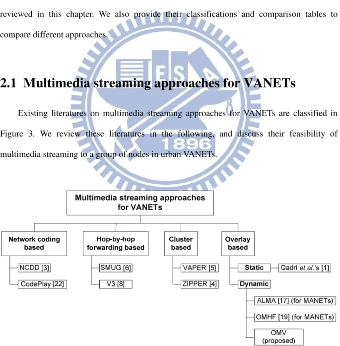
Existing literatures on multimedia streaming approaches for VANETs are classified in
Figure 3. We review these literatures in the following, and discuss their feasibility of
multimedia streaming to a group of nodes in urban VANETs.
2.1.1.
Network coding based streaming
NCDD (Network Coding based Data Dissemination) [3] utilize random network coding
techniques for data dissemination in VANETs. Each group node broadcasts its resource
information to its 1-hop neighbors periodically. In addition, group nodes exchange coded
pieces instead of original pieces. If a coded piece is linearly independent of the coded pieces
in a node's local memory, then the node stores it. A node has to collect enough pieces then for
decoding [2]. Note that network coding based approaches require group nodes periodically
broadcast its collected pieces’ information and retrieves uncollected pieces. Broadcast packets
are not always received by neighbor nodes, and the concurrent transmitting nodes may suffer
from severe collision [4]. Furthermore, network coding based approaches may consume a lot
of time to collect enough pieces to decode if group nodes are not dense enough [4]. Especially
in urban VANETs, due to obstacles, it is difficult for group nodes to hear the broadcasting of
pieces information from one another. CodePlay [22] improves the collision problem of
network coding based approaches (e.g., [2][3]) by adopting a local push scheme that only
selected nodes are allowed to push data packets to other nodes in the same road segment.
However, this technique still did not resolve the problem of group nodes not dense enough.
2.1.2.
Hop-by-hop forwarding based streaming
In SMUG (Streaming Media Urban Grid) [6], a media stream is generated from a certain
point (e.g. a roadside access point), and the stream is fed to SMUG-capable nodes and is
distributed across a VANET [6]. Each node may dynamically be selected as a forwarder, and
its transmissions are scheduled according to a TDMA scheme. Each forwarder is scheduled in
a certain time slot to transmit, and neighboring forwarders would be assigned different time
slots according to the proposed graph coloring technique so as to minimize the chance of
would result in high packet loss, due to hard to meet any forwarder around. Besides, SMUG
can only be applied in TDMA-based ad hoc networks, and it requires all nodes to follow its
specific TDMA channel access scheme.
V3 [8] provides a scheme to retrieve the scene of a certain area to an interested vehicle.
The application scenario of V3 is that for a certain region on the road, the scene can be
captured by one or more video sources, such as pre-deployed stations or vehicles passing by.
The interested vehicles, called receivers, continuously trigger the video sources to send the
videos back. However, this scheme is not suitable for group communications, because each
receiver establishes a path to a source, which is inefficient. Besides, the packet forwarding
protocol in V3 only considers vehicles in a straight road, such as a highway. Therefore, V3 is
not feasible to urban scenarios where a road map has many road intersections.
2.1.3.
Cluster based streaming
Both VAPER (Vehicles Adaptive Peer-to-peer Relay Method) [5] and ZIPPER
(Zero-Infrastructure P2P System) [4] form clusters among vehicles, and multimedia stream
are relayed between clusters. Every vehicle periodically sends a beacon to neighbors to form
clusters. There are a cluster head and also a cluster tail in a cluster. Each vehicle in the same
cluster is one hop neighbor to each other. The main difference between VAPER and ZIPEER
is that VAPER pushes a multimedia stream, while ZIPPER pulls a multimedia stream. In
VAPER, the cluster head broadcasts a multimedia stream to its cluster members, and then the
cluster tail relays the multimedia stream to the cluster head of the subsequent cluster. ZIPPER
assumes a multimedia stream is composed of blocks, and a vehicle can retrieve blocks from
other vehicles if available. If a required block is found, the block would be sent back.
However, both clustering schemes require all vehicles to form clusters and maintain the
stream. And both clustering schemes consider only straight roads, such as highways. They did
not consider urban scenarios where the map has many road intersections. That is, the
clustering schemes can not be directly applied to urban VANETs.
2.1.4.
Overlay based streaming
In overlay based streaming, the source node multicasts a multimedia stream to group
nodes in an overlay. Various kinds of overlay multicast approaches over MANETs have been
proposed [16][17][18][19][25], while in VANETs, only Qadri et al. [1][11][24] discuss video
streaming using a static overlay, as far as we know. Due to high-speed, obstacle-prone and
broken-link-prone characteristics, urban VANETs is very different from MANETs. For
dynamic overlay approaches proposed for MANETs, most of them [16][18][25] aim to
maintain low cost topology in terms of number of overlay links or physical links, but they
cannot adjust the overlay in time for urban VANETs with high mobility. That is, they may
cope with MANETs with low mobility; however, they are not feasible to urban VANETs with
high mobility. Instead of maintaining low cost topology, OMHF [19] and ALMA [17] adjust
an overlay quickly based on current overlay links’ quality. OMHF [19] uses the number of a
node’s link failures to indicate its quality. If a parent’s link quality is lower than its child’s,
their parent-child roles are exchanged. However, OMHF is not suitable for obstacle-prone
urban VANETs. In obstacle-prone VANETs, the new parent may not be able to connect to the
ancestor, and some children may not be able to connect to the new parent. ALMA [17] uses
the overlay link delay as the estimated quality of an overlay link. If the link delay of a child to
its parent exceeds a threshold, the child switches to another parent with shorter link delay.
However, if applying ALMA to urban VANETs, due to high packet loss and frequent
disconnections, a child may switch to a parent with higher packet loss, although the link delay
multimedia streaming in urban VANETs. Feasible multimedia streaming in VANETs needs to
consider the connectivity of children and parents as well as the stream’s packet loss rate and
the end-to-end delay.
As to the related work in VANET, only Qadri et al. [1][11][24] discussed video
streaming using an overlay, as far as we know. They evaluated the feasibility of video
streaming using a static overlay in VANETs, and showed the improvement of applying video
coding and error resilience. However, the overlay structure was static, even though nodes are
mobile, which may suffer from inefficient overlay structures and frequent disconnections. In
our work, we focus on dynamic overlay adaptation. In Table 1 the aforementioned approaches
are compared, considering the feasibility of multimedia streaming for a group of nodes in
urban VANETs.
Table 1. Comparison of existing multimedia streaming approaches for VANETs.
Hop-by-hop forwarding
based Overlay based
Approach V3 [8] SMUG [6] Network coding based [2][3][22] Cluster based [4][5] Qadri et al.’s [1] ALMA [17] OMV (proposed) Basic idea Continuously trigger and reply between a receiver and the source Scheduled multicast Network coding coded packets are exchanged among members Nodes form clusters, and packets are relayed between clusters Static mesh overlay (only 7 nodes) 1. Dynamic tree overlay 2. Overlay is adjusted according to overlay link delay (designed for MANETs) 1. Dynamic tree / mesh overlay 2. Overlay is adjusted according to packet loss rate and end-to-end delay Suitable for obstacle-prone environments (eg. urban)
No Yes No No Yes Yes Yes
Required density
of group nodes High Medium Medium High Low Low Low
QoS supported No No No No No No Yes
Obstacles
2.2
Routing protocols in urban VANETs
Existing routing protocols for urban VANETs are classified as Figure 4. The routing
approaches of each category are reviewed in the following subsections.
Routing protocols for
urban VANETs
Multipath routing Single-path routing QoS routing LOUVRE [47] FROMR [43] AOMDV [42] Road-based Node-based IGRP [45] GyTar [46] QosBeeVanet [51] VOA [52] MURU [53] RBVT [48] RMRV (Proposed) DDR [49] Node-based Road-based Road-based Node-based GPCR [55] GPSR [54]Figure 4. Classification of routing protocols for urban VANETs.
2.2.1.
Road-based vs. node-based routing
In literatures of routing protocols for urban VANETs, vehicles are assumed to be
equipped with GPS (global positioning systems) and street-level city maps [45][46][47][48].
With GPS, each node knows its own and its neighbors’ positions, and may utilize the position
information to forward data packets toward destination [54][55]. These kind of routing
protocols are node based. However, due to dense obstacles in city maps, sometimes a routing
path may fail to be found. Therefore, road-based routing protocols are proposed. GyTar
road-based routing protocol. A relay node computes the score of each neighboring road
intersection, and decides the next road intersection to forward packet to. The score is decided
by the node density and road distance to the destination. However, GyTar is a greedy
algorithm so that the current chosen road intersection may later lead to road sections with
poor node density and connectivity.
LOUVRE (Landmark Overlays for Urban Vehicular Routing Environments) [47] builds
an overlay on top of an urban topology [47]. The overlay consists of connected roads in the
topology. To form an overlay, LOUVRE uses a P2P protocol for discovering and distributing
traffic density information of each road among all nodes in a network environment. Each node
exchanges traffic density information with its neighbors via broadcasting. Then, a path
between a source and a destination on the overlay can be found by using Dijkstra’s algorithm.
However, the scalability of the overlay is limited due to P2P exchange delays in the network
environment.
The RBVT (Road-Based using Vehicular Traffic) routing protocol [48] creates a
road-based path consisting of a succession of road intersections [48]. The authors proposed a
reactive protocol, RBVT-R and a proactive protocol, RBVT-P. The route discovery scheme in
RBVT-R is similar to the traditional source routing protocol, but the routing information
piggybacked in a packet is a succession of road intersections instead of nodes. RBVT-P is
similar to LOUVRE. Nodes periodically discover and disseminate the road-based network
topology to maintain a global view of the network connectivity. The performance of RBVT-R
depends on the stability of every RS’s connectivity, and the performance of RBVT-P depends
2.2.2.
Multipath routing
There is no existing road-based multipath routing protocol for VANETs, as far as we
know. In the following, we review existing node-based multipath routing protocols for urban
VANETs. AOMDV [42], extended from AODV [59], is a representative multipath routing
protocol for MANETs. If it is applied to VANETs, due to high mobility, link lifetimes to next
hops expire soon, thus an alternative route may still fail at a certain relay node. FROMR (Fast
Restoration On-demand Multipath Routing) [43], which is a node-based routing protocol,
extends AODV to discover multiple paths so as to rapidly build an alternate path if the current
route fails. Unlike AODV where duplicate copies of RREQ messages are simply discarded,
FROMR uses some of these copies to form multiple reverse paths. In addition, to reduce
control overhead, FROMR partitions a geographic region into grids and assigns each grid a
grid leader. Only leaders are responsible for control messages broadcasting and data
forwarding. Although FROMR provides more choices of next hops, in essence the link
lifetimes of these next hops still expire soon, due to high mobility in VANETs. DDR
(Differentiated Reliable Routing) [49] is also a multipath routing protocol in hybrid VANETs,
which have road side units (RSUs). In hybrid VANETs, a multi-hop path may include RSUs
as intermediate nodes for packet relaying.
2.2.3.
QoS routing
Most of existing QoS routing protocols in VANETs are node-based. QoSBeeVanet [51]
imitates honey bees’ behavior to find a route with better QoS in VANETs. VOA [52] assumes
a highway scenario. It selects an optimal routing path and backup routing paths in order to
gracefully switch to a backup routing path before the current routing path is broken. MURU
[53] uses an expected disconnection degree (EDD) to estimate a probability that a route will
only utilizes local map information and it may lead to the local optimum problem.
IGRP (Intersection-based Geographical Routing Protocol) [45] is a road-based single
path QoS routing protocol. In IGRP, a path is composed of a succession of road sections (RSs).
Therefore, a path’s QoS may be estimated with the QoS of RSs. IGRP first retrieves the node
density and average node speed of each RS using an existing location service. Then, these
data are utilized to probabilistically estimate QoS related metrics, such as probability of
connectivity, end-to-end delay, hop count, and bit error rate (BER). Therefore, for paths
between source and destination, only the path that satisfies the constraints of these metrics is
selected.
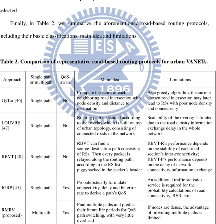
Finally, in Table 2, we summarize the aforementioned road-based routing protocols,
including their basic classifications, main idea and limitations.
Table 2. Comparison of representative road-based routing protocols for urban VANETs.
Approach Single path or multipath
QoS-
aware Main idea Limitations
GyTar [46] Single path No
Compute the score of each neighboring road intersection with node density and distance to destination
As a greedy algorithm, the current chosen road intersection may later lead to RSs with poor node density and connectivity
LOUVRE
[47] Single path No
Routing path is decided according to the overlay which is built on top of urban topology, consisting of connected roads in the network
Scalability of the overlay is limited due to the road density information exchange delay in the whole network
RBVT [48] Single path No
RBVT can find a
source-destination path consisting of RSs. Then every packet is relayed along the routing path, according to the RS list
piggybacked in the packet’s header
RBVT-R’s performance depends on the stability of each road section’s intra-connectivity; RBVT-P’s performance depends on the delay of network
connectivity information exchange
IGRP [45] Single path Yes
Probabilistically formulate connectivity, delay and bit error rate to derive a path’s QoS
An additional traffic statistics service is required for the probability calculations of road connectivity, BER, etc. RMRV
(proposed) Multipath Yes
Find multiple paths and predict their future life periods for QoS path switching, with very little overhead
If nodes are dense, the advantage of providing multiple paths is limited
Chapter 3
Proposed dynamic overlay multicast for
live multimedia streaming in urban
VANETs
3.1
Overview of the proposed overlay multicast in
VANETs (OMV)
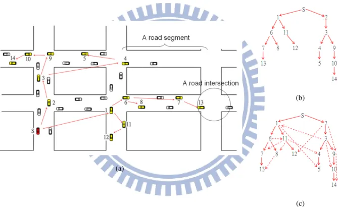
This chapter considers the scenario of live multimedia streaming multicast to vehicles of
the same group, and these group-member vehicles are organized as an overlay tree, as shown
in Figure 5(a) and Figure 5(b). Group-member vehicles (called group nodes or overlay nodes,
interchangeably) join the multicast tree initiated by a vehicle which is a streaming provider;
this vehicle acts as the multicast source node. Multimedia packets generated by the multicast
source node are delivered along the overlay tree. The link between a parent and its child may
be actually a multiple-hop path through intermediate non-member nodes, which is referred as
an overlay link. In an overlay link, packets are passed using the underlying network-layer
routing protocol. The source node also plays the role of the bootstrap node (BSN) of the
multicast tree. When a node wants to join the multicast tree, it firstly asks the BSN for which
node to be its parent, so as to become a member of the tree.
As vehicles move rapidly, an overlay tree need to change its structure to maintain QoS.
going far way from its parent node 3 and child node 5. Such a situation will result in high
packet loss and long packet delay in the overlay. Therefore, we propose to dynamically adjust
the overlay to maintain its QoS. In addition, to further enhance the robustness of an overlay,
we build a two-parent overlay, as shown in Figure 5(c). We propose this dynamic overlay (i.e.
QoS-satisfied dynamic overlay and two-parent overlay) to suit for live multicast streaming
scenarios, so that passengers in group-member vehicles can enjoy live reliable video
streaming from the source vehicle.
(b)
(a)
(c)
Figure 5. An illustration of a multicast overlay in urban VANETs: (a) an overlay formed
by interested vehicles, in urban roads; (b) the corresponding overlay tree; (c) expanding the
3.2
Proposed overlay construction and QoS-satisfied
overlay adaptation
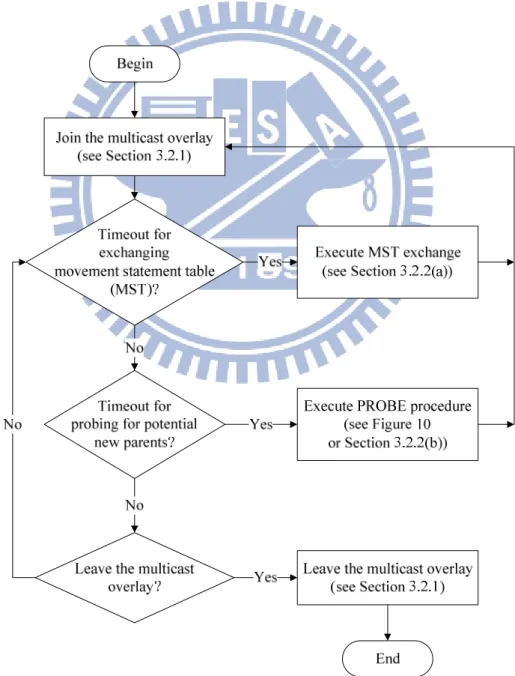
In the following, we introduce the proposed overlay construction and QoS-satisfied
overlay adaptation. Firstly, we present the life cycle of a group node in a multicast overlay in
Figure 6. The life cycle of a group node includes joining the multicast overlay, periodically
exchanging its movement state table with other group nodes, dynamically adjusting its parent,
and finally choosing to leave the multicast overlay.
3.2.1.
Join and leave
As mentioned previously, the streaming source node also acts as the BSN of the
multicast tree. The BSN has an overlay structure table which records the current successfully
joined nodes, their coordinates, and their children. The purpose of maintaining the overlay
structure table in the BSN is to select a candidate parent for a new node requesting to join the
multicast overlay. Besides, the BSN periodically broadcast its node ID to other nodes
interested in joining the group so that the node ID of the BSN is available to all interested
nodes. When a node requests to join an overlay, the join procedure is executed, which
includes five stages: (1) a requesting node sends a JOIN request to the BSN to ask which node
to be its parent. (2) Then, from the BSN’s overlay structure table, the BSN chooses a node as
the candidate parent and replies to the requesting node. A node in the same road section as the
requesting node is the best choice as its parent; otherwise, the node nearest to the requesting
node would be chosen. (3) When the reply from the BSN is received, the requesting node
sends a JOIN_PARENT request to the candidate parent. The candidate parent will accept it if
its number of children does not exceed a given maximum number of children
(MAX_CHILDREN). (4) If the JOIN_PARENT request is rejected, the requesting node asks
the BSN again and executes the join procedure (2) ~ (4) until it successfully finds a parent. (5)
When the requesting node successfully joins the parent, it then informs the BSN to update the
overlay structure table. Note that in step (4), the requesting node also informs the BSN of the
candidate parent that it failed to join. Then in step (2), the BSN would avoid choosing this
candidate parent.
Note that there is a situation that rarely happens in MANETs, but we found it common in
urban VANETs. The earlier successfully joined nodes may be forced to accept too many
children nodes. Due to route discovery being more difficult in urban VANETs, it often takes 5
candidate parent. Much time is wasted in request retries. This situation not only relates to end
user satisfaction, but it may cause imbalance load. That is, when an interested node requests
to join the multicast overlay, it usually takes long time to complete the join procedure in urban
VANETs. As a result, the earlier successfully joined nodes may be forced to accept too many
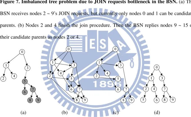
children nodes. Figure 7 shows an example of an imbalanced tree. Assume node 0 is the BSN.
The node number is assigned according to the order of the BSN receiving the corresponding
node’s JOIN request. For example, node 3 is the third node that the BSN receives a JOIN
request. A dotted node means that it has not finished the join procedure. Initially, node 1
successfully joined node 0. At this time, only nodes 0 and 1 can be candidate parents. Then, in
a short duration, the BSN receives nodes 2 ~ 9’s JOIN requests. And the BSN replies each
requesting node a candidate parent of node 0 or node 1, except for node 9 because the
children number of either nodes 0 and 1 has reached MAX_CHILDREN (e.g., 4). Node 9 has
to wait for a new candidate parent. As the BSN is handling the JOIN requests, nodes 2 and 4
finish the join procedure, as shown in Figure 7(b). At the same time, the BSN has received
nodes 10 ~ 15’s JOIN requests. So the BSN replies nodes 9 ~ 15 that their candidate parent
are nodes 2 or 4. Note that node 0 and node 1 cannot be candidate parents because they have
reached MAX_CHILDREN. Therefore, as we can see, the earlier successfully joined nodes
may be forced to accept too many children nodes. This is due to that it takes long time for a
node to finish the join procedure, and by then there may have several arrived nodes waiting
for joining the overlay.
A solution is as follow. Regardless of requesting nodes successfully joining the given
candidate parents or not, all requesting nodes can be used by the BSN as other nodes’
candidate parents so as to increase the number of available candidate parents, as shown in
Figure 8(a). However, in urban VANETs, route failures are common. For example, node 5
cannot start the multimedia streaming service. To conquer this, we propose a simple and
effective solution. We allow the BSN to provide two candidate parents to a child at once in
stage (2) of the JOIN procedure. The resulting overlay structure is shown in Figure 8(b),
which is a two-parent mesh overlay. In this way, a requesting node has higher possibility to
join a parent successfully. For a tree overlay, when a requesting node successfully joins one of
the candidate parents, the JOIN request to the other candidate parent will be canceled. Figure
8(c) shows the final tree, and is redrawn as shown in Figure 6(d). Thus, the imbalanced tree
problem is resolved, and the join delay is shortened as well.
Finally, when a node wants to leave the multicast tree, it sends a LEAVE message to its
neighbors so as to handover its children to its parent. The LEAVE message lists the leaving
node’s children’s IDs and its parent’s ID. The format of the LEAVE message is <node ID,
parent’s ID, number of children, child 1’s ID, child 2’s ID, …>, so that each child knows its
new parent, and the parent knows its new children. Note that to avoid a leaving node’s parent
from becoming overloaded, the leaving node’s parent will only accept new children up to its
maximum number of children (MAX_CHILDREN). The leaving node’s parent accepts new
children that are close to it based on its movement state table. For those children not accepted
by the leaving node’s parent, they will find their new parents via a parent selection procedure,
called PROBE. The detail of the PROBE procedure is described in the following Section
(a) (b)
Figure 7. Imbalanced tree problem due to JOIN requests bottleneck in the BSN. (a) The
BSN receives nodes 2 ~ 9’s JOIN requests, but currently only nodes 0 and 1 can be candidate
parents. (b) Nodes 2 and 4 finish the join procedure. Then the BSN replies nodes 9 ~ 15 of
their candidate parents as nodes 2 or 4.
6 0 1 3 2 4 5 7 9 8 (a) (b) (c) (d)
Figure 8. Solution to the imbalanced tree problem, as shown in Figure 7(a). (a) All
requesting nodes are allowed to be assigned by the BSN to be candidate parents. Note that
join failure of a whole subtree may occur, such as node 5 and its descendants. (b) In addition
to (a), let the BSN provide two candidate parents to a child at once. (c) The candidate parent
which is slower to finish the join procedure will be released. (d) We have a more balanced
3.2.2.
QoS-satisfied overlay adaptation
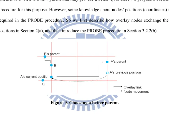
To dynamically adjust an overlay structure so as to maintain a low packet loss rate, we
propose a QoS-satisfied overlay adaptation mechanism by choosing a better parent
dynamically. An example is shown in Figure 9. Assume node A moves far away from its
parent, resulting in frequent packet loss. At this time, node B is close to node A. Node B may
be more appropriate to be node A’s new parent. And so does node C. Node A has to decide
whether to switch to a new parent that may provide a better QoS. Here we propose a PROBE
procedure for this purpose. However, some knowledge about nodes’ positions (coordinates) is
required in the PROBE procedure. So we first describe how overlay nodes exchange their
positions in Section 2(a), and then introduce the PROBE procedure in Section 3.2.2(b).
Figure 9. Choosing a better parent. (a) Movement state table exchange
In the proposed OMV, each overlay node maintains a movement state table (MST) that
records the movement state of each overlay node. A movement state contains <nodeID, x, y,
parent’s ID, timestamp>, where x and y are coordinates of node nodeID obtained by GPS.
Each overlay node periodically exchanges its MST with its overlay neighbors. Note that each
overlay node only exchange MSTs with its overlay neighbors so as not to incur too much
traffic load. Before a node sends its MST to its neighbors, it refreshes its own movement state
with the received MST.
(b) Probing for a new parent
As shown in Figure 9, node A may have multiple potential new parents. A new parent with
low packet loss and low end-to-end delay is most preferred. In the following, we propose a
PROBE procedure to decide whether to switch to a new parent for better QoS. Note that to
reflect the correct packet loss rate of a node, the calculation of the packet loss rate only bases
on the duration from the time the node switching to its current parent to the current time. In
addition, for live streaming, each node has a playout buffer. Thus, we define the packet loss
rate of nodei as:
Let t = the time when nodei switched to its current parent.
Dri(t)= non-duplicate data bytes nodei received, from time t to the current time tc. Packets not
arriving within playout buffer time are discarded.
Ds(t) = data bytes of the stream, from time t to the current time tc. Thus Ds(t) = source stream
rate × (tc – t).
Therefore, the packet loss rate ri of nodei is 1 - Dri/Ds.
For example, supposing the source stream rate is 128 kbps. If nodei switched to its current
parent at time 100 s, and nodei receives a PROBE request at time 120 s, then Ds = 128 kbps ×
(120 s – 100 s) = 320,000 bytes. Supposing during this period of 20 s, nodei has received
240,000 bytes, then nodei’s packet loss rate = 1 - 240,000/320,000 = 0.25.
We also calculate the end-to-end delay for each overlay node. The end-to-end delay is
the average time taken for a data packet to be transmitted from the source node to an overlay
node. Note that the calculation of end-to-end delay only bases on the duration from the time a
node switching to its current parent to the current time. In addition, there is no retransmission
for packet loss, since we focus on live streaming. Duplicated data packets and data packets
end-to-end delay is used to examine that if an overlay node switches to a new parent, whether
the associated end-to-end delay, from the source to the new parent to the overlay node can
meet the playout buffer time requirement. In this way, a node will not select a new parent such
that the node’s end-to-end delay exceeds the playout buffer time.
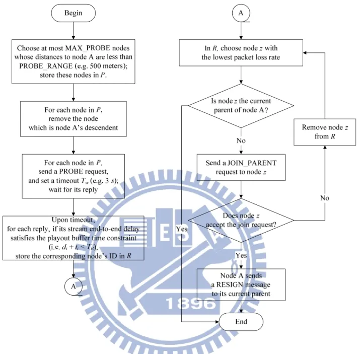
Proposed PROBE procedure
As shown in Figure 10, assume that node A is to execute the PROBE procedure. From the
MST, node A knows the other nodes’ positions and which nodes are its descendants. From
node A’s MST, node A chooses the nodes which are within the distance threshold
PROBE_RANGE (e.g. 500 meters) fromnode A. These nodes form a set P, such that size(P)
≤ MAX_PROBE. Note that the nodes near to node A would be chosen first. In addition, to
avoid forming loops, the nodes which are node A’s descendants would be removed from P.
Then, node A sends a PROBE request to each node of P. Afterward, node A sets a timeout of
TW and wait for nodes in P to reply. For each node i that has received a PROBE request, it
replies node A with its packet loss rate ri, and its end-to-end delay di. Note that by GPS the
clocks of all nodes can be synchronized. Therefore, the overlay link delay ti, which is the
delay from node i to node A, can be calculated using the timestamp in a PROBE reply packet.
During TW, node A may receive multiple replies from nodes of P. These nodes form a set R.
We pick up the nodes from R such that the resulting end-to-end delay (di + ti) can meet
playout buffer time TB for node A. These nodes form a set R’. That is, R’ = {xi | di + ti < TB,
∀xi∈R}. Finally, we select the node z with the lowest packet loss rate from R’ to be the
candidate parent of node A. Then, node A sends a JOIN_PARENT to node z. If node z accepts
the offer, node A sends a RESIGN message to node A’s current parent. If node z rejects the
offer, node A removes node z from R’ and chooses another node with the next lowest packet
will not take any action.
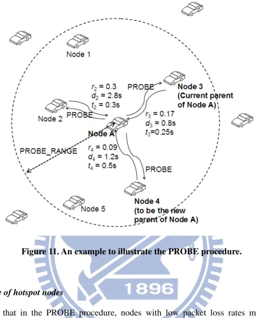
Figure 11 uses an example to illustrate the PROBE procedure. Node A looks up its MST
and found 5 nodes (nodes 1 ~ 5) are within PROBE_RANGE to itself. Assume
MAX_PROBE is 3; thus, only three nodes would be chosen for probing. Therefore, nodes 2, 3,
4 will be chosen because they are closer to node A than nodes 1 and 5. Node A sends a
PROBE request to each of these nodes. Then, each of them replies its packet loss rate ri and
end-to-end delay di. The overlay link delay ti is also known using the timestamp in the
PROBE reply packet. Assume the playout buffer time TB is 3 s. For nodes 2, 3 and 4, node 2
cannot meet playout buffer time constraint, due to that d2 + t2 > TB. Therefore, node A discards
node 2. As to nodes 3 and 4, node 4 has a lower packet loss rate than that of node 3. Therefore,
node A changes it parent to node 4 by sending a JOIN_PARENT to node 4.
Notice that a node’s packet loss rate results from its parent’s packet loss rate as well as the
parent-child link loss rate. The parent’s packet loss rate is addressed explicitly in the proposed
PROBE procedure. In addition, the parent-child link loss rate is addressed implicitly in the
PROBE procedure. If a child can successfully receive a PROBE reply from a probed parent
before PROBE timeout, it implies that the associated parent-child link is reliable and has a
Figure 11. An example to illustrate the PROBE procedure.
Avoidance of hotspot nodes
Note that in the PROBE procedure, nodes with low packet loss rates may be more
probable being selected as parents and may become hotspot nodes. Therefore, we set an upper
bound (MAX_CHILDREN) of the number of children for a node. In addition, as a node
accepting more children, its packet loss rate will increase due to more traffic load. As a result,
the occurrence of hotspot nodes can be minimized.
Loop-free tree overlay
The loop problem may occur in an overlay due to two conditions: (1) a node chooses its
descendant as its parent, or (2) two nodes simultaneously choose each other or each other’s
descendant as their parents [17]. For a tree overlay, these two conditions also result in network
avoided in the proposed PROBE procedure. This is because a node always tries to switch to a
new parent with low packet loss rate, which makes the overlay formed a minimum heap. That
is, the packet loss rate of a node is lower than that of its descendants, in a minimum heap.
Thus, for condition (1), a node would not choose any of its descendants as its parent, since the
packet loss rates of the descendants are higher than that of the node. In addition, as mentioned
previously in the PROBE procedure, a node will not choose its descendants and send them
probe requests. This is to avoid loops and also not to waste time to probe for descendants. As
to condition (2), in a minimum heap, for any node x, assuming node x chooses a new parent
node y, this implies that the packet loss rates of node y and the ancestors of node y are lower
than those of node x and those of node x’s descendants. Consequently, neither node y nor the
ancestors of node y would choose node x or node x’s descendants as parents. That is,
condition (2) would not happen in the PROBE procedure. In summary, the proposed tree
overlay is a loop-free overlay, and it will not suffer from network partitions.
3.2.3.
Two-parent overlay
The disconnection of any overlay node from its parent in a tree overlay leads to its entire
offspring disconnected, which would result in severe performance degradation, especially in
urban VANETs. In this dissertation, we use a mesh overlay to enhance the tree overlay. We
adopt a two-parent overlay. Each node in an overlay may have two parents. If the route to one
parent fails, the child can still receive streaming data from the other parent. For the mesh
overlay, the procedures of MST exchange and PROBE are basically the same as those of the
tree overlay. However, one thing is different from the tree overlay. In the PROBE procedure
for the mesh overlay, if a node is going to replace its current parent with a better parent, the
node does not resign the current parent immediately. The current parent is set as a “supporting
MST exchange and run the PROBE procedure. The purpose of the supporting parent is that if
some stream is not received by the main parent, the child can still receive lost packets from
the supporting parent. Duplicate packets will be discarded. If later the PROBE procedure
finds a better parent, the supporting parent will be discarded, and the main parent will become
a supporting parent. Finally, for the case of an overlay allowing more than two parents, our
scheme is still workable: one main parent and the others are supporting parents. However, an
overlay with too many parents is inefficient, due to too many duplicate data. In VANETs, we
adopt two parents for a child in an overlay for a better packet loss and duplication data. Since
main parents execute the proposed PROBE procedure, the tree formed by main parents is
loop-free, as explained previously. Thus, the proposed mesh overlay would not suffer from
network partitions.
3.2.4.
Detection of a node unexpected leaving or a node disconnected
from its parent
If a node unexpectedly leaves the overlay, or a node is disconnected from its parent, the
overlay can be repaired by the PROBE procedure, as described in Figure 10. The PROBE
procedure is periodically invoked. Therefore, for nodes disconnected from their parents, or for
the children that their parent unexpectedly left, they will find new parents in the PROBE
procedure.
3.2.5.
Summary of our OMV features for urban VANETs
To adapt to urban VANETs, the proposed OMV scheme has the following features:
(1) Avoiding imbalanced load in the overlay structure: The earlier successfully joined