Design and Implementation of the SNMP Agents
for Remote Monitoring and Control via UML
and Petri Nets
Jin-Shyan Lee and Pau-Lo Hsu, Member, IEEE
Abstract—For large-scale and long-distance distributed sys-tems, this paper proposes a systematical multiparadigm approach to develop the simple network management protocol (SNMP) agents for remote monitoring and control. The standard unified modeling language (UML) is adopted for modeling the system, and then the Petri-net model is applied to achieve both qualitative and quantitative analyses for the system’s dynamic behavior. In real applications, the present design can be further implemented with Java and ladder diagrams on programmable logic controllers (PLC). The developed system has been used successfully in a mobile switching center (MSC) of Taiwan Cellular Corporation for the remote monitoring and control, through the Internet, of its environmental conditions, including the temperature, humidity, power, and security, with a total of 316 sensors and 140 actuators. Index Terms—Java, Petri nets (PNs), programmable logic controllers (PLC), remote monitoring and control, simple network management protocol (SNMP) agents, unified modeling language (UML).
I. INTRODUCTION
F
OR many automated manufacturing processes in large-scale and long-distance distributed systems, the remote monitoring and control system is crucial to achieving guaran-teed normal operations. It allows for monitoring the status of processes, detecting abnormal conditions, activating emergency machines, and reporting alarms. In the traditional approach, people are often put at risk monitoring industrial processes in close proximity through a specific network protocol. Recently, due to the rapid development of Internet technology, monitoring systems no longer needs to be within a given area, and several remote approaches have been proposed that allow people to monitor the processes of manufacturing systems from great distances [1]–[5].In general, the components of remote monitoring and control systems can be classified as either: 1) agent side or 2) manager side. Since some device vendors are beginning to build web server software into their agent-side devices, the manager-side users can monitor these devices directly using web browsers through the hypertext transfer protocol (HTTP) [1]–[4].
How-Manuscript received April 10, 2003. How-Manuscript received in final form July 1, 2003. Recommended by Associate Editor P. Mosterman. This work was supported in part by the National Science Council, R.O.C. under Grant NSC 90-2213-E-009-101 and in part by the MOE Program for Promoting Academic Excellence of Universities under Grant 91-E-FA06-4-4.
The authors are with the Department of Electrical and Control Engineering, National Chiao-Tung University, Hsinchu 300, Taiwan, R.O.C. (e-mail: plhsu@ cc.nctu.edu.tw).
Digital Object Identifier 10.1109/TCST.2004.824287
ever, as more and more devices are networked in automated manufacturing systems, managing information on all of theses devices becomes increasingly difficult. The overall system needs a mechanism not only to monitor its devices but also to effectively manage them. One approach to manage diverse network elements is to use the simple network management protocol (SNMP), a standard protocol now widely supported by device vendors for their products such as routers, bridges, and printers [5], [6]. However, in real industrial applications, many basic and major components such as sensors, motors, and programmable logic controllers (PLC) still do not support SNMP for remote applications. Therefore, this paper presents a systematic design approach to embed SNMP agents into remote devices so as to achieve remote monitoring and control through a standard network protocol.
The unified modeling language (UML) is a language for specifying, constructing, visualizing, and documenting the elements of a software-intensive system [7]. It defines the no-tation and semantics to describe systems using object-oriented and meta-modeling concepts in the spirit of the multiparadigm modeling [8]. Each model in the UML describes one aspect of a system, and the combination of the various models adequately describes the entire system. However, although UML is con-venient for modeling a complex system, UML is not equipped with the necessary techniques for analyzing a system’s qualita-tive and quantitaqualita-tive properties [9]. One of the major problems in using UML for the formal specification of systems is that the semantics of UML are imprecise and vague. Particularly, the UML has no execution semantics and the current behavioral specifications in UML are primitive. UML also lacks tools and analysis support for behavioral models [9]–[11]. On the other hand, the Petri net (PN) is a graphical-mathematical tool used to model and analyze various systems, especially for systems with parallel and concurrent activities [12]–[16]. PN provides qualitative analysis for system properties such as reachability, liveness, boundedness, and conservativeness. Moreover, by introducing time functions into the PN to form a timed PN, quantitative analysis can then be performed [14], [15]. PN complements the UML in a number of ways. First, it provides a powerful and rich visual formalization for specifying behavior in general, and concurrent behavior in particular. Second, it provides an executable notation, something that UML currently lacks. Statechart is the model that most closely resembles PN in the UML. However, Statechart describes state machines that are finite state systems whereas PN can be extended to present infinite state systems. Furthermore, PN has, in contrast
Fig. 1. The systematic development procedure for SNMP agents.
to UML Statechart, precise semantics and powerful analytical methods [14], [15]. This is why, in this paper, the PN is adopted to obtain a dynamic and analyzable model for large-scale and long-distance distributed systems. With this approach, both qualitative and quantitative analyses can be applied to achieve reliable remote monitoring and control.
As mentioned above, a remote monitoring system consists of the agent and manager sides. The present approach develops SNMP agents based on the UML modeling with PN analysis. As shown in Fig. 1, the use-case diagram and sequence diagram in UML are used to capture the SNMP requirements corresponding to the monitoring and control specifications at the stage of functional and interactive analyses. Then, at the stage of static structural modeling, the class diagram is applied to describe the static relationships of the system. Subsequently, the PN model is constructed according to the above models such that both qualitative and quantitative analyses of the system’s dynamic behavior can be performed. Finally, at the architectural design stage, the deployment diagram is modeled to capture the physical relationships among software and hardware components, and the obtained models are implemented using Java and ladder dia-grams on the industrial PLC [17], [18]. The design procedure in Fig. 1 is a type of “round-trip” engineering, in which all models may be developed in an iterative and incremental way through a repeated cycle of analysis, design, implementation, and testing. Therefore, the proposed approach is quite flexible and it allows making some alterations, such as changing the requirements or fixing a design flaw. A case study of an environmental monitoring system for the mobile switching center (MSC) is provided in this paper to illustrate the proposed approach.
II. REQUIREMENTS OFSNMP AGENTS
The SNMP is an application-level protocol that offers network management services in the transmission-control protocol/internet protocol (TCP/IP) suite [6]. It is based on a client/server relationship in which the client issues requests to
but unsolicited information (e.g., the alarm conditions) to the management station in the monitoring and control center.
In the management station as shown in Fig. 2, three basic types of SNMP messages are issued on behalf of a management application:
• GetRequest; • GetNextRequest; • SetRequest;
where the first two are variations of the get function. All three messages are transmitted with protocol data units (PDU) and ac-knowledged by the agent in the form of GetResponse message passed to the management application. In addition, an agent may issue a trap message in response to an event that affects the MIB and the underlying managed resources. Since SNMP relies on user datagram protocol (UDP), which is a connection-less protocol and has high transmission efficiency for small data packets, SNMP is itself connectionless. No ongoing connec-tions are maintained between a management station and agents. Moreover, in the standard SNMP, since traps from the agent are not acknowledged by the manager, there must be a mech-anism to ensure that conditions in devices requiring attention are not missed. Therefore, we further design and implement the following two messages based on SetRequest to respond to the following traps:
• TestRequest; • TrapAck.
When an alarm condition occurs, the designed SNMP agent will send the corresponding trap message to the manager periodi-cally. The TestRequest message is used to check the alarm con-ditions in order to avoid false alarms, while the TrapAck mes-sage is used to confirm alarms. When an alarm is reported to the manager, the manager may use TestRequest to reset the alarm. If the physical input for such an alarm is still high, the same alarm trap message will be sent again. On the other hand, after an alarm trap is sent, the manager may use the TrapAck message to confirm the alarm and the SNMP agent will then be disabled to send the same trap message periodically.
Two major advantages are obtained due to the utilization of SNMP for remote monitoring and control as follows.
1) Delocalization of the monitoring stations: the manage-ment stations can be arbitrarily located anywhere through the Internet. Also, integration of a large number of moni-toring devices in a given station becomes possible. 2) Ease of Access: the remote manager can access the local
Fig. 2. The simple network management protocol (an extension of [6]).
Fig. 3. Functional analysis with the use-case diagram.
III. UML-BASEDMODELING FORSNMP AGENTS
In the proposed approach, UML modeling and PN analysis are used to develop SNMP agents for remote monitoring and control. Then, the Java language and ladder diagrams are adopted to implement the system on an industrial PLC practically.
A. Functional Analysis With the Use-Case Diagram
A use-case diagram is used to capture the basic functional requirements of the system. As shown in Fig. 3, it consists of three actors and nine use cases. The actors, drawn as stick figures, represent users and other external systems that interact with the described system. The use cases, drawn as ellipses, represent the scenarios of the system. A scenario is a sequence of steps describing interaction between a user and a system.
Basically, an SNMP Manager can perform the following five use cases: • GetRequest; • GetNextRequest; • SetRequest; • TestRequest; • TrapAck;
where GetNextRequest is an extension of GetRequest;
TestRe-quest and TrapAck are specialized from SetReTestRe-quest. Any one of
the above five requests will cause the SNMP Agent to carry out
HandleRequest, including GetResponse, to result in a response
to the request. On the other hand, as soon as Managed
De-vice lies in the AlarmCondition, the SNMP Agent will perform SendTrap to report the alarms. Then, the SNMP Manager can
carry out TestRequest to check the alarm conditions in order to avoid false alarms, and may perform TrapAck to confirm the alarm and then take the necessary control actions.
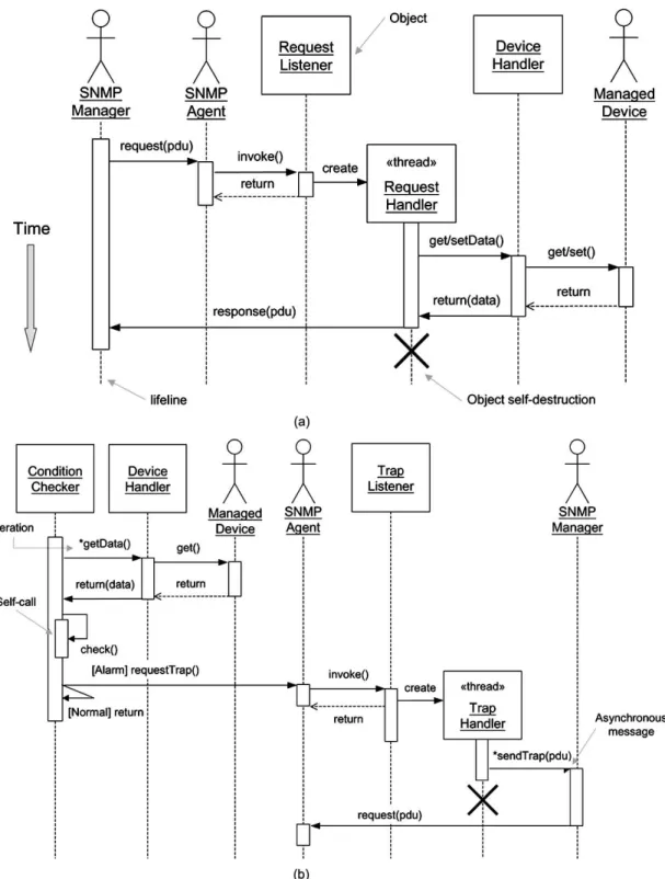
Fig. 4. Interaction analysis with the sequence diagrams for (a) the Request scenario and (b) the Trap scenario.
B. Interactive Analysis With the Sequence Diagram
A sequence diagram shown in Fig. 4 is used to model the object interaction in a system. Whereas the use-case diagram enables modeling of scenarios, the sequence diagram indicates details of the scenario including the objects and classes used to implement the scenario and messages passed between objects. Within a sequence diagram, an object is shown as a box at the top of a vertical dashed line, called the object’s lifeline, repre-senting the life of the object during the interaction. Messages
are represented by horizontal arrows and are drawn chronolog-ically from the top of the diagram to the bottom.
Fig. 4(a) shows the sequence diagram for the Request sce-nario, which includes the five types of requests (GetRequest,
GetNextRequest, SetRequest, TestRequest, and TrapAck)
de-scribed in the use-case diagram in Fig. 3. At the first stage, the
SNMP Manager may send a request to the SNMP Agent. Then,
the SNMP Agent will invoke the Request Listener to create a threaded object, Request Handler, to carry out the request. The
Managed Device through the Device Handler, and then sends
a response to the SNMP Manager. After finishing the request, the threaded object Request Handler will delete itself so as to release resources for the system.
For the Trap scenario as shown in Fig. 4(b), the Condition
Checker iteratively scans the status of the Managed Device
through the Device Handler and checks its condition (the asterisk indicates the iteration in UML). If the condition is un-desirable or faulty, Condition Checker will send a requestTrap message to the SNMP Agent. Then, SNMP Agent will invoke the Trap Listener to create a Trap Handler, a threaded object, which carries out the request. The Trap Handler sends the trap to SNMP Manager asynchronously (the half-arrowhead symbol indicates an asynchronous message in UML) and then deletes itself to release the resources for proceeding use. When SNMP
Manager receives the trap message, it will send a request of TestRequest to check the alarm condition, or perform TrapAck
to confirm the alarm.
IV. REMOTEMONITORING ANDCONTROL OF ANMSC
A. Description of a Mobile Switching Center
In wireless cellular communication systems, the service area is generally covered by many cells with base stations, and the clusters of cells are connected to mobile switching centers (MSCs). Each MSC receives encoded speech and data packets transmitted from the traffic channels in the base stations and provides call control, processing, and access to the public switched telephone network [19]. Since the remote MSC plays an important role in mobile communications, the environmental conditions, emergency management, and safety of such large-scale and long-distance distributed systems are essential considerations. In the present design, an SNMP-based remote monitoring and control system, as shown in Fig. 5, is developed to provide real-time data on device status and environmental conditions in the MSC. Also, the embedded SNMP agents detect abnormal conditions in the MSC and report alarms to three de-localized management stations. Furthermore, necessary control actions may be taken through the Internet.
We chose a building complex as our target system. In this system, 24 temperature sensors, 24 humidity sensors, 4 power sensors, 4 current sensors, 4 voltage sensors, and 256 binary sensors for security (e.g., burglar alarms) are connected to two PLCs in the MSC to be monitored. Twelve alarm conditions are considered in the present monitoring system:
• fire alarm; • wateriness alarm; • burglar alarm; • temperature alarm; • humidity alarm; • electric voltage alarm; • electric current alarm; • power equipment alarm; • power supplier alarm; • dynamo alarm;
• uninterruptible power supply (UPS) alarm; • air conditioner alarm.
Fig. 5. The SNMP-based remote monitoring and control system.
Moreover, six control actions can be operated remotely if spe-cific alarm signals are issued:
• emergency door control (open/close); • dynamo control (power on/off); • UPS control (power on/off);
• air conditioner control (off/wind/low/middle/high); • setting limitations of temperature and humidity; • enable/disable alarms.
Under normal operation, air conditioners are locally controlled to achieve desirable temperature and humidity within the speci-fied ranges. As faults occur and are detected, corresponding con-trol actions are taken by a total of 140 actuators. The actions that can be performed in the present remote monitoring and control system include: 1) open emergency door; 2) adjust air condi-tioner; 3) power on dynamos; and 4) power on UPSs. Moreover, the hardware specifications provide three management stations and two PLC controllers for safety in case of crashes among local agents and remote managers.
B. Static Structural Modeling
The class diagram shown in Fig. 6 provides the main static structural models of the system. It is developed using informa-tion collected in the use-case diagram and sequence diagram dis-cussed in Section III. A class diagram describes the types of ob-jects in the system and the various kinds of static relationships that exist among them. It also shows the attributes and operations of a class and the constraints on how objects are connected.
Fig. 6 is a class diagram of the SNMP-based monitoring and control system. It represents the static structure and object relations of SNMP agents for remote monitoring and control of the MSC. The SnmpManager class has five operations corresponding to the five types of requests as depicted in the use-case diagram. The SnmpAgent class has the composition relation (represented as a black diamond) with three classes:
RequestListener, TrapListener, and ConditionChecker. The
composition relation indicates that the composite is explicitly responsible for the creation and destruction of the contained ob-jects. RequestListener can create a RequestHandler, which has five operations for the five types of requests, in order to process the request and respond to the SnmpManager. TrapListener may create a TrapHandler, which gets the IP addresses of trap
Fig. 6. The class diagram of the SNMP-based monitoring and control system.
managers, sets the hosts, ports of trap managers, and sends the
Trap to report alarms to trap managers. The ConditionChecker
uses the DeviceHandler to access the managed devices through the DataTable, which reflects the real input/output (I/O) status of managed devices and saves system variables, such as MIB mapping information and required limits (e.g., limitations as to temperature and humidity).
After real-time status checking, ConditionChecker obtains ei-ther the Normal or Alarm condition. As noted in Fig. 6, the
Alarm object has 12 subobjects, such as FireAlarm, Waterines-sAlarm, etc. As soon as an alarm condition occurs, SnmpAgent is
requested to create a TrapHandler to send a trap to the managers. The MgdDevice has a generalized relation with the Sensor and
Actuator. In the present case, the remote controllable actuators
are emergency doors, dynamos, UPSs, and air conditioners. In addition, certain system variables such as limitations on temper-ature and humidity can be set remotely, and all alarms can also be remotely enabled and disabled. The Sensor class is “inher-ited” by the BinarySensor and AnalogSensor, the latter of which
includes TemperatureSensor, HumiditySensor, etc. The class di-agram can be developed and modified in an iterative fashion, through a repeated cycle of analysis, design and implementa-tion, and then returning to the first stage of the cycle, as shown previously in Fig. 1.
V. PN MODELING ANDANALYSIS
In order to obtain a verifiable dynamic model for real appli-cations, we use the PN model replacing the Statechart in UML. This allows us to perform both qualitative and quantitative analyses on the developed remote monitoring and control system.
A. Dynamic Behavioral Modeling
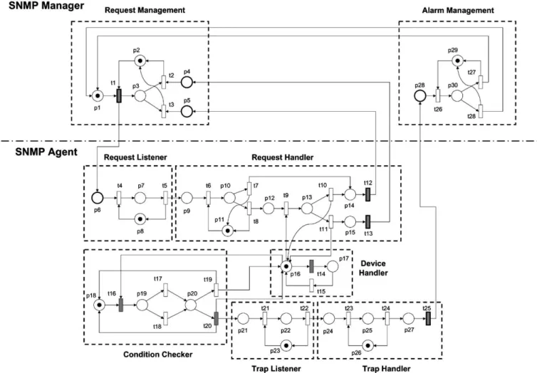
Based on the sequence diagram and class diagram con-structed using UML, information can be extracted to build a PN model. The simplified PN of the remote monitoring and control system for the mobile switching center is shown in Fig. 7. It consists of 30 places and 28 transitions. Corresponding
Fig. 7. The PNs of the SNMP-based monitoring and control system.
notations are described in Table I. For example, the dynamic behavior of the RequestHandler in Figs. 4(a) and 6 is modeled as p9-p15 and t6-t13 in Fig. 7. The software package PETRI
Maker is adopted to verify the qualitative and quantitative
prop-erties of the PN model because of its graphical representation, ease of manipulation, and its ability to perform structural and performance analyses [20].
B. PN Analysis
In our qualitative analysis, validation results via the PN mod-eling show the present design to be live and bounded. The live-ness property means that the system can be executed properly without deadlocks, while the boundedness property means that the system can be executed with limited facilities (e.g., limited request buffer size). For quantitative analysis, appropriate pa-rameters such as the time period and the probability of an alarm occurring are assigned for the timed PN modeling. Simulation results show that t1, t12, t13, and t25, drawn with dark sym-bols in Fig. 7, are critical timed transitions of the system. These critical time delays are dependent on the transmission rate be-tween the manager and agent. For example, if the data rate on the line is 512 K bps, i.e., 64 K characters per second, then the delay is 1/64 K second per character. Since the SNMP rides over UDP/IP, of which the maximum packet size is 64 K, the delay will be 1 s if there is no significant network congestion. On the other hand, the delay time of t20 can be chosen to avoid sending
a great number of traps to managers in a short time interval for the same alarm condition. In our case, we choose a delay of 30 s for t20. That means that if an alarm is reported to the manager, but the agent does not receive an acknowledgment within 30 s from the manager (i.e., TestRequest or TrapAck), the designed agent will send the trap again for this alarm condition.
In addition to finding the critical timed transitions, the PN model can also be used to decide time periods, such as t14 (time period in which to scan the real I/O status) and t16 (time period in which to check the data in DataTable), by performing sensi-tivity analysis based on the p-invariant or static cycle methods [12], [13].
VI. ARCHITECTURALDESIGN ANDIMPLEMENTATION
A. Architectural Design With the Deployment Diagram
A deployment diagram is used to model the physical relation-ships among software and hardware components in the deployed remote monitoring and control system, as shown in Fig. 8. It includes a set of nodes (drawn as cubes) to represent the com-putational units and relationships among three main machines: 1) the management station; 2) management agent; and 3) man-aged devices. The management station uses the SNMP Manager to communicate with the SNMP Agent through an Ethernet con-nection, while the management agent uses the Device Handler to communicate with the managed devices such as sensors and
Fig. 8. Architectural design with the deployment diagram.
actuators through PLC I/O connections or the industrial network Modbus.
B. Implementation With Java Technology
The system modeling and analysis developed in previous stages provide standard models for implementation of the present remote monitoring and control technology. Although UML modeling is not restricted to any particular language in implementation, Java is preferred due to its object-orientation, portability, safety, and built-in support for networking and concurrency. Moreover, Java also possesses several features for real-time development [21]–[23]. In the implementation of the present design, we need to translate information from multiple UML and PN models into the code and database structure. This translation is not straightforward. However, there is a close correspondence between Java and UML, and a standard mapping is described in [24]. Also, a mapping between PN and Java is described in [25] and a realistic implementation of PN by using Java is shown in [16]. Moreover, since Java cannot directly control the I/O devices, the ladder diagram implemented on the PLC is applied to make the SNMP agent access the low-level sensors and actuators. The developed SNMP agent is implemented on the Mirle SoftPLC (80486-100 CPU), which is an advanced industrial PLC with a built-in Java virtual machine so that it can execute both the Java and ladder diagrams [17], [18]. Fig. 9 shows the hardware setup during prototype development.
The developed SNMP-based remote monitoring and control system in this paper is now operating at an MSC belonging to
Fig. 9. The hardware setup during prototype development.
Taiwan Cellular Corporation. A total of 316 sensors and 140 actuators are handled by two PLCs with 189 rungs in each ladder diagram. Under normal operation, the desirable temper-ature and humidity of the MSC are locally controlled by air conditioners and only remote monitoring is needed. As any faults occur in the MSC, the SNMP agents will immediately send alarm signals to the three remote management stations, and proper control actions will then be taken to correct the faults. Thus, environmental conditions in the MSC are super-vised by the local SNMP agents and can be further monitored and controlled by the remote manager from great distances through the Internet.
VII. DISCUSSION
This paper integrates the PN into UML modeling to achieve design, modeling, analysis, verification, and implementation of remote monitoring and control systems within a systematic framework. The results of this study lead to the following discussion.
1) The models developed here for application to SNMP-based remote monitoring and control of mobile switching centers are general models. Since the UML is based on the object-oriented concept, reusable models can be grouped into a library to make the design process more efficient when similar SNMP applications are encountered. 2) Basically, if SNMP traps are allowed to go
unacknowl-edged, SNMP agents cannot guarantee that a critical mes-sage definitely reaches the management station. In this paper, TestRequest and TrapAck are further proposed to respond to the traps and, thus, the present SNMP agents ensure that conditions requiring attention in the moni-tored systems or processes are not missed.
3) Security is a prime concern for many network control systems. Since the basic SNMP provides only trivial au-thentication, security is particularly an important issue in the present remote system design. Therefore, user/pass-word and IP-access policies were adopted to control the user access in the present approach. In fact, basic SNMP is better suited for remote monitoring than for remote control. However, several solutions have been proposed to improve the access-control policy of SNMP, such as Secure-SNMP (S-SNMP) and SNMPv3 [26]. Therefore, improving the security of the remote system in the future by applying the new SNMP policies should be feasible.
4) The development of computer software for automatic model transformation, with due consideration given to model consistency and semantics, has attracted much attention in recent research [8]. For example, [9] and [10] have recently reported separately on work to achieve a transformation from Sequence Diagram and Statechart to PN. Instead of developing an automatic model transfor-mation, the present paper provides a systematic design approach that combines UML modeling, PN analysis, and Java realization to achieve a large-scale remote monitoring and control system. The design guidelines and analysis developed in this paper will be beneficial to future research into automatic model transformation.
VIII. CONCLUSION
This paper presents an object-oriented approach to achieve the systematical design and implementation of SNMP agents for remote monitoring and control systems. In the UML-based de-sign of the SNMP agents, the use-case diagram and the sequence diagram are applied to describe the functionalities and interac-tions, respectively. Then, a class diagram is used to describe static structures, and the PN model is further applied to verify the dynamic behavior of the system. In addition, the deployment diagram is used to model the distribution of physical compo-nents in the system. Implementation is then accomplished using the Java language and ladder diagrams on the PLC. For the man-agement of large-scale and distributed systems, the proposed multiparadigm approach provides systematic design and imple-mentation of SNMP agents to achieve remote monitoring and control by integrating UML modeling and PN analysis.
ACKNOWLEDGMENT
The authors would like to thank Dr. F. Tsai, Engineering Director of the Industrial Control Business, Mirle Automation Corporation, Hsinchu Science-Based Industrial Park, Taiwan, for his great help in developing this work.
REFERENCES
[1] A. Weaver, J. Luo, and X. Zhang, “Monitoring and control using the Internet and Java,” in Proc. IEEE Int. Conf. Industrial Electronics, San Jose, CA, 1999, pp. 1152–1158.
[2] R. L. Kress, W. R. Hamel, P. Murray, and K. Bills, “Control strategies for teleoperated Internet assembly,” IEEE/ASME Trans. Mechatron., vol. 6, no. 4, pp. 410–416, 2001. Focused section on Internet-based manufac-turing systems.
[3] G. Q. Huang and K. L. Mak, “Web-integrated manufacturing: Recent developments and emerging issues,” Int. J. Comput. Integrated Manuf., vol. 14, no. 1, pp. 3–13, 2001. Special Issue—Web-Integrated Manu-fact..
[4] C. Batur, Q. Ma, K. Larson, and N. Kettenbauer, “Remote tuning of a PID position controller via Internet,” in Proc. American Control Conf., Chicago, IL, 2000, pp. 4403–4406.
[5] M. Kunes and T. Sauter, “Fieldbus-Internet connectivity: The SNMP ap-proach,” IEEE Trans. Ind. Electron., vol. 48, pp. 1248–1256, Oct. 2001. [6] W. Stallings, SNMP, SNMP2, and CMIP. Reading, MA:
Addison-Wesley, 1993.
[7] G. Booch, J. Rumbaugh, and I. Jacobson, The Unified Modeling
Lan-guage User Guide. Reading, MA: Addison-Wesley, 1999.
[8] P. J. Mosterman and H. Vangheluwe, “Computer automated multi-paradigm modeling in control system design,” in Proc. IEEE Int. Symp.
Computer-Aided Control Systems Design, Anchorage, AK, 2000, pp.
[15] R. Zurawski and M. C. Zhou, “Petri nets and industrial applications: A tutorial,” IEEE Trans. Ind. Electron., vol. 41, no. 6, pp. 567–583, 1994. Special Section—Petri Nets Manufact..
[16] J. S. Lee and P. L. Hsu, “Remote supervisory control of the human-in-the-loop system by using Petri nets and Java,” IEEE Trans.
Ind. Electron., vol. 50, pp. 431–439, June 2003.
[17] SoftPLC Controller User’s Manual Version 1.2, Mirle Automation Corp., Hsinchu, Taiwan, 1999.
[18] SoftPLC-Java Programmer’s Toolkit, SoftPLC Corp., Spicewood, TX, 1999.
[19] J. Vucetic and P. Kline, “Signal monitoring system for wireless network operation and management,” in Proc. SBT/IEEE Int. Symp.
Telecommu-nications, Sao Paulo, Brazil, 1998, pp. 296–300.
[20] A. Godon and F. Bousseau, High-Level Timed PN Simulator, PETRI
Maker 3.1. Angers, France: ISTIA, Univ. Angers, 1996.
[21] E. Bertolissi and C. Preece, “Java in real-time applications,” IEEE Trans.
Nucl. Sci., vol. 45, pp. 1965–1972, Aug. 1998.
[22] K. Nilsen, “Real-time programming with Java technologies,” in Proc.
IEEE Int. Symp. Object-Oriented Real-Time Distributed Computing,
Magdeburg, Germany, 2001, pp. 5–12.
[23] R. F. Mello and C. E. Moron, “A Java real-time kernel,” in Proc. IEEE
Int. Conf. Industrial Electronics, San Jose, CA, 1999, pp. 728–734.
[24] Unified Modeling Language/Enterprise JavaBeans (UML/EJB)
Map-ping Specification, May 2001.
From July 2003 to June 2004, he has been a Vis-iting Doctoral Student and assigned as a Research As-sociate in the Department of Electrical and Computer Engineering, New Jersey Institute of Technology, Newark, NJ. His current research interests include In-ternet-based monitoring and control, discrete event systems, supervisory con-trol, hybrid systems, factory automation, and intelligent transportation systems.
Pau-Lo Hsu (M’92) received the B.S. degree from
National Cheng Kung University, Tainan, Taiwan, R.O.C., in 1978, the M.S. degree from the University of Delaware, Newark, in 1984, and the Ph.D. degree from the University of Wisconsin, Madison, in 1987, all in mechanical engineering.
Following two years of military service in King-Men, he was with San-Yang (Honda) Industry during 1980;V1981 and Sandvik (Taiwan) from 1981 to 1982. In 1988, he joined the Department of Electrical and Control Engineering, National Chiao-Tung University, Hsinchu, Taiwan, R.O.C., as an Associate Professor. He became a Professor in 1995. From 1998 to 2000, he served as the Chairman of the Department of Electrical and Control Engineering. His research interests include mechatronics, CNC motion control, servo systems, network-based control systems, and diagnostic systems.

![Fig. 2. The simple network management protocol (an extension of [6]).](https://thumb-ap.123doks.com/thumbv2/9libinfo/7570980.125204/3.918.202.684.92.444/fig-simple-network-management-protocol-extension.webp)