行政院國家科學委員會專題研究計畫 成果報告
新穎材料開發關鍵核心設施計畫--雷射分子束氧化物磊晶
平台之延伸
研究成果報告(精簡版)
計 畫 類 別 : 個別型 計 畫 編 號 : NSC 98-2119-M-009-016- 執 行 期 間 : 98 年 06 月 01 日至 99 年 08 月 31 日 執 行 單 位 : 國立交通大學材料科學與工程學系(所) 計 畫 主 持 人 : 朱英豪 共 同 主 持 人 : 莊振益、張立 報 告 附 件 : 出席國際會議研究心得報告及發表論文 處 理 方 式 : 本計畫可公開查詢中 華 民 國 99 年 11 月 24 日
中文 中文 中文 中文摘要摘要摘要摘要 氧化物材料具有多樣之結構特性,可以形成簡單之二元氧化物,亦可形成複雜之多元 氧化物,同時包含許多特殊之優良性質,舉凡超導特性、巨磁阻特性、焦電、壓電、介電、 半導、導電、磁性、光性等,幾乎包含所有物理性質。氧化物電子目前正蓬勃之發展,為 下一個世代之電子元件提供另一種解決方案。 本計劃第一年已獲補助建立雷射分子束磊晶,可以快速大幅提升我國學界與業界在氧 化物磊晶研發之實力。計劃要建立之系統雷射分子束磊晶平台,將具有高工作氣壓之 RHEED 來進行臨場薄膜之成長,這樣的系統可以提供氧化物磊晶薄膜技術龐大之資料庫。 此一磊晶成長平台之建立,可以快速提昇我國於氧化物磊晶成長之基礎能力,可以繼續利 用此平台研發新穎與新功能之材料。高品質之材料為固態物理研究之基石,此平台建立後, 已經為以量測為主之研究群,提供樣品確保其樣品之品質。另外對於成長氧化物磊晶有興 趣之研究群,這樣的平台提供共同研發之機會,可以藉由計畫主持人長期之經驗,快速的 建立起新製程,以利其他研究群材料之快速開發。 第二年將計畫延伸此平台之完整性與功能性,在此系統上增加高真空掃描系統,此系 統除了可以解決目前成長系統研發速度受限之缺點,亦可提供另一個快速與安全平台,可 以讓成長我之高品質磊晶薄膜立即進行特性之量測,此兩部分相輔相成,可以將我國氧化 物磊晶之技術更往前邁進一步,利用第二年之計畫補助,本研究團隊已成功將高真空掃描 系統與雷射分子束磊晶系統成功整合,建立最快速的檢測平台,部份研究成果已將寫為論 文等待發表。配合雷射分子磊晶之研究也準備以許多論文形式發表。 此系統已成為國內成長氧化物薄膜之模範平台,進而厚植本國在此領域研發之能力。 此一平台亦提供業界快速取得多功能與高品質之氧化物磊晶,有助於縮短業界開發新製程 與元件之研發時間,同時間由於各種氧化物搭配亦由此一平台提供,亦提供業界元件製程 與整合所遇到困難之解決方案。 關鍵字: 雷射分子束磊晶、氧化物薄膜、綠能壓電材料、鐵電材料、多鐵壁域、鐵酸鉍 Abstract
Oxide materials are gifted systems, providing a variety of physical properties, including superconducting, ferroelectric, piezoelectric, magnetic, CMR, optical, conducting and et al. The combinations of these properties provide new solutions of next-generation electron devices. The goal of this project is to build up a laser molecule beam epitaxy (MBE) system to fabricate epitaxial oxide heterostructures. Because it has the advantages of high quality epitaxial growth, fast optimization, and good composition and interface control, it has been a core technology on developing oxide heterostructures for many years. Such a platform will greatly promote the ability of studying oxide electronics in academia and industry. Such a system will help us to build up a database for oxide epitaxial growth and to understand the fundamental physics in behind. Such a platform can be used to develop new functional oxide materials and heterostructures. It can also be used to provide high-quality epitaxial oxide films for research groups to do other detail measurements. It can also be used as a platform for industry to develop new oxide devices. It will be an efficient approach to integrate research energy in academia and industry.
First year, we have built up the Laser-MBE system, and it shows the capability to control the film growth. Second year we have built up a high vacuum scanning probe microscope which will provide us an environment to in-situ characterize the quality of the substrates, and to understand the properties of our new functional oxide epitaxial films. The combination of laser MBE and SPM is a powerful and fast tool to develop the basic understanding of oxide films, which will be useful and helpful to academic research and industry.
Keywords: laser MBE, epitaxial, superlattice, termination control
前言 前言前言 前言 本計劃主要目標為延續去年已建立雷射分子束氧化物磊晶平台 統,目前此平台持續提供高品質之氧化物磊晶薄膜於國內外超過 Materials期刊發表兩篇論文,成果豐碩, 物磊晶薄膜之開發,並提供新的功能性與快速檢測之平台 與主系統有較好之匹配),建置於主系統上 另外為了加速平台檢測樣品之能力,計畫添購高真空掃描式探針系統 所示,並開始使用,提供平台使用者快速檢測之功能 圖 圖 圖 圖 1 雷射分子束氧化物磊晶實驗室平面圖雷射分子束氧化物磊晶實驗室平面圖雷射分子束氧化物磊晶實驗室平面圖雷射分子束氧化物磊晶實驗室平面圖 圖 圖圖 圖 2 本計劃主要目標為延續去年已建立雷射分子束氧化物磊晶平台,圖 1 為平台實驗室之平面圖 目前此平台持續提供高品質之氧化物磊晶薄膜於國內外超過 20 個研究團體使用,第一年重要成果包含於 ,平台功能已達世界級之水準。為了擴展其功能性 並提供新的功能性與快速檢測之平台。第二年在設備上規劃添購單原子氧與氮槍 建置於主系統上,如圖 3 所示,已增加系統之功能性,目前已架設完成 計畫添購高真空掃描式探針系統(Veeco Escope), 提供平台使用者快速檢測之功能。 雷射分子束氧化物磊晶實驗室平面圖 雷射分子束氧化物磊晶實驗室平面圖 雷射分子束氧化物磊晶實驗室平面圖 雷射分子束氧化物磊晶實驗室平面圖 2 雷射分子束氧化物磊晶主系統實圖雷射分子束氧化物磊晶主系統實圖 雷射分子束氧化物磊晶主系統實圖雷射分子束氧化物磊晶主系統實圖 為平台實驗室之平面圖,圖 2 為平台主系 第一年重要成果包含於 Nature 為了擴展其功能性,以利平台之對於新氧化 第二年在設備上規劃添購單原子氧與氮槍(Pascal:為了 目前已架設完成,並以開始使用。 ,目前亦已完成建構,如圖 4
圖 圖 圖 圖 3 單原子氧或氮槍與主系統建構實圖單原子氧或氮槍與主系統建構實圖單原子氧或氮槍與主系統建構實圖單原子氧或氮槍與主系統建構實圖 圖圖圖 4 系統檢測掃描探針系統建構實圖圖 系統檢測掃描探針系統建構實圖系統檢測掃描探針系統建構實圖 系統檢測掃描探針系統建構實圖 第一年之成果主要於 2009 年 1 月在國際知名期刊 Nature Materials 發表[1],第一個團隊發現多鐵材 料之壁域可以導電,提供了奈米材料與研究設計之新思維。接著於 2009 年 6 月又於同本期刊發表新的憶 阻器材料[2]。第二年之研究成果,持續以第一年所開發之新穎材料與國內外研究團隊合作,持需探索新 的科學。2009 年 11 月於國際知名期刊 Science 刊登新穎無鉛綠能壓電材料,提供了科學與工程對於高效 能之壓電材料一種新的思維與選擇[3]。2009 年 12 月於國際知名期刊 Nature Nano.發表利用電場控制之鐵 電渦流體,不論對於鐵電領域或是多鐵材料領域,多屬創新之作,受到國際矚目[4]。此外,本研究平台 合作之研究團隊,發現在於多鐵壁域有一內建電場,利用此電場可以展示新的奈米光伏可控元件,已被 Nature Nano.於 2010 年 3 月發表,重要結果如圖 5 所示[5]。 由於計畫主持人在此領域成果卓越,因此被 邀請於國際上最好的材料科學期刊,邀請寫 review 文章[6]。除此之外,此平台每年可發表超過 15 篇論 文於國際高水準之期刊,已達原本設定之目標[7-22]。 圖 圖圖 圖 5 雷射分子束氧化物磊晶平台之主要研究果雷射分子束氧化物磊晶平台之主要研究果雷射分子束氧化物磊晶平台之主要研究果雷射分子束氧化物磊晶平台之主要研究果 製程開發 製程開發製程開發 製程開發 為 了 得 到 具 有 良 好 磊 晶 性 質 的 薄 膜 , 基 板 的 選 用 有 以 下 之 考 量 : 1. 以 單 成 份 階 層 (Single-Termination)、單晶且乾淨之材料作為磊晶薄膜之基板。2.基板需要擁有原子階層級平坦 之表面,利用其調控薄膜二維成長的模式。3.利用已知表面成份原子之單成份階層以控制薄膜結 構 4.選用與磊晶薄膜晶格常數相近的之材料作為基板,可避免磊晶的薄膜與基板介面晶格常數 差異所造成的影響。 由此可見,基板處理能力之建立為成長高品質薄膜之關鍵步驟,常用以作為複雜性氧化物
磊晶的基板有 YAlO3(YAO)、SrTiO3(STO)、LaAlO3(LAO)、NdGaO3(NGO)、NdScO3(NSO)與
資料庫。 圖 6 為氧化物單晶基板處理之流程圖。製作完成之氧化物單晶晶棒切割完後,因有不 完美切割(Miscut)存在,為此,未處理的基板表面為混合之原子台階層,為了得到具有良好磊晶 性質的薄膜,控制基板為特殊成份之單一原子台階層是相當重要的。 圖 6 氧化物單晶基板處理之流程圖 利用適當的化學蝕刻步驟搭配高溫退火,可以對基板表面作有效的表面階層控制。圖 7 於 本實驗室中,將不同晶格常數基板經過化學蝕刻後,在高溫退火完之表面影像圖,可以看見原 子台階,證明此研究團隊已有基板處理能力,可以控制基板表面之 termination。 圖 7 不同晶格常數基板經過化學蝕刻後在高溫退火完之表面影像圖 利用已建立之基板處理能力,開始利用已建好之系統,進行氧化物薄膜與奈米結構之開 發。初期之開發以單相氧化物薄膜與奈米結構。計畫主持人利用本身之經驗,已陸續完成幾種 關鍵材料之製程優化,如:SrRuO3, LaNiO3, YBCO, La0.7Ca0.3MnO3, La0.7Sr0.3MnO3, La05Sr0.5CoO3,
BiFeO3, BaTiO3, PbZr0.2Ti0.8O3, SrTiO3, LaAlO3與相關材料之特殊奈米結構,並以開始提供平台初
期參與之研究群高品質之薄膜,以利研究群進行下一步之研究。除此之外,本平台亦開發出一 些新型之氧化物材料結構,將簡述如下,相關成果已開始撰寫論文,準備發表。
在單相材料之開發上,計畫總主持人在 BiFeO3薄膜之成長為國際權威,因此在此關鍵材
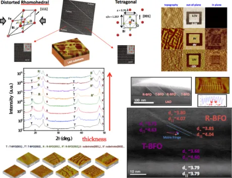
料之開發上持續進展,以供研究群團隊之使用。目前本實驗室率先開發出利用磊晶應變誘發同 對稱性之相變化(Iso-Symmetric Phase Transition),如圖 8 所示,在極大之壓應力下可以創造出接 近於 tetergonal 相,其鐵電方向可以接近於 001 方向,在張應力之狀態下,可以開發出其鐵電方 向為平行膜面,結果如圖 9 所示。目前該成果在整理階段,準備發表論文[23]。
圖 8 利用基板應變誘發 BiFeO3同對稱性相變化 圖 9 調控不同相之 BiFeO3薄膜其鐵電方向 除此之外,本實驗室另外聚焦於 BiFeO3薄膜於 LaAlO3基板之成長,目前發現可以利用 薄膜厚度來控制相的穩定,在很薄的時候為 tetragonal 相,在厚度很厚時則因為應變鬆弛而回到 菱形母相,在中間的厚度,則會形成兩相共存,部分結果如圖 10 所示,本實驗室所提供之薄膜 品質目前領先世界,實驗成果已整理成論文,即將投稿[24],這樣的系統以提供給世界數個研究 群進行實驗,目前發現具有超高的壓電特性與特殊的磁性,將於國際合作部分展現成果。為了 將其更進一步推進至實際應用,我們與美國 Cornell University 之 Prof. D. G. Schlom 合作,由其
提供利用分子束磊晶成長 LAO/Si 基板,本實驗室則將在 LaAlO3之成果成功複製於此基板上, 並且讓兩項共存更多更密,將有助於特形之提昇,目前此部份之成果已經開始整理,如圖 11 所 示,即將投稿於國際期刊[25]。同樣的概念可用於張應變之 BiFeO3薄膜,利用 NdScO3基板可長 出 orthorhombic 相,隨著厚度之增加,也會開始有菱形晶母相,而形成這兩相共存的狀態,如 圖 12 所示,目前數據整理中,準備投稿[26],同時間正尋找適當之底電極,以利下一步之電性 量測。
圖 10 在 LaAlO3基板上利用厚度控制 tetragonal 相與菱形晶相共存之部分實驗成果
圖 11 在 LaAlO3/Si 基板上利用厚度控制 tetragonal 相與菱形晶相共存之部分實驗成果
同時間為了更進一步的控制 tetragonal 相與菱形晶相的混合之型態,本實驗室也率先國際 開始選用離子,如: La3+ , Pr3+來部分取代 BiFeO3薄膜內的 Bi3+離子,用以調整菱形母相之結構, 可以改變 tetragonal 相與菱形晶混合的形狀,可由片狀結構,轉變成柱狀結構,目前實驗屬於起 始階段,部分研究成果可如圖 13 所示。 圖 13 在 LaAlO3基板上利用離子取代控制 tetragonal 相與菱形晶相共存之部分實驗成果 除了 BiFeO3薄膜之外,本實驗室亦積極開發新的材料,目前有成果的為 BiMnO3薄膜, 我們同樣利用磊晶應變,將 BiMnO3薄膜成長於 LaAlO3基板創造出新的相,如圖 14 所示,目前 仍在努力理解此新相為何,而且此新相具有自發序化結構,序化結構為兩個晶格,目前傾向於 認為是 Mn 離子的價數不同與形成的序化結構。目前積極利用 TEM 與同步輻射 X 光吸收光譜來 了解此新相的結構與特性。 圖 14 新具有序化的 BiMnO3相成長於 LaAlO3基板部分實驗數據 在氧化物特殊奈米結構之研發上,計畫主持人所帶領之研究團隊,利用不同之基板表面, 具有不同之表面能與晶格常數成長 BiFeO3-CoFe2O4,可以製作出不同形狀之奈米結構,如圖 15
所示,目前更與 Prof. Long-Qing Chen (Penn State U.)與清大材料賴志煌教授進行合作,由該團隊 進行模擬,另一團隊進行磁性量測,以了解其形成之細部過程,待此步驟完成後,將撰寫論文 發表[27]。除此之外,本實驗室亦發展其他材料之奈米結構,目前較有成果的為 Pb(Zr,Ti)O3之奈 米線,主要利用金當催化劑,來成長奈米線,如圖 16 所示,目前成果正在整理,將撰寫論文投 稿[28]。這個部分之突破在於將目前之方法延伸至多元系統之材料,目前實驗室將會以此為基準, 積極開發 ABO3材料奈米線與奈米異質結構,希望可以利用薄膜了解特性,進而利用奈米結構改 造其特性,創造出新的材料物性。
圖 15 控制不同奈米結構之 圖 16 Pb(Zr,Ti)O 上述主要在於單一材料於薄膜或奈米結構之開發 到良好的介面,必須要即時監測薄膜成長時發生的變化 裝反射式高能電子繞射裝置(RHEED) 變化與表面狀況。進而可以達到精準的厚度與原子階層控制 劃中之關鍵材料為 BiFeO3,圖 17 薄膜之成長模式調成 layer by layer 圖 17 利用 RHEED 控制不同奈米結構之 BiFeO3-CoFe2O4薄膜之部分研究成果 16 Pb(Zr,Ti)O3奈米線成長部分實驗數據 上述主要在於單一材料於薄膜或奈米結構之開發,目前多數元件多需要多層結構 必須要即時監測薄膜成長時發生的變化,本研究團隊於脈衝雷射沈積系統上加 RHEED),利用繞射的圖形與強度加以辨別薄膜成長的模式 進而可以達到精準的厚度與原子階層控制,得到磊晶性質良好的薄膜
17 為利用 RHEED 監控 BFO 薄膜之成長在 LAO layer by layer,以確保表面單一之 termination。
RHEED 監控 BFO 薄膜之成長在 LAO 基板上 薄膜之部分研究成果 目前多數元件多需要多層結構,為了得 本研究團隊於脈衝雷射沈積系統上加 利用繞射的圖形與強度加以辨別薄膜成長的模式、厚度 晶性質良好的薄膜。本計 LAO 基板上,可以將 基板上
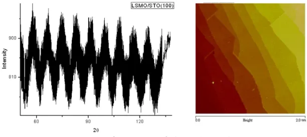
本研究團隊在系統設置之初,積極成長了許多高品質的氧化物薄膜與研發新製程,為了再 現 BFO 與 LSMO 之巨觀耦合之證據,本實驗室亦在處理後之 STO 基板上成長了高品質之 LSMO 薄膜,圖 18 為成長時即時之 RHEED 震盪圖形與成長後試片表面之原子力顯微鏡掃描圖。透過 RHEED 震盪圖形,我們得以確定成長之速度與模式,進而精準調控磊晶之製程。
圖 18 LSMO 成長即時之 RHEED 震盪圖形與成長後試片 AFM 圖
本研究團隊目前已建立單一薄膜之介面控能力,兩種鈣鈦礦結構材料在接合時有兩種不同 之接法,本研究團隊在對此控制上,亦有成果。在薄膜介面之控制亦有所成果,已成功控制 LSMO 與 BFO 兩種材料之介面,藉由 TEM 之觀察發現兩介面之晶格間距有極大之差異,如圖 19 所示, 預期會對介面磁性與電性有很大之影響,相關成果與量測持續進行中。 圖 19 控制 LSMO 與 BFO 兩種材料之接面 最後實驗所要製作之結構為超晶格,目前持續努力製作 BFO/LSMO 之超晶格,尚未有實際 之數據。然而研究團隊成員對於 YBCO/LCMO 之介面有濃厚之興趣進行研究。所以本研究團隊 亦開發具有 unit cell 控制能力之 YBCO/LCMO 超晶格結構,如圖 20 所示,利用 RHEED 分別監 測 LCMO 與 YBCO 之成長模式與速率,可以確定 layer by layer 之成長模式,進而將兩材料製作 為超晶格結構,如圖 42 所示。可以看到 YBCO 材料即使到了第 20 個週期結構,都還可以看到 RHEED 強度之震盪,這種控制的開發展現了本研究團隊具有能力開發出領先國際水準之氧化物 磊晶薄膜。進一步之 XRD 與 X-ray 反射率之量測都可以證明超晶格結構之準確與平整之介面。 軟 X 光共振散射實驗已開始進行,數據整理中。
圖 21 磊晶控制 YBCO 與 LCMO 之超晶格結構 研究合作 研究合作研究合作 研究合作 新穎核心設施之計畫概念,在於建立可以提供高品質之材料,以厚植本國在該領域之 研發實力。在培養實力之過程,與國外學者之研究合作至為重要。計畫總主持人回國時間不長, 但是在國外就與數十個知名之研究團體進行合作,因此在推廣平台之過程,一開始之主要對象 亦與國外為主。計畫推廣後到目前為止主要的以發表成果,可以在之前的部份找到,目前仍有 需多在進行的題目,以下將大概描述,以確定平台與國際合作之活力。計畫主持人於寒暑假都
前往 UC Berkeley Ramesh’s group 進行技術交流。由於計畫主持人具有成長 BiFeO3磊晶薄膜之
關鍵技術,因此在寒暑假都指導 UC Berkeley 之研究群成長該薄膜,同時也利用台灣現有之系統, 提供薄膜與該研究團體。 計畫主持人與美國 Prof. L. W. Martin 合作多年,目前美國伊利諾大學 香檳校區將投入資源建立氧化物磊晶平台,並聘任 Prof. Martin 為計畫領導人,所已計畫主持人 持續與 Prof. Martin 合作。為了要確保平台於氧化物介面之研究方向,可以在最短之時間展現成
果,本平台亦與荷蘭 Twente 大學的 Dr. M. Huijben 合作,並進行 LSMO/BiFeO3之介面控制。在
掃描探針技術之合作團隊亦沒有因為主持人回台灣而中斷掉,主持人利用磊晶平台,再度提供
高品質之 BiFeO3薄膜於美國 Oak Ridge 國家實驗室之 Prof. Kalinin,該研究團隊研究鐵電材料的
尺寸效應與電極材料間之耦合作用。另一個掃描探針之合作對象為美國康乃狄克大學之 Prof.
Huey,主要是由平台提供高品質 PZT 與 BiFeO3鐵電薄膜,由該研究群進行超高速壓電力顯微鏡
之研究 。在 TEM 的部份,本平台與美國 Oak Ridge 國家實驗室 Prof. Pennycook 有密切合作,
目前利用掃描式穿透電子顯微技術(STEM)研究 BiFeO3與 LSMO 的介面,可以發現在 BiFeO3氧
的八面體在接近介面時其旋轉消失會造成 BiFeO3變成導電之特性。另外一個重要的合作對象為
澳洲新南斯威爾大學之 Prof. Vanaloor,雙方平台之交流相當廣泛,薄膜成長、TEM 觀察、掃描 探針技術、奈米結構成長。在電性量測上,目前國外主要之合作對象為首爾國立大學的 Prof. Kim, 雙方合作的題目相當廣泛,基本上只要是本平台開發出來之新式薄膜,該研究團隊都有興趣進 行量測。理論的計算主要與美國加州大學 Santa Barbara 分校之 Prof. Spaldin,還有新加坡南洋理 工大學之 Prof. Lang Chen。除了以上之外,仍有多個國外研究群與本計劃平台合作,目前正進 行實驗中,尚未有具體成果,另有數個研究群向計畫總主持人請求信件證明,以保證此平台將 會提供其高品質之磊晶薄膜,以利該研究群計畫之申請,因此證明目前之磊晶平台已具有國際 之水準,可以提供國外研究團隊高品質磊晶薄膜,以厚植本國在氧化物磊晶薄膜之研發能力。 本計劃平台在成長關鍵新穎薄膜時需要靶材,但是一些新穎材料並無商用靶材,因此必 須與國內製作陶瓷材料之研究團隊合作開發靶材,目前主要的合作對象為海洋大學之張宏宜教 授,由其實驗室提供特殊靶材。本平台之重點希望可以培養出國內之研發團隊,所以國內合作 之研究亦為重要指標。國內之研究起步比較晚,主要是因為計畫主持人剛回國不久。最早之合 作對象為清華大學吳泰伯教授,另一個主要合作對象為成大物理系陳宜君教授,該研究團體主
要專注於掃描探針系統,因此由本計畫之主系統,提供高品質之 BiFeO3材料,利用壓電力顯微
鏡對 BiFeO3材料進行奈米尺度鐵電行為的了解。本研究平台亦與中山大學物理系邱雅萍教授合
作利用 STM 研究 BiFeO3薄膜內之鐵電域壁,可以得知域壁之能隙較小,因此造成域壁之導電
性較高,亦為此領域突破之研究。目前能源議題發燒,鐵電光伏元件為太陽能發電提供一個新 的選擇,為了了解鐵電材料與電極材料介面的能帶之變化,本平台與成大物理吳宗霖教授合作, 由本研究平台提供樣品,利用 photoemission electron spectroscopy 來了解改變鐵電極化方向對於
介面能帶之影響。與師大物理系劉祥麟教授合作研究 iso-symmetric 相的 BiFeO3之光學性質,同 系列之樣品亦跟同步輻射林宏基博士合作,由其進行軟 X 光吸收之量測。交通大學電物系由小 林孝嘉教授與吳光雄教授帶領目前正在建立飛秒雷射系統以進行相關材料超快動力學之研究, 本研究平台亦與其結合,提供高品質樣品於吳教授與羅志偉教授所帶領之研究團隊,進行多樣 化 BiFeO3薄膜超快動力學之研究。本研究平台除了積極建立基礎研究平台之外,亦希望可以將 所開發之材料推往應用之範圍,因此亦花很多時間在建立跟電機電子元件相關研究團隊之研究。 本研究平台與清大電子邱博文教授合作,結合其在傳輸量測上之專長,共同研究 BiFeO3薄膜內, 鐵電域壁之磁阻行為,目前看到約 60%之變化,亦為此領域研究上之突破。上述幾個研究群皆 是已有成果產出,因此與這些研究群之合作關係,會將持續,陸續會有成果產出。另外還有許 多國內之研究群之合作屬於起始階段,待雙方磨合期結束,便開始會有實質之數據產出,以提 高平台之利用效率。 綜合以上所述,可以得知此平台無論在國外與國內都相當活躍,提供許多 研究群高品質之氧化物薄膜,除此外還結合各個領域之研究人才,發表高品質之論文於頂尖期 刊[29-56],提供我國在此領域之研究總能量。 參考資料 參考資料參考資料 參考資料
1. J. Seidel et al., Nature Mater. 8, 229 (2009). 2. C.-H. Yang et al., Nature Mater. 8, 485 (2009). 3. R. J. Zeches et al., Science 326, 977 (2009). 4. N. Balke et al., Nature Nanotechnol. 4, 868 (2009).
5. S. Y. Yang et al., Nature Nanotechnology 5, 143-147 (2010).
6. L. W. Martin, Y. H. Chu, and R. Ramesh, “Advances in the Growth and Characterization of Magnetic, Ferroelectric, and Multiferroic Oxide Thin Films”, Mater. Sci. Eng. R. accepted (2010).
7. M. Huijben et al., Phys. Rev. B 78, 094413 (2008).
8. B. J. Rodriguez et al., Appl. Phys. Lett. 93, 142901 (2008). 9. Y. C. Chen et al., Appl. Phys. Lett. 94 122908 (2009). 10. Y. H. Chu el al., Nano Lett. 9, 1726-1730 (2009).
11. M. O. Ramirez et al., Appl. Phys. Lett. 94 161905 (2009). 12. M. C. Langner et al., Phys. Rev. Lett. 102, 177601 (2009). 13. X. S. Xu et al., Phys. Rev. B 79, 134425 (2009).
14. M. O. Ramirez et al., Phys. Rev. B 79, 224106 (2009). 15. L. Pintilie et al., Appl. Phys. Lett. 94, 232902 (2009).
16. B. J. Rodriguez el al., Adv. Funct. Mater. 19, 2053-2063 (2009). 17. S. Y. Yang et al., Appl. Phys. Lett. 95, 062909 (2009).
18. C. W. Huang et al., Phys. Rev. B 80, 140101 (2009). 19. T. H. Lin et al., J. Appl. Phys. 106, 103923 (2009). 20. S. H. Baek et al., Nature Mater. 9, 309 (2010).
21. M. B. Holcomb et al., Phys. Rev. B 81, 134406 (2010). 22. D. Pantel et al., J. Appl. Phys. 107, 084111 (2010).
23. C. K. Tung et al., “Epitaxial Strain Control of Ferroelectric Direction of BiFeO3 Thin Films”, to be
submitted.
24. C. W. Liang et al., “Growth Control of Strain Driven Iso-Symmetric Phase Boundary in Multiferroic Thin Films”, to be submitted.
25. W. I. Liang et al., “Integration of Iso-symmetric Phase Boundaries in Multiferroic BiFeO3 Thin films
on Si Substrates”, to be submitted.
26. W. I. Liang et al., “Tensile Strain Driven Morphotropic Phase Boundary in Multiferroic BiFeO3 Thin
Films”, to be submitted.
27. P. Y. Tsai et al., “Orientation Control of CoFe2O4 nanostructure in BiFeO3 Thin Films”, to be
28. T. H. Liu et al., “Growth of Pb(Zr,Ti)O3 Nanowires”, to be submitted.
29. P. Yu and et al., “Interface ferromagnetism and orbital reconstruction in BiFeO3-La0.7Sr0.3MnO3
heterostructures”, Phys. Rev. Lett. 105, 027201 (2010).
30. J. Seidel et al., “Tuning Conductivity at Domain Walls in BiFeO3 Thin FIlms” Phys. Rev. Lett.
accepted.
31. Q. He et al., “Domain Wall Magnetism and Magnetotransport in Multiferroic BiFeO3”, Nature Mater.
revised.
32. Q. He et al., “Electrically controllable magnetic isosymmetric phase boundary in multiferroic BiFeO3
thin films”, Nature Communications revised.
33. Q. He et al., “Electrically Controllable Iso-Symmetric Phase Transition in Multiferroic BiFeO3 Thin
Films”, to be submitted.
34. J. X. Zhang et al., “A road to Giant Displacementin Lead-Free Multiferroic Thin Films”, Nature Nanotechnology.
35. L. W. Martin et al.,“Nanoscale Domain Control of BiFeO3 and Exchange Interactions by Thin Film
Growth Modes”, Adv. Mater. under review (2010).
36. M. Huijben et al., “Electrically controlled magnetization in an oxide multiferroic/ferromagnet heterostructure”, Nature Mater. revised (2009).
37. P. Maksymovych et al., “The Ultrathin Limit and Dead-Layer Effects in Polrization Switcing of BiFeO3”, Phys. Rev. Lett. under review.
38. N. Balke et al., “Direct observation of capacitor switching using planar electrodes”, Adv. Funct. Mater.
20, 3466 (2010).
39. R. Nath et al., “High Speed SPM for Direct Nanoscale Mapping of Nucleation and Growth”, ACS Nano submitted (2009).
40. N. A. Polomoff et al., “Correlation between nanoscale and nanosecond resolved ferroelectric domain dynamics and local mechanical compliance”, J. App. Phys. under review (2010).
41. A. Borisevich et al., “Direct observation of the novel interface-mediated mesoscopic phase transition in multiferroic BiFeO3 by STEM-EELS imaging”, Phys. Rev. Lett. 105, 087204.
42. R. K. Vasudevan et al., “Unambiguous discovery of vortex and antivortex states in BiFeO3 Thin-Film”,
Nano Lett. submitted.
43. K. Bogle et al., “Single-crystalline metal oxide nanostructures via phase separation approach” ACS Nano 4, 5139 (2010).
44. Y. S. Oh et al., “Quantitative determination of anisotropic magnetoelectric coupling in BiFeO3-CoFe2O4 nanostructures”, Appl. Phys. Lett. 97, 052902 (2010).
45. C. W. Huang et al., “Strain-driven phase transition and associated dielectric/piezoelectric anomalies for BiFeO3 thin films”, Appl. Phys. Lett. 97, 152901.
46. H. H. Liu et al., “Kinetics on strain-driven Iso-Symmetric Phase Transition in BiFeO3 Thin Films”, to
be submitted.
47. W. Y. Chang et al., “Resistive Switching Characteristics of BiFeO3 Thin Films”, to be submitted.
48. Y. C. Chen et al, “Domain structure of strain driven isosymmetric phase boundary in multiferroic BiFeO3 thin films”, to be submitted
49. Y. C. Chen et al., “Nanoscale domain switching kinetics in epitaxial BiFeO3”, to be submitted.
50. Y. C. Chen et al., “Dynamics of domain relaxation in BiFeO3: Role of surface charge effects”, to be
submitted.
51. Y. P. Chiu et al., “Local Electronic Evolution Across Multiferroic Domain Walls”, to be submitted. 52. C. L. Wu et al., “Direct Investigation of Reversible Interface Band Bending at Ferroelectric
Heterojunction”, to be submitted.
53. M. K. Lin et al., “Optical properties of iso-symmetric multiferroic BiFeO3 Thin Films”, to be
submitted.
54. C. Y. Kuo et al., “Determination of the orientation of magnetic moment and crystal field distortion of strain driven isosymmetric phase transition in multiferroic BiFeO3 thin films”, to be submitted.
55. L. Y. Chen et al., “Ultrafast dynamics of BiFeO3 thin films by dual-color femtosecond spectroscopy”,
to be submitted.
56. M. G. Chen et al., “An investigation on the leakage current and the time dependent dielectric breakdown properties of ferroelectric (BiFeO3) thin film capacitors”, to be submitted.
1
國科會補助專題研究計畫項下出席國際學術會議心得報告
日期:9 9 年1 0 月2 0 日計畫編號
NSC 98-2119-M-009-016-
計畫名稱
雷射分子束氧化物磊晶平台之延伸
出國人員
姓名
朱英豪服務機構
及職稱
國立交通大學材料系 助理教授會議時間
98年8月22日至
98年8月26日
會議地點
中國大陸 西安會議名稱
Joint meeting of 12
thInternational Meeting on Ferroelectricity and
18
thIEEE International Symposium on Application of Ferroelectrics
發表論文
題目
Invited Talk
Electrical Control of Interfacial Properties of BiFeO
3Films
一、參加會議經過
8月22號從台灣出發經由香港轉機到西安,在機場搭計程車前往會議舉行飯店,到達飯店時,已經 接近晚上十點,因此沒有任何特殊活動,整理一下行李便休息。8月23號大會安排的是註冊與教學課程, 對於想要進入此領域的年輕學者相當的有助益,但是因為要額外付費,本人並沒有參與。飯店是由大 陸軍方管理,在西安郊區所以並無法前往其他地方,用餐也只能在飯店內提供的餐廳,所以除了用餐 外,就在飯店內準備自己的演講。 8月24號正是會議開始一早便前往會場,由主席西安交通大學的姚熹教授介紹這個會的歷史,以及 目前發展的情況。接下來則是令人比較傷心的消息,在此領域的拓荒者Penn State Univ的Robert E. Newnham教授在今年四月過世的訊息,Newnham教授為美國國家科學院院士,在壓電材料領域深耕多 年,作育英才無數,因此他過世的消息在此領域引不小的震撼,有需多的不捨與難過。接下來由Newnham 教授的得意門生,一樣是來自於Penn State Univ的Susan E. Trolier-McKinstry教授進行專題的報告,主要 就是描述Newnham教授這一生的堅持、研究的信念、對學生的教育,讓人再度感受與分享這位一代大 師的一生。接下來大會安排來自北京清華大學大陸國家電鏡中心的朱靜院士來進行專題報告,主要報 告內容為利用穿透式電子顯微鏡來觀察morphotropic phase boundary(MPB)的壓電材料,對於了解MPB 壓電材料為何有很好的壓電特性,提供最直觀的證據,用來支持為奈米兩相共存的模型。由於本人的 邀請在下午,因此聽完朱靜教授的報告,我就前往飯店準備報告。當天下午來個分項會議議程的開始, 我的邀請報告在多鐵材料分項會議,主要是由北京清華大學南策文院長規劃與邀請,前往會場時先跟 南院長打招呼,謝謝他的邀請,並進一步交換資訊,雙方初步都有合作的意願,南院長更希望我有空 可以訪問北京清華大學,以做進一步的交流。會議開始後,主要聽了上海華東師範大學的段純剛教授 所進行的報告,因為段教授的專長在於材料計算,也是我目前比較欠缺的一環,因此很希望了解其研
2
究領域,希望有機會可以與其合作。段教授的報告主要是以BaTiO3/Fe這兩雙層結構為主,利用理論計
算來預測利用電控制磁性的可能性。接下來沒多久就是本人的報告,主要是以去年本人發表於Nature Materials的論文為主Electrcially controllable ferromagnetism at room temperature,這篇論文為此領域之重 要突破,首次展現在室溫下可以利用電場來改變磁性,與會者相當多。等本來講完後,問題相當踴躍, 有引起廣泛的討論,下台後問題不斷,很多與會者都說我的演講相當好。接下來由此領域重量級學者 Prof. W. Kleeman進行演講,主要專注於他多年來於Cr2O3的發現與突破。接下來為休息時間,遇到了來 自密西根大學的潘曉晴教授,本人在國外時跟其所領導的研究團隊有廣泛之合作,因此上前打了個招 呼。然後又遇到來自南京大學物理系的朱勁松教授,這次第二次與其碰面了,上次在新加坡開會時見 過面,他也是清華大學吳泰伯教授之舊識,因此希望我可以幫忙像吳教授問好,雙方也就目前的研究 成果交換意見,並達成短期互訪的意願。接下來我前往任曉兵教授的專題演講,主要著重於超高特性 的無鉛壓電材料,相當的廣泛,不愧是這個領域目前的領先者。在晚餐前由澳洲新南斯威爾的Prof.
Nagarajan Vanaloor進行報告,主要利用穿透式電子顯微鏡來了解BiFeO3材料於doping後所造成壓電特性
提昇之微觀原由。Prof. Vanaloor為本人多年好友,也是本來合作對象之一,目前雙方也在共同撰寫論 文中,因此我跟其約好明天白天找個時間碰面,可以就雙方合作的題目進行討論。晚餐則是在飯店內 用餐,遇見同樣是來自於台灣交通大學的電子系曾俊元教授,曾教授在陶瓷領域是相當資深的研究學 者,因此就跟曾教授討論並交換意見。晚餐後遇見來自於美國Oak Ridge國家實驗室的S. V. Kalinin教授, 他是我多年來研究的合作對象,也是我此次參加會議必須要見的人之一,因為雙方有很多題目正在進 行合作,也有些論文在撰寫中,希望可以利用此次開會的機會,一起坐下來討論,並解決一些雙方在 撰寫論文所遇到的問題。晚上則會飯店準備我另一個口頭報告。
8/25號早上則前往來自於劍橋大學的Prof. J. F. Scott的演講,Prof. Scott為鐵電材料大師,目前亦專
注於多鐵材料的開發,在此邀請演講中討論Pb(Fe,W)O3材料的室溫多鐵特性,位這個領域立下新一個 里程碑。接下來由我進行報告,講題為如何利用磊晶成長技術來控制關鍵多鐵材料BiFeO3的domain structure,與會者相當踴躍,也提出相當多的問題。休息時間遇到來自南京大學材料系的吳迪教授,吳 教授跟我一樣為此領域的新進學者,因此更希望有更多的交流,雙方進行短暫的討論,達成短期互訪 的意願。然後就遇到Prof. Vanaloor,兩人便找在大會會場找個可以討論的地方進行討論,並完成雙方 在撰寫的論文。午餐時則遇見來自新加坡的姚魁教授,姚教授在鐵電光伏元件領域為權威,所發表的 文章數領先全球,與其進行短暫交談,以了解雙方研究領域合作之可能性。接下來前往來自德國Prof. C. L. Jia,Prof. Jia為氧化物領域的電鏡大師,其作品發表於Science與Nature系列,每每利用電鏡展現突破 性之研究,此次其專題演講著重於利用電鏡來看複雜氧化物的氧離子,還有如何利用電鏡的技術來分 析鐵電材料的電域壁,其在這領域的研究都是領先全球的。本來有些研究題目與其合作,但是目前並 沒有具體結果。另外本人還前往潘曉晴教授的演講,主要是利用電鏡技術來了解BiFeO3材料之鐵電
domain structures,結果相當突出。接下來的時間就與Prof. Kalinin討論目前雙方合作研究所遭遇的困難, 並完成雙方目前共撰寫之論文。今天大會安排的晚宴在市區,因此大家必須搭車前往,由一家中西式 餐廳接待,有來自於大陸排笛的國寶大師進行節目之演出,與會人士都相當盡興,會中並幫來自於Penn State Univ的一代大師L. E. Cross教授慶生,感謝他在此領域的貢獻。另外大會今年的貢獻獎則頒給Susan E. Trolier-McKinstry教授以感謝其在此領域的耕耘。 8/26號早上收拾行李,然後前往機場,在香港轉機回到台灣。
二、與會心得
這是在壓電元件與材料相當重要的會議,可以發現台灣在此領域的參加者並不多,如果無法與國 際進行交流,是很難知道目前國際在此領域的走向,因此深深覺得台灣學者應該多出國看看。整個領 域的發展是相當快速的,一下子沒注意,別人就追上了。這種場合也是認識人的好地方,尤其是像我 這樣的新進學者,建立人脈是相當重要的,所以花了很多時間在與其他研究學者建立關係。3
三、考察參觀活動(無是項活動者略)
無 略四、建議
這類會議對於新進人員幫忙相當大,應該多進行補助。五、攜回資料名稱及內容
論文摘要集1
國科會補助專題研究計畫項下國際合作研究計畫國外研究報告
日期:9 9 年1 0 月27日計畫編號
NSC 98-2119-M-009-016-
計畫名稱
雷射分子束氧化物磊晶平台之延伸
出國人員
姓名
朱英豪服務機構
及職稱
國立交通大學材料系 助理教授合作國家
美國合作機構
UC BerkeleyLawrence Berkeley National Laboratory
出國時間
98年7月2日至
98年8月17日
出國地點
美國加州柏克萊
一、國際合作研究過程
本報告內容主要為申請人暑假期間至 UC Berkeley 與美國勞輪斯國家實驗室進行短期研究之主要成
果。該研究內容以了解BiFeO3關鍵多鐵材料藉由strain 所引起之 iso-symmetric 相變化之研究。本研究利
用交通大學奈米中心高解析之X 光結晶繞射,了解此相變化之過程與薄膜裡面相對之相,同時利用新竹
國家同步輻射中心之軟X 光吸收光譜,了解純相之反鐵磁特性,最後在美國 UC Berkeley 利用高解析之
掃描探針系統,了解薄膜表面形貌與相變化之過程,最後利用美國勞輪斯國家實驗室先進光源中心之 photon emission electron microscopy 來進行具有空間解析度之實驗,了解此系統磁性之來源。
二、研究成果
The ability to use epitaxy as a tool to control the ground state of a material has enabled the discovery of a wide range of new phenomena in modern materials1,2. Recently, large compressive epitaxial strains were imposed on the rhombohedral phase (R-phase) multiferroic, BiFeO3 (BFO), to stabilize a tetragonal-like
phase (T-phase) with a significantly larger c/a ratio3. It was also demonstrated that partial relaxation of this epitaxial strain leads to the formation of a nanoscale mixture of the T- and R-phases, thus resembling a classical morphotropic phase boundary in modern piezoelectrics4,5. Over the past two decades, novel physical phenomena have emerged in complex oxides, at interfaces that are naturally created within the system (e.g., phase-separated manganites, relaxor ferroelectrics), or in artificially engineered heterostructures6,7,8,9,10,11. Although many of these phenomena have emerged as a consequence of chemical substitutions, strain control is emerging as an equally powerful tool to create and manipulate such phenomena2. In this study we describe a novel approach to create a new magnetic state in BFO and the ability to electrically control this emergent magnetism at room temperature. An enhanced spontaneous magnetization arises in the R-phase that is strain confined between areas in T-phases. We demonstrate that this local magnetic moment can be erased by the application of an electric field. Finally, reversal of the electric field polarity restores the mixed phase structure.
The samples were prepared using pulsed laser deposition in conjunction with high-pressure reflective high-energy electron diffraction to monitor the growth of the BFO thin films. A bottom conducting layer of LaNiO3 was inserted in order to eliminate charging effects during X-ray illumination. Partial strain
2
relaxation through control of the film thickness leads to the formation of two orthogonal arrays of nanoscale, T+R phase mixtures, as imaged by AFM shown in Figure 1(a). The individual stripe-like regions, Figure 1(b), consist of a nanoscale ensemble of T- and R-phases with a characteristic length scale of 20-40nm. The graph on the bottom of this figure shows a cross-sectional line-profile of the mixed phase area, revealing two different tilting angles (2.8° and 1.6° relative to the surface plane) of the mixed phase areas. The structural details of such a mixed phase ensemble were identified from careful X-ray 2θ-ω scans, such as that shown in Figure 1(c). The X-ray data also identifies the structural distortion of the R-phase, with out-of-plane lattice parameter of (c=4.17Å); this coupled with reciprocal space maps provides a measure of the in-plane dimensions of this highly strained R-phase to be 3.82 Å. From the four peaks arising from the R-phase, Figure 1(c), the tilt angles for these can be divided into two groups, one ~2.8 °and the other ~0.6°, which correspond to the green and red shaded area in Figure 1(a). The broadening angle for the T-phase (c=4.64Å) is estimated to be 1.6°, resulting from the tilting of the T-phase, consistent with the AFM measurement. Compared to the AFM line profile, we find that the R-phase with a tilt angle of 2.8° is on the other side of the peaks to the T-phase. Therefore, we can locate the R- and T-phases with the slopes of the topography shown in Figure 1(b) and schematically illustrated in Figure 1(d). The AFM and X-ray diffraction studies clearly establish the nanoscale, R-T mixed-phase ensemble, in which the R-phase is highly strained compared to the bulk. Since BFO in the bulk is a well-known ferroelectric and canted antiferromagnet 14,15,16, it is natural to ask: what is the magnetic state of the mixed phase BFO, especially in the highly strained R-phase?
X-ray magnetic circular dichroism (XMCD) is a powerful method to study the magnetic response of a material17,18. We have employed this technique to explore the magnetic response of BFO films with mixed phases, and compared to unconstrained R-and pure T-phase films. X-ray absorption spectra (XAS) at Fe3+
L2,3-edge using left and right circularly polarized soft X-rays, at grazing incidence (θ = 30°) were obtained as
a function of the external magnetic field in total electron yield (TEY) mode. Figure 2 shows the XMCD signal obtained from the difference between XAS in positive and negative (parallel and antiparallel to the k-vector of the incident X-ray) magnetic field (+/- 2 T) and fixed X-ray polarization. The red curve in Figure 2 is from a pure rhombohedral phase BFO sample, which gives a negligible XMCD signal (since the canted moment is only ~6-8 emu/cc)14. No canting of Fe3+ spins is allowed in the tetragonal phase BFO due to symmetry and thus, it does not exhibit any XMCD (data in green in Figure 2)19. The significantly larger XMCD spectra of mixed T+R phase BFO ensembles are shown as the black curves in Figure 2, indicating that a higher magnetic moment is present in mixed phase BFO films. The XMCD spectra in Figure 2 are measured with left circularly polarized (LCP) X-rays; they reverse polarity when using right circularly polarized (RCP) X-rays, confirming that the response is magnetic in origin. These measurements clearly reveal the existence of a spontaneous magnetic moment in the mixed phase samples. From the ~0.7% XMCD signal, and using data for other iron oxide systems (Fe3O4)20,21 as a semi-quantitative calibration, we
estimate the averaged magnetization to be of the order of 20-30 emu/cc in the top 5 nm (penetration depth for electrons in TEY mode) of the sample surface. In order to explore the microscopic origins of this enhanced magnetic moment, the XMCD signal was imaged using photoemission electron microscopy (PEEM).
Spatially resolved PEEM images were obtained using both LCP and RCP incident X-rays at a grazing incidence angle (θ = 30°). To enhance the difference in the magnetic contrast and eliminate the contribution from the topographic contrast, the ratio of the two images was taken. The image contrast is effectively a map of the local magnetization vector; regions that have their magnetic moment lying parallel to the X-ray wave vector show bright contrast, while those that are antiparallel appear in dark contrast. XMCD-PEEM images were taken with the incident X-rays at various orientations (ϕ = 0°, 90°, 180°), shown schematically in Figure 3(a). Figure 3(b) is the PEEM image obtained by LCP X-ray at ϕ = 0°, showing mainly topographic contrast. The darker areas in this image are in the valleys of the mixed phase features and brighter areas are at the peaks. The XMCD image, (Figure 3(c)), reveals the intrinsic magnetic
3
contrast that appears as bright and dark stripe-like patterns indicating that these stripes have magnetic moments lying parallel and antiparallel to the incident X-rays. When the sample is rotated by 180°, all of the stripes reverse contrast, which further confirms the magnetic origin, Figure 3(c). Moreover, after a 90° rotation of the sample about the sample normal, the stripes show weak or no contrast when the incident X-ray is perpendicular to their long axes; at the same time, the stripes show strongest contrast when the incident X-ray is parallel to their long sides (Figure 3(b)). These measurements clearly indicate that the magnetic moments in the stripe-like area are lying along the long axis of the stripes. It is also important to note that the regions in bright and dark magnetic contrast in Figure 3(b) are approximately of equal fractions. Temperature dependent PEEM studies (Supplementary Fig.S1) show that the magnetic contrast vanishes by ~175°C, while the topography remains unchanged; furthermore, the magnetic contrast re-appears upon cooling to room temperature.
To further explore the origins of the magnetic response (i.e., does it arise at the interface between the T/R phases OR is it located within the highly strained R-phase), we focus on the area indicated by a red square in Figure 3(c) and compare with both the AFM line scans and the corresponding piezo-response force microscopy (PFM) images of the same area. Figure 4(a) is the AFM topography image and the corresponding in-plane PFM image acquired simultaneously at exactly the same position is shown in Figure 4(b). The PFM image shows bright contrast of “lip-shaped” patterns surrounding the stripe-like features. By obtaining a line profile across the mixed phase features, the topography curve (black curve in Figure 4(d)) shows a significant asymmetry of slopes on phase on the two sides of the rhombohedral phase similar to what was shown in the cross sectional AFM line profile in Figure 1(b). Combining the in-plane PFM line profile (green curve in Figure 4(d)) with the topology scan helps us to conclude that the lip-shaped patterns form the T/R interface. More importantly, the area enclosed by the “lip-shaped” region is on the steeper side, which is the R-phase as shown in Figure 1(b). The corresponding magnetic information of the same area is obtained from the zoomed-in XMCD-PEEM image, Figure 4(c). By superimposing the PEEM and PFM line profiles together in Figure 4(d), it is clear that this highly distorted R-phase is the source of the enhanced magnetic moment in the XMCD image, arising from a piezomagnetic effect22,23,24.
Conventional SQUID magnetometry of a large set of mixed phase samples, (Supplementary Fig S2) yielded an average magnetic moment of ~5 emu/cc that is consistently higher than the pure T-phase samples that show moments ~1emu/cc. This moment in the mixed phase can be understood from a careful examination of the AFM and PEEM images coupled with XRD studies. The AFM images show a surface area fraction of the R phase of ~30-40%; however, careful analysis of 2θ-ω XRD scans [Fig.1(c)] yields a volume fraction of the R phase of ~10-15%, suggesting that the R-phase is tapered towards the substrate. From this volume fraction information the magnetic moment of the R-phase is estimated to be ~30-50 emu/cc, which is consistent with the data we obtained from surface-sensitive XMCD measurements. In order to further verify the existence of this magnetic moment we explored the exchange coupling of this moment to a ferromagnetic layer.
2.5 nm thick, ferromagnetic Co.90Fe.10 (CoFe)thin films were deposited onto BFO films containing a
large fraction of mixed phase regions at room temperature by DC magnetron sputtering in a UHV system of base pressure of ~5 x 10⁻⁸ Torr. The CoFefilms were capped with a 2 nm thick layer of Pt to prevent its oxidation. A uniform magnetic field of 200 Oe was applied during the CoFegrowth to set the uniaxial anisotropy direction. Then, Co-edge XMCD-PEEM imaging was employed in different orientations (Φ=0°, 45°, 90°, 180°) to investigate the ferromagnetic domain structures in CoFe layer. Figure 5(a) is taken with LCP X-rays, which clearly shows us the topography of mixed phase structure covered by CoFe that was grown in an applied magnetic field along [ 1 10] direction. Bar-shaped magnetic domains can be seen in the XMCD-PEEM images (Figure 5(b)-(e)). It is interesting to note that the bar-shaped domain patterns in these magnetic images strongly resemble the corresponding bar-shaped patterns (identified within the red box and schematically depicted in Figure 5(f)) in the topographic image in Figure 5(a). 5(b) was taken with circularly polarized X-rays incident from [100] direction, which shows horizontal bar-shaped domains in
4
dark contrast while vertical bar-shaped domains appear in neutral (gray) contrast, indicating that the magnetization of CoFe in the horizontal and vertical domains are pointing antiparallel ([0 10]) and perpendicular ([100] or [ 100]) to the incident X-rays, respectively. This magnetization direction coupled with the moment in the mixed phase features (along the long side of the mixed phase stripes but the short side of the CoFe domains), which is also schematically shown in Figure 5(f). When we rotate the sample by 45° with respect to the sample normal, the XMCD amplitude from the CoFe domains decreases by about a factor of √2, reflecting the reduced contrast in the PEEM image shown in Figure 5(c). This confirms our interpretation of the moment directions. With a 90° rotation of the sample, the change of contrast of XMCD-PEEM image (Figure 5(d)) suggests that the moments in the vertical CoFe domains lie along [100] direction. Finally, a 180° rotation of the sample gives us a fully reversed contrast image (Figure 5(e)), confirming the contrast we observed here is indeed magnetic in origin and that the moments in the CoFe layer are magnetically coupled to the moment in the R-phase of the BFO underlayer25. This robust magnetic coupling provides additional evidence on the existence of magnetic moments embedded in R-phase of the mixed phase nanostructures in BFO.
Having established the existence of a nanoscale magnetic moment in the highly distorted R-phase, we demonstrate the electric field modulation of this magnetism. By applying a +24V DC bias to a PFM tip and scanning over the red rectangular area (Figure 6(a)), the mixed phase features can be transformed into pure tetragonal phase. Then, applying a -8V DC bias to the green rectangular area, the mixed phase features return. Details of the electric field induced phase evolution and the corresponding changes in the piezoresponse are discussed in Ref. 26. LCP and XMCD-PEEM images of this area are shown in Figure 6. By mapping the magnetic moments (XMCD image), no magnetic contrast is observed in the area between the green and red boxes, consistent with the non-magnetic state of tetragonal phase. In contrast, the XMCD images show the characteristic stripe-shaped features both inside the green box and outside the red box area, indicative of a magnetic moment in them. Therefore, we conclude that magnetic moments in these stripe-shaped nanoscale mixed phase regions can be erased and rewritten at room temperature with only the application of an electric field.
In summary, we have demonstrated a novel approach to manipulate the canted moment of the R-phase of BiFeO3, by creating a nanoscale ensemble in which the R-phase is mechanically confined by
regions of the T-phase. This nanoscale mixture displays functional responses that are strikingly different from the parent phases, thus embodying the spirit of a morphotropic phase boundary in a relaxor ferroelectric or the electronically phase separated scenarios in the CMR manganites. Detailed analyses using a combination of experimental probes reveal that the enhanced magnetic moment resides within the distorted R-phase rather than at the interfaces. The strong coupling to the underlying lattice is a primary reason that this moment is not switchable with a magnetic field; in contrast, it can be controlled by electric fields that making it a novel vehicle to demonstrate magnetoelectric coupling and electric field control of magnetism in this multiferroic system. Deterministic control of the location, size and distribution of this mixed phase ensemble would be a critical enabler of approaches to use the results of this study in future magnetoelectronic applications.
5 References:
1 Schlom, D. G. et al. A thin film approach to engineering functionality into oxides. J. Am. Ceram. Soc 91, 2429
(2008).
2 Choi, K. J. et al. Enhancement of ferroelectricity in strained BaTiO
3 thin films. Science 306, 1005 (2004). 3 Béa, H. et al. Evidence for room-temperature multiferroicity in a compound with a giant axial ratio. Phys. Rev.
Lett. 102, 217603 (2009).
4 Zeches, R. J. et al. A strain-driven morphotropic phase boundary in BiFeO
3. Science 326, 977 (2009). 5 Chen, Z. et al. A strain-driven morphotropic phase boundary in BiFeO
3. Appl. Phys. Lett. 96, 252903 (2010). 6 Fu, H. and Cohen, R. E. Polarization rotation mechanism for ultrahigh electromechanical response in
single-crystal piezoelectrics. Nature 403, 281 (2000).
7 Chakhalian, J. et al. Orbital reconstruction and covalent bonding at an oxide interface. Science 318, 1114
(2007).
8 Ohtomo, A. and Hwang, H. Y., A High mobility electron gas at the LaAlO
3/SrTiO3 heterointerface. Nature 427,
423 (2003).
9 Reyren, N. et al. Superconducting interfaces between insulating oxides. Science 317, 1196 (2007). 10 Yu, P. et al. Interface ferromagnetism and orbital reconstruction in BiFeO
3-La0.7Sr0.3MnO3 heterostructures.
Phys. Rev. Lett. 105, 027201 (2010).
11 Garcia-Barriocanal, J. et al. Colossal ionic conductivity at interfaces of epitaxial ZrO
2: Y2O3/SrTiO3
heterostructures. Science 321, 676 (2008).
12 Nolting, F. et al. Direct observation of the alignment of ferromagnetic spins by antiferromagnetic spins.
Nature 405, 6788 (2000).
13 Scholl, A. et al. X-ray photoemission electron microscopy, a tool for investigation of complex magnetic
structures. Rev. Sci. Instrum. 73, 1362 (2002).
14 Ederer, C. and Spaldin, N. A. Weak ferromagnetism and magnetoelectric coupling in bismuth ferrite. Phys.
Rev. B 71, 060401 (2005).
15 Lebeugle, D. et al. Room-temperature coexistence of large electric polarization and magnetic order in BiFeO 3
single crystals. Phys. Rev. B 76, 024116 (2007).
16 Lebeugle, D. et al. Electric-field-induced spin flop in BiFeO
3 single crystals at room temperature. Phys. Rev.
Lett. 100, 227602 (2008).
17 de Groot, F. High-resolution x-ray emission and x-ray absorption spectroscopy. Chem. Rev. 101, 1779 (2001). 18 Ohldag, H. et al. Correlation between exchange bias and pinned interfacial spins. Phys. Rev. Lett. 91, 017203
(2003).
19 Hatt, A. J., Spaldin, N. A., and Ederer, C. Strain-induced isosymmetric phase transition in BiFeO
3. Phys. Rev.
Lett. 81, 054109 (2010).
20 Lu, Y. X. et al. Epitaxial growth and magnetic properties of half-metallic Fe
3O4 on GaAs(100). Phys. Rev. B
70, 2333-4 (2004).
21 Morrall, P. et al. Stoichiometry of Fe
3-δO4(111) ultrathin films on Pt(111). Phys. Rev. B 67, 214408 (2003). 22 Moriya, T. Anisotropic superexchange interaction and weak ferromagnetism. Phys. Rev. 120, 91-96 (1960). 23 Phillips, T. G., Townsend, Jr., R. L., and White, R. L. Piezomagnetism of CoF
2 and α-Fe2O3 from
electron-paramagnetic-resonance pressure experiments. Phys. Rev. Lett. 18, 646-647 (1967).
24 Borovik-Romanov, A. S. Piezomangetism, linear magnetostriction and magnetooptic effect. Ferroelectrics
162, 153-159 (1994).
25 Chu, Y.-H. et al. Electric-field control of local ferromagnetism using a magnetoelectric multiferroic. Nature
Mater. 7, 478 (2008).
26 Zhang, J. et al. A road to huge strains in lead-free multiferroics through nanoscale phase engineering. Nature
6 Figure captions:
Figure 1. Understanding the structures of different phases in mixed phase BiFeO3 thin films. (a) Atomic
force microscopy topography image of mixed phase BFO sample. Red and green shaded areas indicate two sets of mixed phase features oriented at 90° to each other. (b) High resolution atomic force microscopy topography image of a mixed phase structure (top) and cross section line profile along the white line. R- and T-phases show different slopes of ~1.6° and ~2.8°. (c) X-ray diffraction 2θ-ω map of a mixed phase film. (d) Schematic of T/R mixed phase structure.
Figure 2. X-ray magnetic circular dichroism study of mixed phase, pure rhombohedral phase, and pure
tetragonal phase films. Fe L3,2 XMCD spectra of BFO films in the three different phases probed using fixed
X-ray circular polarization (right circularly polarized) and point-by-point reversal of the external magnetic field of magnitude 2 T.
Figure 3. Photo-emission electron microscopy imaging of mixed phase film. (a) Schematic of geometry of the measurements. The circularly polarized X-rays indicated by yellow green and blue arrows impinge on the sample at 30° grazing incidence along different crystal orientations. (b) PEEM image in the left panel was obtained from the sum of PEEM image taken with left and right circularly polarized X-rays giving topographical contrast. XMCD PEEM image on the right side showing enhanced magnetic contrast is given from the ratio of PEEM images taken with left and right circularly polarized X-rays at the same location. Black and white contrasts indicate magnetic moments pointing parallel and anti-parallel to the incident X-rays. (c) XMCD PEEM image, showing reversed magnetic contrast, obtained after a sample rotation of 180° as compared to (b). (d) XMCD PEEM images shown on the top and bottom are obtained after a rotation of 90° and 180°, respectively relative to image (b).
Figure 4. Detailed PEEM and PFM analysis of a mixed phase structure. (a)-(c) AFM topography, PFM, high resolution XMCD-PEEM images of the area indicated by a red box in Fig. 3(b). (d) Superimposed line profiles of the black, green, and red lines indicated in Figure (a)-(c). Red shaded areas indicate the enhanced magnetic moment, i.e. areas where the magnitude of XMCD signal reaches its extreme value (minima in XMCD curve). R- and T-phases are labeled next to their corresponding slopes.
Figure 5. Exchange coupling between Co.90Fe.10 layer and mixed phase BiFeO3 films beneath. (a)
LCP-PEEM image of CoFe layer on mixed phase BFO film showing topographic contrast. The green arrow indicates the direction of applied magnetic field during CoFe growth. (b)-(e) XMCD-PEEM image obtained from the ratio of LCP and RCP-PEEM images of the same area, showing magnetic contrast of CoFe domains. White, black, and gray contrast indicate magnetic moment pointing parallel, antiparallel, and perpendicular to the incident X-rays. The direction of incident X-rays is marked by orange arrows. (f) Schematic of magnetic domains in CoFe (wide yellow and purple bars), which simulates the CoFe domain structures of the red-boxed area in (a) and (b), coupled with the mixed phase structure (thin dark ovals) beneath. Magnetic moment of CoFe domains are shown as white arrows.
Figure 6. Illustration of electrical control of magnetism in mixed phase BiFeO3 thin films. (a) LCP PEEM
image of a box-in-box electrically switched area, where the mixed phase stripes are erased in the area indicated by a red box by scanning with a PFM tip at +24V DC bias and returned by applying -8V DC bias in the area indicated by a green area. (b) XMCD PEEM image of same area as in (a) showing magnetic contrast from the mixed phase structures. The magnetic moments between the red and green boxes are erased by the electric field and the magnetic moments in the green box are turned on again.
7
8
9
10
11
12
Figure 6.
三、建議
這樣的國際合作可以截長補短,實質上可以增進雙方研究人員之交流,經驗的分享,進而達到高 品質研究之輸出,因此建議國科會多補助此類合作案。
國科會補助計畫衍生研發成果推廣資料表
日期:2010/11/22國科會補助計畫
計畫名稱: 雷射分子束氧化物磊晶平台之延伸 計畫主持人: 朱英豪 計畫編號: 98-2119-M-009-016- 學門領域: 新穎材料核心設施-物理無研發成果推廣資料
98 年度專題研究計畫研究成果彙整表
計畫主持人:朱英豪 計畫編號: 98-2119-M-009-016-計畫名稱:新穎材料開發關鍵核心設施計畫--雷射分子束氧化物磊晶平台之延伸 量化 成果項目 實際已達成 數(被接受 或已發表) 預期總達成 數(含實際已 達成數) 本計畫實 際貢獻百 分比 單位 備 註 ( 質 化 說 明:如 數 個 計 畫 共 同 成 果、成 果 列 為 該 期 刊 之 封 面 故 事 ... 等) 期刊論文 0 0 100% 研究報告/技術報告 0 0 100% 研討會論文 0 0 100% 篇 論文著作 專書 0 0 100% 申請中件數 0 0 100% 專利 已獲得件數 0 0 100% 件 件數 0 0 100% 件 技術移轉 權利金 0 0 100% 千元 碩士生 9 9 100% 博士生 6 6 100% 博士後研究員 1 1 100% 國內 參與計畫人力 (本國籍) 專任助理 1 1 100% 人次 期刊論文 15 15 100% 研究報告/技術報告 0 0 100% 研討會論文 0 0 100% 篇 論文著作 專書 0 0 100% 章/本 申請中件數 0 0 100% 專利 已獲得件數 0 0 100% 件 件數 0 0 100% 件 技術移轉 權利金 0 0 100% 千元 碩士生 0 0 100% 博士生 0 0 100% 博士後研究員 0 0 100% 國外 參與計畫人力 (外國籍) 專任助理 0 0 100% 人次其他成果
![圖 圖圖 圖 3 單原子氧或氮槍與主系統建構實圖單原子氧或氮槍與主系統建構實圖單原子氧或氮槍與主系統建構實圖 單原子氧或氮槍與主系統建構實圖 圖圖 圖 4 系統檢測掃描探針系統建構實圖圖系統檢測掃描探針系統建構實圖 系統檢測掃描探針系統建構實圖 系統檢測掃描探針系統建構實圖 第一年之成果主要於 2009 年 1 月在國際知名期刊 Nature Materials 發表[1],第一個團隊發現多鐵材 料之壁域可以導電,提供了奈米材料與研究設計之新思維。接著於 200](https://thumb-ap.123doks.com/thumbv2/9libinfo/8512509.185947/4.892.74.802.33.327/單原子系統建構系統建構單原子系統建構單原子系統建構系統檢.webp)
![圖 8 利用基板應變誘發 BiFeO 3 同對稱性相變化 圖 9 調控不同相之 BiFeO 3 薄膜其鐵電方向 除此之外,本實驗室另外聚焦於 BiFeO 3 薄膜於 LaAlO 3 基板之成長,目前發現可以利用 薄膜厚度來控制相的穩定,在很薄的時候為 tetragonal 相,在厚度很厚時則因為應變鬆弛而回到 菱形母相,在中間的厚度,則會形成兩相共存,部分結果如圖 10 所示,本實驗室所提供之薄膜 品質目前領先世界,實驗成果已整理成論文,即將投稿[24],這樣的系統以提供給世](https://thumb-ap.123doks.com/thumbv2/9libinfo/8512509.185947/6.892.197.678.80.371/來控制相穩定在很薄的時候相在厚度時則在中間薄膜品質目前領先.webp)