Sequential decoding of convolutional codes by a
compressed
multiple
queue
algorithm
H.-C. KUO C.-H. Wei
Indexing terms: Convolutional codes, Sequential decoding algorithms
Abstract: The conventional multiple stack algo- rithm (MSA) is an efficient approach for solving erasure problems in sequential decoding. However, the requirements of multiple stacks and large memory make its implementation difficult. Furthermore, the MSA allows only one stack to be in use at a time: the other stacks will stay idle until the process in that stack is terminated. Thus it seems difficult to implement the MSA with parallel processing technology. A two-stack scheme is proposed to achieve similar effects to the MSA. The scheme greatly reduces the loading for data transfer and 1/0 complexity required in the MSA, and makes parallel processing possible. An erasure-free sequential decoding algorithm for convolutional codes, the compressed multiple- queue algorithm (CMQA), is introduced, based on systolic priority queue technology, which can reorder the path metrics in a short and constant time. The decoding speed will therefore be much faster than in traditional sequential decoders using sorting methods. In the CMQA, a systolic priority queue is divided into two queues by adding control signals, thereby simplifying implementation. Com- puter simulations show that the CMQA out- performs the MSA in bit error rate, with about one-third the memory requirement of the MSA.
1 Introduction
Convolutional coding is a powerful error-correcting tech- nique for communications over noisy channels [ 13. Among the decoding algorithms for convolutional codes, the suboptimal sequential decoding algorithm and the optimal Viterbi decoding algorithm are most commonly used. The primary difference between these is that the Viterbi decoder uses an exhaustive trellis search in a code tree, whereas the sequential decoder searches only parts of this. Thus, the complexity of a Viterbi decoder grows exponentially in proportion to the constraint length of the convolutional code, and becomes infeasible for codes with long constraint lengths [l-31. The sequential decoder, however, can cope with convolutional codes of
0 IEE, 1994
Paper 12811 (ES), first received 16th August 1993 and in revised form 17th March 1994
The authors are at the Institute of Electronics and Centre for Telecom- munications Research, National Chiao-Tung University, Hsinchu, Taiwan, Republic of China
212
any constraint length, and is therefore especially useful in applications where long ones are required [4,
51.
Among the several sequential decoding algorithms, the stack or ZJ algorithm [6, 71 is quite popular. Here the decoder always moves along the path visited with the largest metric until it reaches the end of the code tree. A large storage area, called the ‘stack’, is required to store all of the paths that have been visited by the decoder. Before paths can be further extended, those in the stack must be sorted to find the best one. This operation is very time-consuming, especially when a large stack is used, and so the decoding speed of the stack algorithm is limited [SI. Chang and Yao [8, 101 proposed an efficient approach to alleviate this. The stack memory is replaced by an array of processors known as a ‘systolic priority queue’, where the reordering of nodes is completed when they pass through. Although the metrics of nodes in such a queue are not in decreasing order, the node with largest metric can always be delivered quickly in a contant time, regardless of the queue size. Recently, Lavoie et al. [ 111 developed a new type of systolic priority queue, which can operate twice as fast as the standard one.
With systolic priority technology the speed of a stack algorithm will be much faster. Another problem for a stack algorithm is erasure due to input-buffer overflow, which is caused by long searches in the code tree [l]. Chevillat and Costello [9] proposed a multiple stack algorithm (MSA) to alleviate this problem, using, a large first stack and many higher-rank stacks. The decoding is started in the first stack; when this is full the top nodes will be transferred to a higher-rank stack, where decoding continues. Higher-rank stacks are usually much smaller than the first stack, and so when decoding continues in higher-rank stacks, the decoder can soon reach the end of the code tree and obtain a tentative decision, which will avoid the possibility of erasure. Although the MSA is a powerful algorithm for erasure-free sequential decoding, its implementation is not as easy as that of the traditional stack sequential decoding algorithm.
In this paper we present an algorithm which can be easily implemented with a systolic priority queue with properties and performances similar to those of the MSA. Systolic priority queue technology and the operations of a queue are briefly reviewed. As directly mapping the multiple stacks in the MSA to multiple queues will pose many challenges, such as unbounded complexity require- ment in memory and IjO, a compressed multiple queue algorithm (CMQA) is proposed. This may be seen as a modification of the MSA. The systolic priority queue is suitable for implementing the CMQA, and its operating principle is introduced here. Comparisons of the bit error rate (BER) performance for both the MSA and CMQA by computer simulations are also given.
2 Systolic priority queue technology
One reason for the stack sequential decoder to be less popular than the Viterbi decoder is that the very time- consuming node reordering operation often slows down its speed. Because of this, most practical stack sequential decoders are implemented using the modified algorithm proposed by Jelinek, which is called the stack-bucket algorithm ['I]. Although this algorithm can remedy the problem of low and variable speed in metrics reordering, the BER performance is also degraded [I].
To avoid the sorting operation without degrading the performance of the stack algorithm, Chang and Yao pro- posed an approach in 1986 [S, lo] whereby the stack memory is replaced by an array of processors. These pro- cessors, called a systolic priority queue [lS, 191 are arranged so as to deliver the node with maximum metric quickly within a constant time interval. Fig. 1 shows a
A0 A, A, A3 A4 A, insert 11 shift down node reordering shift up extract 16 node reordering insert 3 shift down node reordering shift up extract 11 node reordering
:i
1 1 9 3 1 1 1 1 3 1 1 3 9 3 9 9 3 ~ 7 Fig. 16systolic priority queue
Example for the operation of the shift register scheme of a
linear systolic priority queue and an example of its oper- ations in a shift register scheme [SI. For comparison with the new systolic priority queue described below, the mechanism of the shift-register (SR) systolic priority queue is repeated here.
2. I Linear systolic priority queue [8]
The result of these operations is the insertion of one new node
X
into the queue, and the delivery of the best node in the queue. This is performed as follows( a ) Insertion of a new node
X
(i) A, c X(ii) A i + I t A i , i.e. shifting all nodes one position
(iii) rearrange the nodes so that A Z i + l
>
A , i + z , for downi
>
0.(b) Deletion of the best node
i.e. shifting all nodes one position up, and A, will contain the best node for deletion. (Note that A, is an 1 / 0 port.)
>
A 2 i + 2 for i>
0.As these operations are completed simultaneously when nodes travel through the processors, the time to obtain
(i) A i c A i +
(ii) rearrange the nodes so that
IEE Proc.-Commun., Vol. 141, No. 4 , August 1994
the top node is always constant, no matter how many processors are used. This structure efficiently remedies the speed problem in searching for the best node. However, this linear systolic priority queue permits only one node at a time to go into the queue. To achieve a faster processing speed, Lavoie et al. [11] developed a new type of systolic priority queue, and have realised it using a full-custom VLSI chip. Apart from a novel circuit design for more concise operations, the processors in the queue are rearranged so that the queue can receive two nodes at a time and complete all operations in a single clock cycle, thus saving much more time. An example of the operations of this new systolic priority queue is given in Fig. 2e. The processors in one chip are divided into many 'slices', each consisting of three processors. Based on the basic operations, the connections between pro- cessors can be plotted as shown in Fig. 2a. Lines with double arrows represent those paths which should be able to transmit data in both directions, and will be more complex than lines with a single arrow. To make the mechanism of this queue clearer, each basic operation is explained step by step as follows, with the relevant cir- cuits shown in Figs. 2b, 2c and 2d.
2.2 New systolic priority queue [ I I ]
The result of these operations is the simultaneous inser- tion of two new nodes N o and N I into the queue, and delivery of the best node it contains. This is achieved by
(i) Insert two nodes simultaneously into the queue and shift all nodes two positions down, as shown in Fig. 2b, i.e.
insertion: N o + P o , N I + P I ; then, s hiftin g: P, i+P, i+2,P 2i+, + P Z i + , , i > O .
(ii) At the same time, rearrangement is conducted in each triplet of processors, move the best node in each triplet to its local top position. The positions of the other two nodes are trivial, as shown in Fig. 2c, i.e.
P 3 i - 1 + best{P,i-,, P , i , P 3 i + l } , i
>
1. P , i , P 3 i + + the other two nodes.(iii) Extract the top node from the queue. At the same time shift the other nodes one position up, as shown in Fig. 2d, i.e.
P , + P o , P i + l + P i , i 2 2, Po extract out.
(Note that from (i) and (iii), Po and PI are treated as 1 / 0 ports.)
(iv) At the same time, rearrange each triplet of pro- cessors again, as shown in Fig. 2c, i.e.
P 3 i - l t best{P3i-,, P , i , P3i+l}, i 2 1.
P , ; , P 3 i + e the other two nodes.
Although this mechanism consists of many steps, with some circuit design tricks they can all be merged into two. The first consists of insertion, shifting down two positions and triplet sorting. The second consists of triplet sorting and shifting up one position. Thus with a two-phase clocking scheme these steps can be completed in one single clock cycle [ll].
In the linear systolic priority queue only a single node is permitted to enter or exit the queue; it would therefore require three clock cycles to retrieve the best node and insert two succeeding nodes. Although each clock cycle for the original queue is shorter than the new queue, the total time required is longer because only one compari- son instead of two is performed in a cycle. The timing 213
d clock 1 r - - - In(3,-1) I LD;TS.
[
S-U;E;TS. clock 2 I I I 1 3!2i
1 7 L - - -clock 3 code tree
In (3.4). S-U:E;TS. clock4 In(6.3). clock 5 In (7.4). SD;TS.
r
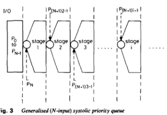
SJJ;E;E. e 214 1 I I I I . Jschemes of these two versions of systolic priority queue were shown in Reference 11. As illustrated there, the new type of queue can be twice as fast as the original queue when completing the same jobs. This new systolic pri- ority queue is well defined, so that it can be easily extended to an N-input systolic priority queue. For prac- tical purpose, N is usually equal to 2*, with b 2 0. The generalised systolic priority queue is shown in Fig. 3. In
. . .
'N-1
Fig. 3
In each stage, the b s t node among (N
+
I) nodes should reside at the first place, e.g.atP,,+,,,.,,
wheninstageiGeneralised (N-input) systolic priority queue
this scheme, the former ith processors, where
0
<
i<
N - 1, are treated as the 1/0 ports, and N nodes are inserted at a time. All nodes are shifted N positions down and the best node in each group of (N+
1) nodes is kept in the first place, among the (N+
1) positions. That is, the best node in positions (N+
l)i-
1 to (N+
1Xi+
1) - 2 should reside at position (N+
l)i - 1, f o ri>
1.The assertion that the single-input queue always deliv- ers the best node is examined in Reference 8, where it is generalised here to any N-input queue whose mechanism is similar to the linear or the new systolic priority queue. Theorem I : In the
SR
systolic priority queue, after any number of insertion or deletion operations, the ith good node is stored in some register A,, where 1 Q k<
2i
- 1C81.
Theorem 2 : For an N-input systolic priority queue, after any number of insertion or deletion operations, the ith
Fig. 2 Systolic priority queue
a Block diagram
b Insertion and shifting down two positions (only relevant parts arc shown)
e Triplet sorting (only relevant parts are shown)
d Extract the k t node and shift up one position (only relevant parts are shown) Purposes of this step
Fig. 2b
Insert two new nodes Shih down two wsitions
Corresponding operations
No
-
Po, N,-
P,; and P,.-
P ,,., , P3,*.-
P.. .-; i B 0 Fig. 2cNode rearrangement
(Triplet soning) P,,., c best(P,,., , P,, , P,,,,}, i b 1 Pa,, P,,,, + t h e other smaller two nodes Fig. W
Enract best node Shift up one position
P,
-
Po, P,,,-
P , , i b 2. Po extracted oute Example of operations in a systolic priority queue In ((1, b) Insert a and b
S-D Shift two positions down SLU Shift one position up E Extract best node TS Triplet sorting
good node is stored in some processor P,, where N 6 k
<
(N+
l)i - 1.Proof of Theorem 2: This theorem is proved by induction as follows. The first several steps can be easily checked by observation, and so we may assume that after m steps of operation the ith good node resides in processor P,, where N
<
k 6 ( N+
1)i - 1. We must then prove that it is still true at the (m+
1)th step.A Assume that the (m
+
1)th operation is an insertion. It can be seen that, although N new nodes are inserted, the best node in the queue will still appear at P,. Now consider the position for the ith good node, where i 3 2. At first, if the ith good node before operation resides in P , , where N<
k<
(N+
1Xi - 1) - 1, then after the new N nodes have been inserted this node will still reside somewhere before the ((N+
1)i - 1)th position; this is alegal position no matter what nodes are inserted (it should be noted that when i = 2, the present case will not
occur). On the other hand, if the ith good node resides in
PI, with (N
+
l)(i - 1) Q k<
( ( N+
l)i - l), then after N new nodes having been inserted and node-rearranging having been completed, this node will reside at position P,, with k equal to (N+
l)i - 1. This is because the other nodes to be compared with this previous ith good node all have ranks higher than i, otherwise Theorem 2 is violated at the mth step. As the new rank of this node will not be lower than i, this is again a legal position.B Assume that the (m
+
1)th operation is a deletion. By the property of Theorem 2, it is easily seen that when the previous best node is deleted and the nodes are rearranged, the new best node will certainly appear at the first position P,. As the previous second good node is originally at P, with N+
1 ,< k 6 ( N+
1)2 - 1, aftershifting all nodes one position up this node will appear somewhere among the first (N
+
1) positions, i.e. at some P, with N<
k<
( N+
1)2-
2. Thus after rearranging nodes, this new best node will certainly reside at P ,.
Now consider the position for the ith good node. As above, we assume that Theorem 2 holds for the previous
m steps, and wish to prove that it still holds at the (m
+
1)th step. At first, if the previous ith (i 3 3) good node resides at P , with N < k<
(N+
l)(i - 1) - 1, then after shifting one position up and rearranging nodes, it can still reside at a legal position. This is because index k of the new position P , is always less than(N
+
l)(i - 1) - 1, which is the largest legal position forthe (i - 1)th good node (new rank for that node). On the other hand, if the previous ith (i 2 3) good node resides at
Pk
with (N+
1Xi - 1) - 2<
k<
( N+
l)i - 1, thenafter shifting one position up and rearranging nodes, that node will appear at P, with k equal to (N
+
1)(i - 1) - 1. This is because, in the rearrangement the nodes to be compared with the previous ith good node are exactly those nodes located originally at some P , with (N+
1)(i - 1) - 2<
k<
(N+
l)i - 1. According to the property of Theorem 2, their ranks are all higher than i.From A and B, it can be seen that Theorem 2 still holds at the (m
+
1)th step. By induction, Theorem 2 is always true after any number of steps of the algorithm.The linear systolic priority queue [8] and the new systolic priority queue [11] may be viewed as special cases of Theorem 2, with N being 1 and 2, respectively. The structure of the case with N equal to 2 will be adopted to implement the algorithm developed in this paper. It is also found that the node arrangement is the key for good nodes to go forwards and the bad nodes to go backwards. If the node rearrangement is inhibited I E E Proc.-Commun., Vol. 141, No. 4, August 1994
somewhere in the queue for each other cycle, then the data flow there will be controlled to allow only backward transmission. This is important for implementing the algorithm introduced here.
3 Erasure-free decoding
In the decoding process, the stack seqential decoder goes back and forth in the code tree to search for the correct path, and so the received sequence must be stored in an input buffer for later processing. If very long searches occur the input buffer will overflow, causing erasure to take place because the data are lost [l]. The decoding effort of a seqential decoder is a random variable with a Pareto distribution, i.e. the probability P(C > N) that the number of computations C exceeds N decreases for large N is proportional to N -?, i.e.
(1) where cp depends on the channel and the rate R only, and C,, is a constant [9, 12, 1.31. Because of this property, no matter how large the computation effort and the input buffer, there are always some code words that cannot be decoded completely, and so the erasure problem due to buffer overflow always exists. In fact, the erasure prob- ability becomes the major limitation on the performance of the code, because the error probability of sequential decoding can be made arbitrarily low [14].
Several methods have been proposed to reduce the erasure probability [7, 161, but the BER performances associated with these methods are also degraded. On the other hand, the generalised stack algorithm (GSA) pro- posed by Haccoun and Ferguson [15] is a method that reduces the erasure problem with no side effects. Further- more, the MSA proposed by Chevillat and Costello [9] is also successful in conquering the problem. It is found that, by using GSA, lower bit error probability and erasure probability can be achieved by extending several nodes at the top of the stack simultaneously. Also, the variability of computation distribution is reduced. Thus better performance is achieved by multiprocessing, using less computation time and less memory. However, the erasure probability can not be completely alleviated with GSA, because the required computation effort is still Pareto-distributed [15].
The MSA is a method for completely erasure-free decoding. Unlike the stack algorithm, it requires a large first stack and many smaller stacks. Furthermore, during the decoding process many tentative results may be reached and be stored in a special register, which always keeps the best decision up to date. The mechanism of the MSA is illustrated in Fig. 4 and briefly described below. 3.1 Mechanism of the MSA
Step 1 : The decoding begins in the first stack. As with the traditional stack sequential decoder, if a terminal node of the tree is reached before the first stack is full, the decoding is completed. However, if the first stack is full before the end of the tree is reached, the top T nodes are transformed to a stack of rank 2, and decoding continues there.
Step 2: Assume that the present stack is of rank i,
i 3 2. As decoding continues, two things may happen (it is important to note that the i is redeclared each time, and should not be confused with the rank of the previous operating stack).
Case A: If the stack is full before the end of the tree is reached, the top T nodes will be transferred to the stack
P(C > N ) = C,,N-'
of rank (i
+
l), and decoding continues there. Go to step 2.Case E: If a terminal node of the tree is reached, this node is treated as a tentative result. The tentative result
extend top node in stack I
decision top T nodes
Output decision
previous stack
stack
Fig. 4 Multiple-stack algorithm
may be stored in a special register, if this result is better or if the register is empty. After that, the present stack will be cleared and decoding continue in the stack of rank ( i
-
1). Repeat step 2.Step 2 will be repeated until the present rank is 1 and
a tentative result is obtained there. That is, a terminal node is reached in the first stack. The only other case to terminate the decoding process is when the computation limit is reached.
In the MSA, every time a stack is full some nodes at the top are transferred to a higher-rank stack newly formed for further extension. Then only subsets of paths in the code tree, which are more likely to be correct, will be searched immediately. Thus, the decoder can go deeper and deeper into the tree after each transfer between stacks, so that the time needed to obtain a tentative decision is shortened. If U denotes the number of stacks formed before the first tentative decision is obtained, then the probability P(u > U) that U exceeds U will decrease exponentially for sufficiently large values of U. Then the number of computations C, executed before stack U overflows is given by [9]
C” =
z1
- 1+
(U-
1)(z - T ) (2) where 2 denotes the size of the higher-rank stack, Z , is the size of the first stack and T is the number of trans- ferred nodes. From these two properties, it follows thatP(C > CO), i.e. the probability that the number of compu-
tations C required for reaching the first tentative decision exceeds C,, will decrease exponentially with C,.
216
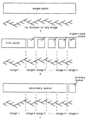
The MSA and the stack algorithm can be illustrated from another viewpoint, as shown in Fig. 5. In the stack algorithm, any proper node can be fetched for further extension, i.e. nodes at any place may ‘flow’ to the branch
single slack
0
higher-rank
stage I SlOge2 slage3 ... stogen-l stogen b primary queue secondory queue I I I I I I I I I I I I I I I
stage I stoge2 s t a g e 3 ... stogen-l s t o g e n
C
Fig. 5
a Stack algorithm b Multiple-stack algorithm
c Compressed multiple-queue algorithm
Decoding trees for algorithms and the memory configuration
extender. In the MSA, however, such flow direction will sometimes be inhibited. For example, when nodes are transferred to higher-rank stacks, decoding is continued there. Thus nodes not transferred will not be processed now, i.e. cannot ‘flow’ to the branch extender. Because of this, when the decoder goes through the decoding tree and reaches stages with fewer nodes (see Fig. 5), decoding in the MSA will become much faster, reaching the end of
the tree quickly. Unlike most methods designed for remedying the erasure problem, the MSA can perform at least as well as the single-stack algorithm and be totally erasure-free [9]. However, it still has the problem of requiring too large a memory and using sorting to rearrange nodes.
Systolic priority queue technology can remedy the sorting problem in the MSA but many queues will be required, thereby causing a serious problem. As every queue needs an 1 / 0 port of several tens of bit-lines per queue, multiple queues will require multiple 1/0 ports, thus leading to tremendous 1 / 0 bandwidth. For example
[SI,
if the size of the newly formed stack is chosen to contain 11 elements, the total stacks needed are about20-30, which means that about lo00 bit-lines will be con-
nected between the memory and the branch extension unit. This requirement for many stacks will become even more serious if more information bits are to be trans- mitted in a frame. Such a result will make layout routeing unrealisable, or else a very complex 1/0 switching control IEE Proc.-Commun., Vol. 141, No. 4, August 1994
mechanism must be incorporated to implemeiit the algo- rithm. Furthermore, only one stack is active at a time for the MSA, and so it will make little difference when paral-
lel processing techniques are adopted. The large memory size required in the MSA, usually in the range of 3000- 5000 [SI, is another problem to implementing the algo- rithm with the systolic priority queue, because the result may become infeasible.
4 ’ Compressed multiple queue algorithm
Because the arrangement of 1 / 0 ports is very complicated and vast memory space is necessary for the MSA, it is impractical to implement it using a systolic priority queue. Here we present an algorithm that saves these two resources while still keeping the desirable performance of the MSA. This is called the compressed multiple queue algorithm (CMQA), as it uses only two queues to process the jobs traditionally processed by multiple stacks.
4.1 Operating principle of CMQA
The key requirement for the MSA to be erasure-free restricts the node searching operation to the deeper subtree, so that it can reach a terminal node quickly. Thus it seems unnecessary to keep the nodes visited for each searching iteration in so many separate stacks (Fig. 5 4 that is, the nodes being processed now can be kept in a small stack, and all nodes already visited may be stored in a large stack.
In the CMQA, when the small stack is full the worst nodes are shifted out and put into the large stack, so that decoding can continue in the small stack. Therefore, the multiple stacks required by the MSA are compressed into two, a small primary stack and a large secondary stack. In such a scheme, the primary stack always operates as the newest stack in the MSA, whereas the secondary
stack always ‘absorbs’ the other stacks which are not cur- rently being used.
Although an extra operation for stack compression is needed in CMQA, this algorithm will be more time- saving than the MSA. This is because, when implement- ing the CMQA with the systolic priority queue, the formation and compression of multiple stacks can be completed at the same time and at the same memory locations. The flowchart of the CMQA introduced below is shown in Fig. 6. For easy comparison with the MSA, the memory used in this algorithm is also referred to as a ‘stack’; however, it is actually a systolic priority queue. 4.2 Mechanism of the CMQA
S t e p 1 : At the beginning the operation is conducted in a large stack. If a terminal node is reached before the stack is full, the decoding results are the same as the single-stack algorithm. If the stack is full, go to step 2.
S t e p 2: Partition the original stack used in step 1 into two parts. Of these, the smaller stack is called the primary stack and contains the nodes from the top of the original stack. The other is called the secondary stack, and is usually much larger than the primary stack.
S t e p 3 : Extend the top nodes in the primary stack and then rearrange the extended new nodes and the nodes in the primary stack. At the same time, rearrange the nodes overflowed from the primary stack and the nodes in the secondary stack. If a tentive decision is obtained in the primary stack, go to step 4; otherwise, repeat step 3.
S t e p 4 : If a tentative decision is obtained in the primary stack, clear the primary stack and then merge the primary stack with the secondary stack. Now, the merged stack is the same as the original stack used in step 1.
S t e p 5 : If the stack is full again, go to step 2. Other- wise, decoding will continue in this stack. The only con-
@
place root node In
t
I
extend top nodes in queues-
I
1
ond secondary queues
secondary queues (to form the original queue)
Fig. 6
I E E Proc.-Commun., Vol. 141, No. 4, August 1994
Compressed-multiple queue algorithm ( C M Q A )
dition for terminating the decoding procedure is when a tentative decision is obtained during step 5, or when it reaches the computation limit.
Examining the procedures for obtaining the first tentative decision in the CMQA and the MSA, it is found that the major operations are conducted in the primary stack (or the highest-rank stack in the MSA). Because of this similarity, it is reasonable that properties 6 and 7 in Reference 9 and eqn. 2 hold for the CMQA (if U in eqn. 2 is replaced by the number of stacks ‘absorbed’ by the sec- ondary stack). Thus the computation effort required by the CMQA to reach the first tentative decision is also exponentially distributed.
4.3 Implementation of CMQA
As the mechanisms in the above five steps are realised with the systolic priority queue, stacks will be referred to as queues in the following; for example, the primary queue and the multiple-queue algorithm (MSA imple- mented with the queues).
At first, if the original stack is replaced by a queue in step 1, the algorithm will become a single-stack algorithm implemented with a queue as in Reference 11. In step 2, the original queue is partitioned into two parts. As all nodes still stay where they are in the original queue, no node transfer or other operations actually occur. There- fore no time or hardware redundancy will be required in the queue partition. The operations in step 2 are similar to the multiple-queue algorithm: that is, a new queue is formed and the top nodes are simultaneous transferred into it. However, the size of this new queue is usually smaller than those used in the multiple-queue algorithm.
In step 3, two things are to be completed: the first is to extend the top node in the primary queue and then rearrange the newly extended nodes and the nodes in the primary queue; and the second is to reorder the nodes overflowed from the primary queue with those in the sec- ondary queue.
Rearranging nodes simultaneously in the secondary queue is of crucial importance for this algorithm, as a terminal node may be obtained in the primary queue at any time and the primary queue will be cleared. Simul- taneously completing these two jobs is difficult for tradi- tional technology, but is easy with the parallel processing capability of the systolic priority queue. Furthermore, no compression or formation of queues actually happens, although some extra control signals are necessary.
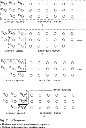
The arrangement of control signals and the partition of queues is illustrated in Fig. 7. At first, as shown in Fig. 7a, to form the primary queue the nodes P , in the orig- inal queue (where k
<
3i+
2, i may be 1 , 2 or some other small integer) are now declared to belong to the primary queue. The other nodes in the original queue then belong to the secondary queue. As the declaration is an abstract idea, the node positions for the primary queue will change with time. For example, when all elements are shifted two positions down, the primary queue is also shifted down, as shown in Fig. 76. Also, when all nodes are shifted one position up, the primary queue and the secondary queue are shifted up, as shown in Fig. 7c. The reason the index k for P , is at first chosen to be k = 3i+
2 is that, shifting two positions down, the primary queue contains exactly triplets of processors (see Fig. 7b), so that the node reordering operation can be conducted independently in both the primary queue and the secondary queue.However, after all nodes have been shifted up, if the node reordering operation is conducted everywhere as 218
usual it becomes meaningless to distinguish the primary queue from the secondary queue. This is because, at this time, if the reordering operation occurs on the boundary between these two queues, e.g. P,-P, in Fig. 7d, nodes in
T - - - T - - -
,poo
p 2 0 p 5 0 ,o o o o o o
l p l o ~ 36 6 0 ’ 0o o o o
o
o
...
I
prlmory queue secondary queue b - - - p o o pzo ~ 5 0 :
o o o
o
o o
‘10 ‘ 3 0 ‘ 6 0 ;o
o
o o o
o
p 4 0 ~ p 7 0o o o o o
o
I - - - - Jprimary queue secondory queue
C - - - lnhlblt signals
poo
p 2 0 p5 0 0 0 0 0 0plo
p 3 0 p6go
0 0 0 0o....
p ~ o ; p 7 0
0 0 0 0 0 - - - Aprimary queue secondary queue
d
Fig. 7 The queues
a Division into primary and secondary queues b Shifting both queues two positions down
e Shifting both queues one position up (bold line indicates the boundary between queues)
d Adding the inhibit signals
the secondary queue may go into the primary queue. Thus the decoding operations will not be confined within a certain subtree, and the decoder may no longer be erasure-free.
To prevent the elements in the secondary queue from getting into the primary queue, the second node reorder- ing operation (i.e. the reordering operation immediately after the ‘shift one position up’ operation) should be inhibited on the boundary between two queues. Inhibit signals are used for blocking the paths for node exchang- ing on the boundaries of queues, as shown in Fig. 7d. By enabling or disabling the inhibit signals, the operations in step 2 and step 3 can be conducted on a systolic priority queue. With such inhibition, nodes in the primary queue can still flow to the secondary queue. (As can be seen, P ,
in Fig. 7d belonging to the primary queue will belong to the secondary queue in Fig. 7c, i.e. in the next iteration.) However, nodes in the secondary queue can no longer get into the primary queue. To merge the queues, as required in steps 4 and 5, the inhibit signals are completely dis- abled and the original queue can work normally again. With these modifications, the CMQA can be easily implemented with the systolic priority queue.
4.4 Memory considerations
As in the MSA, the control of memory space is a problem for the CMQA. In general, the requirements of large I E E Proc.-Commun., Vol. 141, N o . 4, August 1994
memory space are usually found in the traditional stack sequential decoders. However, in a practical stack sequential decoder, the control of memory space is simpler. The penetration depths of a correct path in stacks has been studied in Reference 17. It is found that the correct path usually stays near or at the top of a stack. Thus the possibility of correct node loss can be eliminated with moderate memory size.
Because limited memory is used to implement the CMQA, overflow must be allowed in the original queue to achieve better performance. The original queue works until it is divided into two queues, and so its performance will be determined by the queue division time
&
.
Differ- ent times to divide the original queue will result in quite different performances. For example, if the queue division time&
is set too small, the probability of the correct path not being found will greatly increase and, worse, the correct node may be lost forever. On the other hand, if the orignal queue is maintained for a moderate duration even though it overflows, the BER performance will be better. However, because the computation time is also limited in the CMQA, too-late division of queues will increase the possibility of incomplete decoding. To mini- mise the probability of losing the correct node, and at the same time to avoid incomplete decoding,&
should be chosen carefully so that it is large enough but below some upper bound. This upper bound is derived as follows.Every time the primary queue is formed, N nodes are transferred to the queue. Then, in the worst case, to make a possible correct path in this queue one branch deeper into the tree may require N computations. If nodes in the primary queue are all very close to the root at the begin- ning, then at a conservative estimate it will require N x (depth ofdecoding tree) iterations of computation to reach a tentative decision, i.e. to avoid incomplete decod-
-
lo processor I-
to processor 111 to Drocessor I V0
0
0
0
0
0
0
0
0
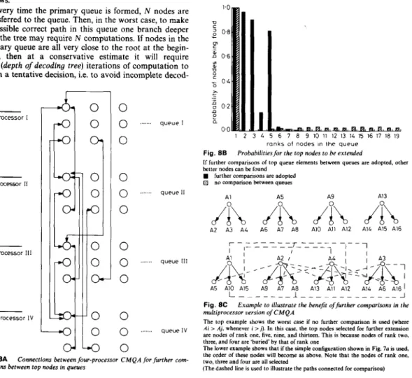
... ... ... q u e u e I q u e u e I1 q u e u e 111 ... q u e u e l V Fig. 8Aparisons between f o p nodes in queues
I E E Proc.-Commun., Vol. 141, No. 4, August I994
Connections between Jour-processor C M Q A for further com.
ing. Accordingly, subtracting this estimated value from the computation limit Climi,, the upper bound of queue division time Td can be determined. For example, in the computer simulations shown later, N = 4 and depth of decoding tree = 500, so that
&
may be chosen to be (C,,,,,- 2000) or smaller.
Multiprocessing is a way to improve memory usage efficiency and increase tree searching speed [lS]. However, it is not easy to adopt in the CMQA, because the systolic priority queue can extract only the best node, but it will require more than one node in a multiprocessor-type CMQA. Our approach to solving the problem is to use one queue for each processor. The multiprocessor-type CMQA is shown in Fig. 8A; four processors and four queues are used in this example. The double arrowed lines shown in the Figure indicate that further comparisons are required between queues. These are of crucial importance if better performance is desired. As illustrated in Fig. 8B, although not all of the best four nodes are obtained in each turn, the performance will be better than when no further comparisons are included. The reason is that good nodes usually fall into some queue, and without these further comparisons other good nodes may be buried under the best node in that queue. With further comparisons, these good nodes can appear at the top of other queues. A graphic example to illus- trate this idea is shown in Fig. 8C. Computer simulations
1.0 V
2
0 8-
m c 2 0 6 YI 01 U 0 4 A I -z
0 2 0 a 0.0 I 2 3 4 5 6 7 8 9 10 11 12 13 14 15 16 17 18 19 r a n k s of n o d e s in t h e q u e u e Fig. 8BIf further comparisons of top queue elements between queues are adopted, other better nodes can be found
H further comparisons are adopted
Probabilitiesfor the top nodes to be extended
no comparison between queues
A1 A5 A9 A1 3
A2
A
A3 A4 A6/I\
A7 A8 A10/I\
All AI2 A14/l\
A15 A16Fig. 8C Example to illustrate the benefit offurther comparisons in the multiprocessor version o J C M Q A
The top example shows the wont case if no further comparison is used (where Ai > Aj, whenever i > j ) . In this case, the top nodes selected for further extension are nodes of rank one, five, nine, and thirteen. This is because nodes of rank two, three, and four are 'buried' by that of rank one
The lower example shows that if the simple configuration shown in Fig. l a is used, the order of these nodes will become as above. Note that the nodes of rank one, two, three and four are all selected
(The dashed line is used to illustrate the paths connected for comparison)
prove that good performance can be achieved with this scheme.
4.5 Speed considerations
The following compares the operation speeds of the CMQA and the MSA. As some circuit design tricks are adopted in the implementation of a systolic priority queue, and there is still no practical implementation for the MSA, some assumptions are necessary to make the following comparisons more fair. First the node reorder- ing operation is extracted from the integrated operation
of a systolic priority queue. This is because the speed of
this operation is crucial for the total speed of a single- stack algorithm and the MSA. However, it is important to note that, for a real VLSI circuit of a systolic priority queue, all node reordering and node shifting operations are conducted in parallel with the best-node retrieving (READ) and the new-node insertion (WRITE) oper- ations. That is, only the time delay for one READ and one WRITE is required during a decoding cycle for a systolic priority queue. Secondly, it is assumed that the sorting operation in the MSA is replaced by the best node searching operation. Furthermore, it is assumed that the comparators used in the MSA are as many as required, although in fact only one processor is usually used. Using the comparators to find the best of N nodes Dog, N1 iterations are required, where [ a ] is the minimum integer greater than a. Thus 2*rlog, 31 iter- ations are required for the CMQA. For the MSA, [log, Z i l iterations are required, where Zi is the size of the ith rank stack that the MSA is working on. The oper- ations required for the CMQA and the MSA during one decoding cycle are shown in Table 1. It is found that the Table 1 : Operations for the CMOA and MSA during one decoding cycle
CMQA CMQA MSA MSA
(when the (when using (when using (when using queue is the high-rank the first the high-rank not divided) memory) stack) memory) 1 READ l R E A D l R E A D 1 READ 1 WRITE 1 WRITE 1 WRITE 1 WRITE 4 comparisons 4 comparisons 10 comparisons 4 comparisons
(size of the first (size of the high stack=l000) rank s t a c k = l l ) 11 comparisons
(size of the first stack = ZOO01
MSA is slower than the CMQA even with similar imple- mentation technology. If the practical circuit is taken into account, the speed of the CMQA will be faster (only one READ and one WRITE).
5 Computer simulations and discussion
The performance of the CMQA is evaluted by computer simulation. The MSA was also simulated under identical conditions for comparison. A convolutional code with rate R equal to 1/2 and constraint length L equal to 15 was used, where the generator polynomials were
Gl(X) = 1
+
X+
X4+
X 6+
X7+
X 8+
X'O+
X"+
X I 3+
X I 5+
X I 2+
X14+
X'5G 2 ( X ) = 1
+
X 3+
X6
+
X7
+
X 8+
X I oAll coded data sequences were transmitted through the same binary symmetric channel with white Gaussian noise; 500 bits per frame were transmitted.
220
The performances of the CMQA decoder with differ- ent queue division time
&
and memory size are illus- trated in Fig. 9A. Unlike most stack sequential decoders,10-2. P, 10-3. 1 0 . ~ - Fig. 9A CMQA -a- curw 1 -0- curve2
Influence of queue division time Td on the performance of
(SO0 elements; '& = n00)
(1000elements; '& = Ioo0)
(loo0 elements; '& = 1800) (800 elements; q = 2100) (loo0 elements; '& = 2400)
(800 elements; '& = 3200) -A- N N e 3
-A- curve4
-.-
curve5-0- curve6
the CMQA decoder with a larger memory does not always perform better than those with a smaller memory. For example, the performance shown by curve 2, which corresponds to a decoder with lo00 queue elements, was poorer than those shown by curves 4 and 6, which correspond to the decoders with 800 queue elements. This illustrates that the queue division time
'&
will influ- ence the BER performance. In curve 2, queue division took place just after the queue overflowed. However, in curves 4 and 6, queue division took place after the queue had overflowed thousands of times. As shown in the pre- vious Section, the upper bound to ensure erasure-free decoding in these simulations was 2096(3 = Climit- N*Depth of the coding tree, where Climir was 4096, N was 4 and depth of the coding tree was 500). In curve 6,
&
was much larger than this, so that erasures sometimes occurred. In curve 5, although
&
was slightly larger than the bound, no erasure occurred during the simulation. This is because the bound was derived under the worst case; in most cases this would not happen.The performance of the multiprocessor-type CMQA is shown in Fig. 9B, where the performance of the single- processor CMQA shown by curves 4 and 5 in Fig. 9A is duplicated for comparison. A four-processor CMQA is used here. As each processor corresponds to one systolic priority queue, four systolic priority queues are used. Using the same the total memory, the size of each queue is one-quarter of that in the single-processor-type CMQA. In a multiprocessor type CMQA, the deter- mination of the queue division time is more important than in the single-processor CMQA. If the queue division time is selected to be equal to the queue overflow time, as shown by curve 1 in Fig. 9B, the performance will become very poor. The performances shown in curves 3 and 5 are good, but erasures sometimes occurred because I E E Proc.-Commun., Vol. 141, No. 4, August 1994
10-1- 10.2. 10-3- pe 10-6- 10-5- 10-6 curve 1 (loo0 elements; Td = 250) curve a4
(single processor 800elements; 7, = 2100)
I
3 4 5 6 7
curve a5
(single processor loo0 elements; 7 , = 2400) curve 2 10-2 1 0 . ~ - Pe 10-6 (800 elements; 7, = 2000) curve 4
(loo0 elements; '& = 2000) curve 3 (800 elements; 7 , = 3400) curve 5 (1000elements; 7, = 3500) - -
single-processor-type CMQA, it is found that the multi- processor CMQA can achieve better BER performance with the same memory sizes.
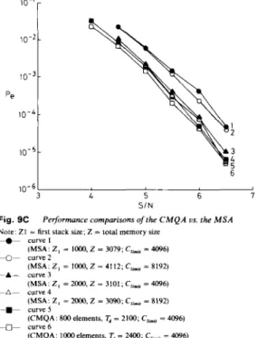
Comparisons between the performances of CMQA and MSA are illustrated in Fig. 9C. Curves 2 and 4 in Fig. 9B are chosen for these comparisons, because they are truly erasure-free. In the MSA simulated here, the first stack is chosen to contain either 1000 or 2000 ele-
ments, and the size for each higher-rank stack is 11 ele- ments. The same computation limit as that in the CMQA (Climir = 4096) or larger (Climir = 8192) is used. It is seen in Fig. 9C that the size of the first stack in the MSA has a great influence on its performance. The performance of the MSA with the first stack size equal to 2000 is better than that of the MSA with the first stack size equal to 1000. For example, when S / N is at 6 dB, the MSA with its first stack equal to 2000 can achieve a bit error rate of 7.35 x lo-*, but at the same S/N the MSA with its first stack equal to 1000 can only achieve 2.32 x lo4.
From Fig. 9C it is obvious that the CMQA can achieve better performance than the MSA, using much
t
4 5 6 7
S I N
Fig. 9C
Note: ZI = first stack size; Z = total memory size
-e- curvel
-0- curve2
---A- curve 3 -A- curve4
Performance compurisons of the C M Q A us. the M S A (MSA: Z , = 1000, Z = 3079; C,i,, = 4096) (MSA: Z , = 1000,Z = 4112; C,,,,, = 8192) (MSA: Z , = 2w0, Z = 3101; CLi,, = 4096) (MSA: 2 , = 2Mx), Z = 3093: C,$,,, = 8192) (CMQA: 800 elements, 7 , = 2100; C,,,,, = 4096) (CMQA: I000elements. 7, = 2400; C,.,, = 4096)
-.-
curve5 -0- curve6Table 2: Performance comparisons for CMOA VS. MSA on the AWGN channel with (2.1, 12) convolutional code G = 142554.773041. d,,,, = 16
C M Q A C M Q A M S A M S A M S A M S A Z,=lOOO z , = 2 0 0 0 Z,=lOOO z , = 2 0 0 0 Computation limit 4096 4096 4096 4096 81 92 81 92 Maximum memory used 800 1000 3112 4035 3244 41 56 S / N = 6 d B 6.7 10-5 3.7 x 10⁻⁵ 9 x 10⁻⁴ 9 x 10⁻⁵ 7.2 x i o - 1 9.5 x 10⁻⁵ S I N = 5.5 dB 8.5 10-4 7.3 x 1 0 - 4 5.2 x 10⁻³ 1.6 x 10⁻³ 3.66 x 10⁻³ 1.3 x 10⁻³ S I N = 5 dB 3.6 x 7.6 x 2.1 x 10.' 8.2 x 1.0 x l o - * 6.6 x SIN = 4.5 dB 1.3 x 1.0 x l o - * 7.0 x l o - * 3.0. 6.6 x 3.6 x 10.' S/N = 4 dB 6 , 0 x l O - ' 4 . 8 x l O - ' 1.1 " l o - ' l . O x l O - ' 1.1 x 1 0 - l l . O x l O - '
Table 3: Performance comparisons for CMQA vs. MSA on the AWGN channel with (4,l. 12) convolutional code G = 144624,52374,66754,735341, d,,- = 33
C M Q A C M Q A M S A M S A M SA M SA
z.
= 1000 2. = 2000z.
= 1000z.
= 2000Computation limit 4096 4096 4096 4096 81 92 81 92
Maximum memory used 800 1000 2980 3892 1352 2000
S I N = 6 dB 4.0 x 3.4 x 4.4 x l o - ' 2.66 x 4.0 X l o - ' 2.83 x l o - ' S I N = 5.5 dB 6.0 x 5.5 x 8.5 x lo-: 6.3 x lo-: 7.0 x 5.5 x 10.' S I N = 5 dB 1 . 2 7 ~ 1 0 - 5 9 . 4 ~ 1 0 - 6 1 . 3 3 ~ 1 0 - 1 . 1 6 ~ 1 0 - 1.21 . i o - 5 1.11 ~ 1 0 - 5 S I N = 4.5 dB 2.0 10-5 1.9 x 10⁻⁵ 2.6 x 10⁻⁵ 2.3 x 10⁻⁵ 2.45 x 10⁻⁵ 1 . 9 5 ~ 10-5 S / N = 4 d B 4.57 10-5 2.9 x 10⁻⁵ 1.1 x 10⁻⁴ 8.75 x 10⁻⁵ 3.2 x 10⁻⁵ 2.15 x 10⁻⁵
Table 4: Performance comparisons for CMOA vs. MSA on the AWGN channel with (4. 3. 9) convolutional code
CMQA CMQA M SA MSA M SA MSA
Z.=lOOO z.=2OOo Z.=lOOo z.=2000
Computation limit 4096 4096 4096 4096 81 92 81 9 2
Maximum memory used 800 1000 241 9 3221 2375 3276
S / N = 7 d B 7.8 x 7.25 x 2.33 x 1.67 x 2.3 x 10.’ 1 . 4 5 ~
S/N = 6.5 dB 2 . 3 x l o - * 2.1 x 6 . 0 x l o - * 3.6 x l o - * 6.45 x l o - * 4.25 x
SIN = 6 dB 5.7 x 5.2 x 1 . 3 x 10.’ 9 . 2 ~ 10.: 1.27 x l o - ’ 1.06 x l o - ’
SIN = 5 . 5 dB 1 . 2 8 ~ 1 0 - ’ 1 . 2 2 x l O - ‘ 2 . 0 9 ~ 1 0 - ’ 1 . 6 9 ~ 1 0 - 2 . 2 5 ~ 1 0 - ‘ 1 . 7 7 x 1 0 - ’
less memory For example, when S/N is equal to 6 dB, with only 800 queue elements, the CMQA can achieve a bit error rate of 5 x At the same S/N, with a first stack of size equal to 2000 and a total memory size equal to 4122, the MSA can only achieve a bit error rate of Some simulation results of the other three convolu- tional codes are included in Tables 2-4. The CMQA in all these tables are implemented in a four-processor scheme. In Table 2, a (2, 1, 12) convolutional code is used. It is found that, except for some degradation, the BER performances of the CMQA and the MSA are similar to those for a (2, 1, 15) convolutional code. This is because the possibility of using higher-rank memory (i.e. the possibility that erasure may occur in a single-stack algorithm) is similar for both codes at those S/N ratios. In Table 3, a (4, 1, 12) convolutional code is used. Because this is a powerful code, the BER performance is much better. Furthermore, the performances of the CMQA and the MSA are quite close. This is reasonable, as the possibility of using higher-rank memory is very low for this code at those S/N ratios. Under these condi- tions, both the CMQA and the MSA operate like a single-stack algorithm, and the minor different in BER performances are due to different memory size and number of processors used. In Table 4, a (4, 3, 9) convol- utional code is used. For this code at these S/N ratios the frequency of using higher-rank memory is quite high for both the CMQA and the MSA. From Table 4 it is found that the BER performance for the CMQA is half or one- third of that for the MSA. As the bit errors here are gen- erated mainly in those cases where higher-rank memories are used, the improvement that the CMQA can achieve over the MSA is clear. Thus the CMQA can achieve better BER with less memory than the MSA and is more I/O efficient.
7.35 x 10⁻⁵.
6 Conclusion
The systolic priority queue has been shown to be a prom- ising technique for implementing a high-speed single- stack sequential decoder. A compressed multiple queue algorithm (CMQA) is introduced to implement an erasure-free decoder with the systolic priority queue. Owing to the two-stack scheme proposed for the CMQA, the 1/0 is much simpler than that required in the multiple-stack algorithm. Furthermore, except for some
extra control signals required, the implementation for the CMQA with the systolic priority queue is as easy as that for the traditional single-stack algorithm. Computer simulations show that the CMQA can achieve similar performance to that of the MSA, using only one-quarter to one-third the memory space.
7 References
1 LIN, S., and COSTELLO, D.J. Jr.: ‘Error control coding: funda-
mentals and applications’ (Prentice-Hall, New Jersey, 1983)
2 VITERBI, A.J., and OMURA, J.K.: ‘Principles of digital communi- cation and coding’(McGaw-Hill, 1979)
3 CLARK, G.C., and CAIN, I.B.: ‘Error-correction coding for digital communications’ (Plenum Press, New York, 1981)
4 CAIN, J.B., CLARK, G.C. Jr., and GEIST, J.M.: ‘Punctured convol-
utional codes of rate (n - l)/n and simplified maximum likelihood
decoding’, I E E E Trans., 1979, IT-25, pp. 97-100
5 HACCOUN, D., and BEGIN, G.: ‘High rate punctured convolu-
tional codes for Viterbi and sequential decoder’, I E E E Trans., 1989, COM-37, pp. 1113-1125
6 ZIGANGIROV, K.: ‘Some sequential decoding procedures’, Probl. Peredachi In$, 1966,2, pp. 13-25
7 JELINEK, F.: ‘A fast sequential decoding algorithm using a stack’, IBM J. Res. Deu., 1969,13, pp. 675-685
8 CHANG, C.Y.: ‘Systolic array architecture for convolutional decod- ing algorithms: Viterbi algorithm and stack algorithm’ (PhD disser- tation, University of California, Los Angeles, 1986)
9 CHEVILLAT, P.R., and COSTELLO, D.J. Jr.: ‘A multiple stack algorithm for erasure-free decoding of convolutional codes’, I E E E
Trans., 1977, COM-25, pp. 1460-1470
10 CHANG, C.Y., and YAO, K.: ‘Systolic array architecture for the sequential stack decoding algorithm’, Pror. S P I E , 1986, 6%. pp.
1%-203
1 1 LAVOIE, P., BELZILE, J., TOULGOAT, M., HACCOUN, D., and
SAVARIA, Y.: ‘VLSI design of a systolic priority queue chip for sequential decoders’. Proc. 1988 Canadian Conf. VLSI, Halifax, Nova Scotia, Canada, 1988, pp, 1-9
12 SAVAGE, I.E.: ‘Sequential decoding - the computation problem’, Bell Syst. Tech. J . , 1966.45, pp. 149-175
13 FORNEY, G.D.: ‘Convolutional codes 111: sequential decoding’, lrfo. and Control, 1974,25, pp. 267-297
14 FANO, R.M.: ‘A heuristic discussion of probabilistic decoding’, I E E E Trans., 1963, IT-9, pp. 64-74
15 HACCOUN, D., and FERGUSON, M.J.: ‘Generalized stack algo- rithms for decoding convolutional codes’, l E E E Trans., 1975, IT-21,
pp. 63&651
16 FORNEY, G.D., and BOWER, E.K.: ‘A high speed sequential decoder: prototype design and test’, I E E E Trans., 1971, COM-19,
pp. 821-835
17 GOULD, T.M., and HARRIS, J.H.: ‘Single-chip design of bit-error-
correcting stack decoders’, I E E E JSSC, 1992, SC-27, pp. 768-775 18 GUIBAS, L.J., and LIANG, F.M.: ‘Systolic stacks, queues, and
counters’, 1982 Conference on Advanced Research in VLSI, MIT
19 LEISERSON, C.E.: ‘Systolic priority queue’. Proc. of Caltech Conf.
on VLSI, 1979