2344
J. Electrochem. Soc., Vol. 138, No. 8, August 1991 9
The Electrochemical Society,Inc.
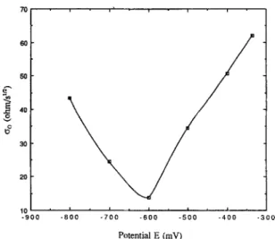
7 0 , I 6 0 5O v 30 20 10 t i i i i - 9 0 0 - 8 0 0 - 7 0 0 - 6 0 0 - 5 0 0 - 4 0 0 - 3 0 0 Potential E ( m V )Fig. 5. Warburg coefficient-potential curve for preoxidized Ni in fused Na2S04 at 1200 K.
irreversible process, % a n d Ro/s can be expressed as fol- lowing R T % - [ 2 ]
n2F2~ 2~o~
Ro/s
--R T n2FaC~ok~h~ exp (-~<~)where C~o a n d Do are the b u l k concentration a n d the diffu- sion coefficient of $20~- in the melt, respectively, (~ is the cathodic transfer coefficient, k~h is the rate constant of the cathodic reaction, a n d ~b = (nF/RT)(E - Eo). R, T, n, a n d F have their usual meanings. Since the salt melt was not ex- posed to the SO2-O2 gas m i x t u r e u n t i l the e x p e r i m e n t started, the b u l k concentration of $20~- (dissolved SO3) was low at first. As the i m p e d a n c e m e a s u r e m e n t s pro- ceeded with increasing polarization, the dissolution of SO3 c o n t i n u e d a n d the b u l k concentration of $20~- gradually increased. Thus, instead of a constant value, a decreasing % was observed. The c h a n g i n g b u l k concentration of $20~-, coupled with the overpotential term exp (-~(h), also
caused Ro/s to decrease as the cathodic polarization in- creased, u n t i l the reaction became diffusion limited.
Conclusions
Double layer capacitance in a fused Na2SO4 film on a preoxidized Ni electrode was measured by electrochemi- cal i m p e d a n c e spectroscopy. A m a x i m u m capacitance was observed at a potential of -0.6 V (vs. Ag/Ag2SO , reference electrode), which, based o n the polarization resistance, dif- fusion impedance, a n d p o t e n t i o d y n a m i c polarization measurements, resulted from the additional c o n t r i b u t i o n of a faradaic reaction. The decrease in polarization resist- ance a n d diffusion i m p e d a n c e with increasing polarization potential was attributed to the overpotential effect and the t i m e - d e p e n d e n t dissolution of SO~. Application of the ac i m p e d a n c e t e c h n i q u e is ideal in this case, because the sys- t e m has b e e n thoroughly studied (9) a n d an equivalent cir- cuit u n a m b i g u o u s l y decided.
Acknowledgments
This research was sponsored b y the National Science F o u n d a t i o n u n d e r G r a n t No. DMR 8620311. Critical reading of this m a n u s c r i p t by R. A. Rapp is gratefully ac- knowledged.
Manuscript s u b m i t t e d Dec. 10, 1990; revised m a n u s c r i p t received March 11, 1991.
The Ohio State University assisted in meeting the publi- cation costs o f this article.
R E F E R E N C E S
1. I. L. Cooper, J. A. Harrison, a n d D. R. Sandbach, Elec-
trochim. Acta,
23,
527 (1978).2. I. L. Cooper a n d J. A. Harrison, ibid., 29, 1147 a n d 1165 (1984).
3. W. Wilhelmsen a n d T. Hurlen, ibid., 32, 95 (1987). 4. C. Clerc a n d D. Landolt, ibid., 33, 859 (1988).
5. M. Weidenauer a n d K. G. Weft, Ber. Bunsenges. Phys.
Chem., 92, 1368 (1988).
6. A. D. Graves a n d D. I n m a n , J. Electroanal. Chem., 25, 357 (1970).
7. K. R. Painter, P. Ballone, M. P. Tosi, P. J. Grout, a n d N. H. March, Surf. Sci., 133, 89 (1963).
8. H. Shih a n d H. W. Pickering, This Journal, 134, 1943 (1987).
9. Y. M. Wu a n d R. A. Rapp, This Journal, Accepted for publication.
10. M. Sluyters-Rehbach a n d J. H. Sluyters, in "Electro- analytical Chemistry," Vol. 4, A . J . Bard, Editor, Marcel Dekker, New York (1970).
Enhanced Metal Recovery in Fluidized Bed Electrodes with a
Fin-Type Current Feeder
Shi-Chern Yen* and Ching-Yih Yao
Department o f Chemical Engineering, National T a i w a n University, Taipei, Taiwan, China
ABSTRACT
A rectangular side-by-side fluidized bed electrode for metal recovery from dilute copper solutions was investigated. Because the contacts b e t w e e n fluidized particles and current feeders are particularly important, fin-type c u r r e n t feeders were used to e n h a n c e the deposition rate. Polarization curves with a fin-type c u r r e n t feeder were measured at various Rey- nolds n u m b e r s . It is shown in the experiments that fin-type current feeders provide higher deposition rates for the same electrode potential t h a n planar current feeders in fluidized bed electrodes.
Fluidized bed electrodes have been proposed since 1966 (1, 2). The conductive particles as electrodes are fluidized i n the cell by flows of electrolytes, a n d electrochemical re- actions proceed on electrode surfaces by applying electri- cal voltage to the cell. The fluidized bed electrode could re- sult in high productivity, even in the condition of low current densities d u e to its high specific surface area. Be- cause of the particle m o t i o n in fluidized bed electrodes, ag-
* Electrochemical Society Active Member.
glomeration due to metal deposition is avoided, u n l i k e in packed bed electrodes (3, 4), a n d this also allows continu- ous removal of metals by i n t r o d u c i n g small particles at the top of the bed, with the withdrawal of grown particles at the bottom. Several potential applications have been studied (5-8), b u t fluidized bed electrodes are especially i m p o r t a n t in metal recovery where the m a i n application can be expected (9-12).
Many f u n d a m e n t a l investigations have been carried out a n d have concluded that the electrochemical behavior of
J. Electrochem. Soc., Vol. 138, No. 8, August 1991
9 The Electrochemical Society,Inc.
2 3 4 5 fluidized bed electrodes is affected by bed expansion, bedheight or bed thickness, current density, and the reactant concentration in the electrolyte (10, 11, 13, 14), and a m o n g them, bed e x p a n s i o n is a particularly i m p o r t a n t factor. It has b e e n found that in the direction normal to the current feeder, the active regions are near the current feeder as well as the m e m b r a n e , and t h e r e exists an anodic region in w h i c h the potential of c o n d u c t i v e particles is higher than that of the electrolyte phase, and the region will be en- larged by increasing bed e x p a n s i o n s (13). This p h e n o m e - n o n arises from discontinuity of the particle phase, in w h i c h it cannot be regarded as equipotential any more.
As a matter of fact, effective solid conductivity is the key point of e l e c t r o c h e m i c a l behavior in fluidized bed elec- trodes. Because particulate electrodes contact with each other instantaneously, the order of m a g n i t u d e of the effec- tive c o n d u c t i v i t y is the same as that of the electrolyte phase (15, 16). Theoretical estimation of effective conducti- vities is based on w h a t m e c h a n i s m of charge transfer is as- sumed. There are a few m e c h a n i s m s proposed, and two of the m o s t i m p o r t a n t are described briefly as follows:
1. Collision m e c h a n i s m (17, 18).--The electrical double layers of particles are charged while contacted with cur- rent feeders or other particles w h i c h carry different charges, and are t h e n m o v e d to other positions for being discharged by either sharing with other particles or by e l e c t r o c h e m i c a l reactions.
2. C o n d u c t i v e m e c h a n i s m (15, 19).--Aggregated parti- cles in the fluidized bed contact with others to form chains w h i c h m a y t o u c h either the current feeder or other chains, and charges will pass t h r o u g h the chains by electronic conduction. Because the chain exists for a short time pe- riod and t h e n is destroyed and reformed as another parti- cle chain, potential fluctuation has been observed (20). The aggregated particle chains can be classified by w h e t h e r or not t h e y t o u c h current feeders. The chains touching cur- rent feeders are called " m o n o p o l a r , " and those not touch- ing current feeders are called "bipolar." Either reduction or oxidation reactions can occur on the surface of a mono- polar particle, but both of t h e m occur on the opposite side surfaces of bipolar particles at the same time, respectively. L e e et al. (21) h a v e m e a s u r e d the bipolarity in fluidized b e d electrodes. S a b a c k y and Evans (15), and H u h and E v a n s (22) h a v e c o n c l u d e d t h a t t h i s c o n d u c t i v e mecha- n i s m is the m o s t probable in their e x p e r i m e n t a l investiga- tions.
In our investigations the m e c h a n i s m of charge transfer is c o n s i d e r e d as a c o n d u c t i v e m e c h a n i s m , and we tried to r e m o v e the limitation of bed e x p a n s i o n in the applications of fluidized bed electrodes by the appropriate design of the current feeder, for e x a m p l e using a fin-type current feeder. Macroscopic p e r f o r m a n c e s of the fluidized bed electrodes with a fin-type current feeder have been carried out by m e a s u r i n g their polarization curves. T h e cell p e r f o r m a n c e of cupric ion r e m o v a l from dilute solutions in fluidized bed electrodes was also investigated by circulating the electro- lytes t h r o u g h the fluidized cell. Concentration of cupric ion in the reservoir was m e a s u r e d with the deposition time. It was found in our m e a s u r e m e n t s that the fluidized electrolytic cell with a fin-type current feeder can offer higher current densities and give broader allowance of bed expansion.
Experimental
E x p e r i m e n t a l a p p a r a t u s . ~ T h e rectangular side-by-side
fluidized bed cell is depicted in Fig. 1. The cell is separated into u p p e r and lower parts. The lower part is the electro- lyte entrance and flow d e v e l o p i n g region, which consists of glass beads of 1.5 m m diam. The u p p e r part is the region of the electrolytic cell and is separated into two sections by an anion e x c h a n g e m e m b r a n e (Asahi Glass Company). The left side is the cathodic part, containing a current feeder with copper particles ( G r e d m a n n Company), sieved into the size range of 425-600 ~m as cathodes. The average d i a m e t e r of c o p p e r particles is 512 ~m and the unfluidized bed porosity is 0.688. The right side is the anodic section w h i c h is packed with platinized titanium screens, where o x y g e n evolution occurs. The length of both u p p e r and lower parts is 22.5 cm, with 3.8 c m in side width, and 2 c m
9 10
I
5 ~2
I
1: c a t h o d i c z o n e 2: a n o d i c z o n e 3: d i s t r i b u t o r 4: a n i o n e x c h a n g e m e m b r a n e 5,6: c u r r e n t f e e d e r s 7: c a t h o l y t e i n l e t 8: a n o ] y t e ~alet 9,10: e l e c t r o l y t e o u t l e tFig. 1. The fluidized bed cell.
in depth. Anolytes and catholytes were p u m p e d into the cell at the l o w e r parts respectively from b o t h reservoirs, and the anolytes contained sodium sulfate 0.8M. The cath- olytes consisted of cupric sulfate in the range of several mM, as well as supporting electrolytes of sodium sulfate 0.8M, and buffers to control pH in a range b e t w e e n 3 and 4. The solution c o n d u c t i v i t y is 0.065 (ll cm) -1. All c h e m i c a l s m a d e b y M e r c k C o m p a n y are analytical grades.
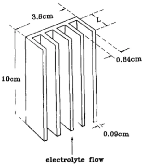
A fin-type current feeder m a d e of titanium is shown as Fig. 2. T h r e e different current feeders were used in the ex- periments. Two of t h e m were fin types, and the length L of fins was 0.7 and 1.2 cm respectively; they were respec- tively called short-fin and long-fin current feeders for con- venience. T h e other one was a planar current feeder. Each of the fin-type current feeders had five fins with a thick- ness of 0.9 mm. Because the fluidized bed length in our ex- periments n e v e r e x c e e d e d 5.5 cm, about half the surface area of the current feeder was m a s k e d to m i n i m i z e the area e x p o s e d directly to the electrolytes. A copper wire, func- tioning as the reference electrode, was placed above parti- cle beds near the m e m b r a n e . A potentiostat/galvanostat, HA320 from H o k u t o Penko, Limited, was used to supply electric p o w e r and to control potentials b e t w e e n w o r k i n g and reference electrodes.
E x p e r i m e n t a l procedures.--Steady-state polarization
curves of the fiuidized bed electrodes with t h r e e types of current feeders w e r e m e a s u r e d at various Reynolds num- bers (Re = vdp/~), w h i c h is based on the particle's diameter dp, fluid superficial velocity v, and kinematic viscosity v. The electrolytes were circulated from a reservoir of 40 li- ters, in w h i c h the variation of the concentration can be ne-
/ 3.8cm -~ - ' ~ .',1, " \ ~ " " ' ~ 0 . 8 4 c m 10cm I O.09cm
1
e l e c t r o l y t e f l o w2 3 4 6
J. Electrochem. Sac., Vol. 138, No. 8, August 1991 9
The Electrochemical Society, Inc. glected. The circulating operation was carried out at a con-trolled potential, and concentration of cupric ion in the reservoir was d e t e r m i n e d by a s p e c t r o p h o t o m e t e r (Miltin- roy Company, Spectronic 601). Wavelength was set on 810 nm. Copper particles w e r e treated with acetone and di- luted nitric acid before being used, and the catholytes in the reservoir were purged by high-purity nitrogen before and during the experiments.
Results and Discussion
P o l a r i z a t i o n curves.--Polarization curves of fluidized bed electrodes with the planar current feeder measured at various Reynolds n u m b e r s (Re = vdp/v) are shown in Fig. 3. The current densities calculated in all figures are based on the e x p o s e d surface area of the planar current feeder, 12.16 cm ~ (3.2 • 3.8 cm), w h i c h is covered by cop- per particles before being fluidized (the initial height of bed: 3.2 cm; width: 3.8 cm). The concentration of cupric ion used in the e x p e r i m e n t s was 0.02M. The parameter e, appearing in Fig. 3, represents the porosity of the fluidized bed and the unfluidized bed porosity was m e a s u r e d at 0.668. As s h o w n in Fig. 3, the current densities with the planar current feeder increase with the applied potentials. There is no limiting-current plateau observed, i.e., the cur- rent flows in the fluidized bed electrodes at the range of ap- plied voltages are not controlled by mass transfer. The same result was also obtained by F l e i s c h m a n n and Kelsall (13), who e x p l a i n e d that n o n u n i f o r m potential distribution arose from the low effective conductivity of fluidized bed electrodes. Thus, polarization curves were almost linear in this situation. A r e m a r k a b l e result can be seen in Fig. 3 in that the current densities of polarization curves do not rise as increasing Reynolds n u m b e r s (Re = v d J , ) , which can be related to bed expansions (i.e., the ratio of increased bed length by fiuidization to the initial bed length). The same result is also observed in Fig. 4, w h i c h shows polar- ization curves of fluidized b e d electrodes with the short-fin current feeder. B u t as shown in Fig. 5, the current densi- ties of polarization curves with the long-fin current feeder are raised higher as increasing Reynolds n u m b e r s or bed expansions. It has to be pointed out here that it can further be operated at bed expansions higher than 48%. It is found that the long-fin current feeder offers the best per- formance.
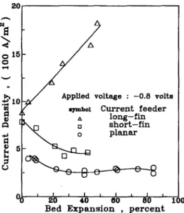
Effects o f bed e x p a n s i o n . - - I t can be found in Fig. 3-5 that the long-fin current feeder gives higher current densities at the same applied potential, and the short-fin current feeder does not offer obvious e n h a n c e m e n t in current densities at the same condition. Figure 6 shows current densities vs. bed expansions for these t h r e e current feeders at an ap- plied voltage of -0.8 V, and there is a significant difference
15 0 0 10 ga @ 5 rj 0 0.0 Re b e d o eymbol ( l - e ) e x p a n s i o n ( ~ ) / o 2 3 9 , 9 " r 4 0 21 / 6 8 4 2 [] 49 2 7 0 / / t I t I t I 0.5 1.0 1.5 P o t e n t i a l , ( - v o l t s )
Fig. 4. Polarization curves with the short-fin current feeder.
of deposition rates b e t w e e n the long-fin current feeder and the other two. As s h o w n in Fig. 6, the current densities de- crease as bed e x p a n s i o n s increase by using the planar and short-fin current feeders, but the current density by the short-fin current feeder is higher than that by the planar current feeder, and asymptotic current densities seem to be reached at higher bed expansions. These asymptotic current densities s e e m to be c o n t r i b u t e d mostly from the particles near the surface of the current feeders, because the ratio of surface area of c u r r e n t feeders, short-fin to pla- nar, is 2.47, and the ratio of a s y m p t o t i c current densities short-fin to planar, is 1.5. F u r t h e r m o r e , our e x p e r i m e n t a l results (23) indicated that the limiting current densities of a fluidized cell w i t h inert particles, w h i c h using the planar and short-fin current feeders, were in the range of 70-100A/m 2 and 100-200A/m 2, respectively; they were close to t h e a s y m p t o t i c current densities. The current den- sities with the long-fin current feeder are raised as increas- ing b e d expansions, and t h e y are m u c h higher than those of the other two types.
The contribution of metal deposition on the current feeder itself could also be investigated. In our experimen- tal results the c o n t r i b u t i o n of the long-fin current feeder it- self to the total current w a s m e a s u r e d b y the anodic disso- lution of the current feeder individually after the m e t a l deposition w a s c o m p l e t e d . It w a s f o u n d that less than 5 %
o o 8'] I=1 I.,i rj
oO'
b e d e x p a n s i o n (~) o 11 4 ~ " x 19 9 / ,~ 30 ~e J ~+
6 6 61/w/
D 78 74/ f l
, 3 9 3 0 p / A 0 5 2 4 8 / / ~i '
t I = I f I 0.5 1.0 I. P o t e n t i a l , ( - v o l t s ) Fig. 3. Polarization curves with the planar current feeder.b e d
so
72 ~
J
~ 40 19 ~" O 51 26 / o a 24 4 9 ~ o o 18 O / j , "~-20
9 o 10 N r ~ R~; I I r I I I 0.6 1.0 1.5 P o t e n t i a l , ( - v o l t s ) Fig. 5. Polarization curves with the long-fin current feeder.J. Electrochem. Soc.,
V o l . 1 3 8 , N o . 8, A u g u s t 1991 9 The Electrochemical Society, Inc. 2347 20g-
o 15 0 ffl / x / A p p l i e d voltage : - 0 . 8 volts ~,mbol C u r r e n t f e e d e r l o n g - f i n s h o r t - f i n ~ . ~ ~ p l a n a r I w I I I ~ I I 20 40 60 80 B e d E x p a n s i o n , p e r c e n t 1 0Fig. 6. Effects of bed expansion on current density for various current feeders. 1.0J 0.8 ~ ~ . 0.8 O u 0.4 - - - 0 . 5 v o l t ~ ' - 1 . 0 v o l t ~ x , C u r r e n t f e e d e r h% O.Z o p_lanar __ " ~ v s h o r t - f i n l o n g - f i n b e d e x p a n s i o n : 5 0
0.00
t 1 J I , I flO 100 150 O p e r a t i n g t i m e , ( m i n u t e s ) Fig. 8. Effects of applied voltage on the performance of metal recov- ery (initial concentration: 350 ppm).of the metal deposition was deposited at the surface of the long-fin c u r r e n t feeder, a n d it can be concluded that the c u r r e n t e n h a n c e d obviously b y the fin-type c u r r e n t feeder was mostly c o n t r i b u t e d b y the metal deposition on the fluidized particles.
Because bed e x p a n s i o n s can greatly affect the effective conductivity of the particle phase, which will be decreased by rising bed expansions, it can be regarded that while it behaves i n this way the charge-transfer rate in the solid phase dominates c u r r e n t flows i n fluidized bed electrodes. The other behavior is that c u r r e n t densities are increased as Reynolds n u m b e r s increase, a n d both the behavior of fluidized bed electrodes with the long-fin current feeder a n d packed bed electrodes belong to this case. This reveals that mass transfer perhaps dominates c u r r e n t flows in the fluidized bed cells with the long-fin current feeder.
Copper recovery experiments.--Since the polarization
curves reveal that a suitable fin-type current feeder will greatly enlarge the c u r r e n t densities, it is appropriate to verify the feeder i n its performance in metal recovery. The performance of a cell removing copper ions from the dilute solution with three types of current feeders is shown in Fig. 7. The potential was controlled at -1.0 V, and the bed expansions were operated at 25, 50, a n d 75% respectively. The v o l u m e of the reservoir was 10 liters, a n d 132 g of cop-
1.0 0.8 0.6 0 r ( J 0.4 0.2 0.0 0 ~ x4*~ expansion ~ 50~ 7f~ x x ,,xx plauex o $ 9 short--fin ~ a 9 , I I I t I , I , 50 100 150 200 250 O p e r a t i n g t i m e , ( m i n u t e s )
Fig. 7. Comparisons between the three current feeders in perform- ance of metal recovery (initial concentration: 350 ppm; applied poten- tial: - 1 V).
per particles were used as cathodes. The initial concentra- tion of the ~upric ion was 350 ppm. Figure 7 shows that the fin-type current feeder actually enhances the performance of fluidized bed electrodes in metal recovery. After 100 m i n of operation with 75% bed expansion, the concen- tration of cupric ion in the reservoir was reduced to 10% of the initial concentration, 350 ppm, b y u s i n g the long-fin current feeder. The concentration of cupric ion was re- duced to 88 a n d 76% Of the initial concentration while using the planar and short-fin current feeders, respec- tively. Figure 7 indicates that the e x p e r i m e n t a l curves of the same type of current feeders are very close to each other, a n d they can be classified into three groups by vari- ous c u r r e n t feeders. The concentration curves by using the long-fin c u r r e n t feeder are lowest in Fig. 7, a n d it means that the long-fin c u r r e n t feeder gives a better performance in metal recovery.
The effect of applied voltage on the performance of flu- idized bed electrodes in metal recovery is depicted in Fig. 8. The concentration decrease with time b y the long- fin c u r r e n t feeder at -0.5 V is less t h a n that at -1.0 V, b u t more t h a n that by the short-fin c u r r e n t feeder at -1.0 a n d -0.5 V. Furthermore, the performance b y the short-fin cur- rent feeder at -0.5 V is better t h a n that b y the planar cur- rent feeder at -1.0 V. Because the applied voltage is low- ered by using the fin-type current feeder to achieve the same level of performance in metal recovery, the fin-type current feeders can also achieve some saving of electric energy.
Discussion.--The fin length of the long-fin current feeder
is three-fifths of the thickness of the cathodic reaction part in the cell; longer fins seem to favor current flows in fluid- ized bed electrodes, which have b e e n verified by our ex- perimental results. This m a y be explained b y considering the charge transfer process as the conductive mechanism, i n which contacts b e t w e e n particles a n d c u r r e n t feeders are very important. As has been described, aggregated par- ticles contact with current feeders to form m o n o p o l a r par- ticles where metal electrodeposition occurs. As the possi- bility of contacts b e t w e e n particles a n d current feeders is raised, the ratio of monopolar particles in the fluidized bed will be increased, a n d the c u r r e n t will be enhanced. The fin-type current feeder would increase the possibility of contacts b e t w e e n fluidized particles a n d the current feeder; the deposition rate could be e n h a n c e d in this way. N o n u n i f o r m fluidization was observed at high bed expan- sions in our experiments, while the long-fin current feeder was used. Partial particles circulated in the bed, especially at the top of the bed. The circulation of the particles m a y have e n h a n c e d the contact frequency b e t w e e n the parti- cles and the c u r r e n t feeder.
2348
J. Electrochem. Soc., Vol. 138, No. 8, August 1991 9 The Electrochemical Society, Inc.
Although the ratio of surface area, long-fin to planar, is 3.53, it produces higher e n h a n c e m e n t ratio corresponding to the ratio of the surface area. It is not e n o u g h to explain the current e n h a n c e m e n t caused by the long-fin current feeders, if it is based on contact frequency, especially at higher bed expansions. It m a y be explained further that reaction rates which occurred on the particle's surface are d e p e n d e n t on positions in the beds. When fins are ex- t e n d e d toward the m e m b r a n e , particles near the surface of the c u r r e n t feeder have more opportunities to become mo- nopolar, a n d their potentials are very close to the current feeder. Like flow-by packed bed electrodes, current densi- ties increase in the direction toward the m e m b r a n e (4),
i.e.,
the particles near the m e m b r a n e are more electrochemic- ally active. So the deposition rates will be e n h a n c e d more, even though the surface area of the long-fin current feeder has n o t increased correspondingly. Using the short-fin cur- rent feeder has also enlarged the current, b u t with less en- hancement. It m a y be explained that less monopolar parti- cles are formed by short-fin current feeders, a n d are still far from the m e m b r a n e , due to shorter extended fins. The long-fin c u r r e n t feeder could produce more monopolar particles, which also have more electrochemical activity t h a n the short-fin or planar current feeder. Thus, the en- h a n c e m e n t of c u r r e n t densities by the long-fin current feeder is m u c h better t h a n b y the other two types of cur- rent feeders.Conclusion
F r o m the polarization a n d circulation experiments, it is found that fin-type current feeders could e n h a n c e the metal deposition rates i n fluidized bed electrodes. The re- lationship b e t w e e n current density a n d bed e x p a n s i o n is also altered b y increasing the fin length. Current densities are decreased as bed expansions are raised w h e n using planar as well as short-fin current feeders. But on the con- trary, by using the long-fin current feeder, the current den- sity is e n h a n c e d with increasing bed expansions, and the performance of metal recovery is improved. I n addition to the e n h a n c e d metal recovery, the fluidized bed electrodes with an appropriate fin-type c u r r e n t feeder can also allow a more flexible range of bed expansions. The e n h a n c e m e n t of current feeders with fins extended can be explained by the fact that it has n o t only increased the contact probabil- ity b e t w e e n particles a n d c u r r e n t feeders, b u t has also in-
creased n u m b e r s of more electrochemically active mono- polar particles in the cell.
Manuscript s u b m i t t e d Nov. 1, 1991, revised m a n u s c r i p t received Feb. 18, 1991.
National Taiwan University assisted in meeting the pub-
lication costs of this article.
R E F E R E N C E S
1. M. F l e i s c h m a n n , F. Goodridge, a n d J. R. Backhurst,
Brit. Pat.,
1,194,181 (1970).2. F. Coeuret, P. le Goff, a n d F. Vergnes, F r e n c h Pat., 1,500,269 (1967).
3. D. N. B e n n i o n a n d J. Newman,
J. Appl. Electrochem.,
2, 113 (1972).4. M. A. Enriquez-Granados, D. Hutin, and A. Storck,
Electrochim. Acta,
27, 303 (1982).5. T. Berent, I. Fells, a n d R. Mason,
Nature,
223, 1054 (1969).6. J. R. Backhurst, F. Goodridge, R. E. Plimley, a n d M. F l e i s c h m a n n ,
ibid.,
221, 55 (1969).7. C. Oloman a n d A. P. Watkinson,
Can. J. Chem. Eng.,
53, 268 (1975).8. F. Goodridge, C. J. H. King, a n d A. R. Wright,
Electro-
chim. Acta,
22, 1087 (1977).9. F. Goodridge a n d C. J. Vance,
ibid.,
24, 1237 (1979). 10. F. Coeuret,J. Appl. Etectrochem.,
10, 687 (1980). 11. S. G e r m a i n a n d F. Goodridge,Electrochim. Acta,
21,545 (1976).
12. R. L. Leroy,
ibid.,
23, 815 (1978).13. D. H u t i n a n d F. Coeuret,
J. Appl. Electrochem.,
7, 463 (1977).14. M. F l e i s c h m a n n a n d G. H. Kelsall,
ibid.,
14, 269 (1984). 15. B. J. Sabacky a n d J. W. Evans,Metall. Trans.,
8B, 5(1977).
16. F. Goodridge,
Electrochim. Acta,
22, 929 (1977). 17. M. F l e i s c h m a n n a n d J.W. Oldfield,J. Electroanal.
Chem.,
29, 211 (1971).18. M. F l e i s c h m a n n a n d J. W. Oldfield,
ibid.,
29, 231 (1971). 19. R. E. Plimley a n d A. R. Wright,Chem. Eng. Sci.,
39, 395(1984).
20. T. H u h a n d J. W. Evans,
This Journal,
134, 308 (1987). 21. J. K. Lee, L. W. Shemilt, a n d H. S. Chun, J.Appl. Elec-
trochem,
19, 877 (1989).22. T. H u h a n d J. W. Evans,
This Journal,
134, 317 (1987). 23. S. C. Yen a n d C. Y. Yao, U n p u b l i s h e d results.24. K. Kusakabe, S. Morooka, a n d Y. Kato,
J. Chem. Eng.
Jpn.,
14, 208 (1981).An Investigation into Membrane Potentials Generated Across
Mullite in Mixtures of Molten Alkali Metal Bromides
M. L. Orfield*
Department of Chemistry, University of Wisconsin-Stout, Menomonie, Wisconsin 54751
ABSTRACT
Mullite functions as an ionic c o n d u c t o r of alkali metal cations at high temperatures. The m e m b r a n e potentials of two mullite m e m b r a n e s , MV30 a n d MV33, were measured in mixtures of the alkali metal cations. These potentials were pre- dicted by the equations used to predict m e m b r a n e potentials in aqueous systems. The potential selectivity coefficient of MV30 for Na/K, Li/K, a n d Na/Li were calculated a n d the potential selectivity coefficient of MV33 for Na/K was evaluted. The range of composition over which the behavior of each mullite m a y be predicted was discussed.
Glassy m e m b r a n e s , sensitive to a single ion, form the basis for m a n y separators a n d ion selective electrodes in use i n aqueous systems. The success of such electrodes de- pends u p o n a n u n d e r s t a n d i n g of the relationship b e t w e e n the composition of the solution a n d the potential gener- ated across the m e m b r a n e . I n aqueous systems this rela- tionship has b e e n thoroughly Examined and exploited to prepare glasses selective for a variety of ions.
* Electrochemical Society Active Member.
Since glassy m e m b r a n e s are k n o w n to c o n d u c t ions well in m o l t e n salt solutions, it seems likely that they m a y obey the same k i n d of mathematical relationships applicable in aqueous systems. A few investigators have explored this area. Doremus measured the potentials across silica a n d Pyrex glasses in m o l t e n nitrates (1, 2). Notz a n d K e e n a n also measured potentials across Pyrex in m o l t e n nitrates (3, 4). v a n R e e n a n