lEEE TRANSACTIONS ON OLTRASONICS, FERROELECTRICS, AND FREQUENCY CONI'HOL, VOL. 49, NO. 9, SEPTEMBER 2002 l l Y l
Efficient Dynamic Focus Control for
Three-Dimensional Imaging Using
Two-Dimensional Arrays
Pai-Chi
Li;Senior
Member,
IEEE,
and
Jing-JungHuang
Abstract-Dynamic receive focusing in ultrasonic array imaging involves extensive real-time computations and d a t a communication. Particularly for three-dimensional imaging, using fully sampled, two-dimensional arrays, implementa- tion of dynamic focusing can he extremely complicated he-
cause of t h e large channel count. In this paper, an efficient dynamic focus control scheme for a delay-and-sum-based beamformer is proposed. T h e scheme simplifies dynamic focus control by exploiting the range-dependent character- istics of t h e focusing delay. Specifically, t h e overall delay is divided into a range-independent steering t e r m and a
range-dependent focusing term. Because t h e focusing t e r m
is inversely proportional t o range, approximation can be made t o simplify dynamic focus control significantly at the price of minimal degradation in focusing quality a t shal- low depths. In addition, the aperture growth controlled by
a constant fjnumbeF can also b e utilized t o devise a non- uniform quantization scheme for t h e focusing delay values. Efficacy of t h c proposed scheme is demonstrated using sim- ulated heam plots of a fully sampled, two-dimensional array. Design procedures are also described in detail in this pa- per. One design example shows t h a t , with t h e proposed dy- namic focus control scheme, a 4096-element array only re-
quires 227 independent controllers for t h e range-dependent focusing term. Moreover, only 28 non-uniform quantization
levels a r e required t o achieve the same focusing quality a s
t h a t of a conventional scheme with 784 uniform quantiza- tion Icvels. T h e beam plots of a fully sampled array show t h a t sidelobes are slightly increased helow the -30 d B level for imaging depths less than 3 cm. At greater depths, there is no observable degradation.
I. INTRODUCTION
YNAMIC focusing provides high focnsing qnality over
D
the entire depth of interest [1]-[ll]. In an array imag- ing system, focusing is t,vpically done by first delaying t,lie backscattered signals based on the propag&ion path length difference. The delayed signals are them coherently snmnied across the array. This is also known as the delay- and-sum approach. Becausc medical ultrasound imaging priniarily works in the near field region, the focusiag delay for a particular clianmel changes as a function of range.Also, real-time interpolation is required to increase the ef- fective data sampling rate for higlicr focusing accuracy. Considering tlic large number of system channels, iniplc- mentation of dynamic focus control is complicated. The
Mnrruscript received June 1; 2001; accepted February
Thc aut,hors are w i t h thc Department of Elrct.rical' Engineer- ing, National Taiwan University, Taipci, Taiwan, R.O.C. (enrail: p.richi~.cc.ee.ntu.cdu.tw).
2002.
complexity becomes more significant, when a fully sampled, two-dimensional array is used. In this case; the rnnnber of clianriels can be as large <?s several thousand. Thus, effi-
cient dynamic focus control schemes must be developed to reduce the system complexity.
Imaging with two-dimensional arrays has gained broad interest in the past few ycars [12]-[19]. Potential advan- tages of such a system inclnde reduced slice thickness, im- proved correction of sound velocity inhomogcncities, and real-time three-dimensional imaging. Despite the potential benefits, two-dimensional arrays have not been widely used in medical ultrasound. Particularly for three-dimensional imaging with two-dimensional (i.e., lateral and elevational) electronic steering, fully sampled arrays are required. The iniplctnentation is not possible with current electronic technologies unless major simplification can he achieved without significant image quality degradation.
In the field of digital bearmforrmation using one- dimensional arrays, major research and development ef- forts have been spent on real-time interpolation and delay data generation [2]-[ll]. Delay interpolation is required such that delay accuracy less than a sampling period cm be achieved to improve focusing quality. Interpolation of the received RF signal can he implemented by nsing a finite inipulse response (FIR) digital filter with the filter coeffi- cients snpplied by a delay coatrol unit, [3]. Alternatively, the RF signal can hc dcniodulated to baseband to obtaia a
pair of quadrature-phased data
[4],
[5]. In this case, the fine time delay adjustnient of the RF signal is iniplernented by rotating the phase of the complex baseband data. These nietlrods arc based on a nniforinly sampling A-D converter (ADC). It was also shown that a variable sampling clock can he generated with sufficiently high accuracy for digi- tal focusing without the need for a large amount of look- np memory and complex real-time delay computations [6]. Finally, an oversampled ADC using the delta-sigma mod- ulator was proposed for digital heamformation that can sigmificantly reduce tlic size, cost, and power consuniptionof the ultrasound beamformer [7]. Because it is possible to achieve a sampling frequency at least 32 times of the typical carrier frequency for diagriostic ultrasound, thc de- lay accuracy is already sufficient, and interpolation is no longer reqnired.
Another important area in digital be;lniformation is generation of the delay data. In [8], the delay profiles are gcacrated on a dynamic. and distributed basis with sparsely sampled referencc delay data sets. The reference
1192 IEEE TRANSACTIONS ON ULTRASONICS, FERROELECTRICS, AND FREQUENCY CONTROL, VOL. 49, NO. 9 , SEPTEMBER 2002
data sets are then expanded to the final delay values for each channel by a primary central delay controller and a secondary local delay controller. Dynamic delay data can also be generated using a simple state machine given the initial steering angle and the range clock [9]. Alternatively,
a midpoint algorithm was also employed to generate delay values below a decimal point based on a focusing reference distance and integer focusing delay distances [lo]. Another delay generator produces an exact solution of the delay equation within the quantization error of the delay unit for a given steering angle, focal depth, and transducer el- ement [ll]. The delay generator is also capable of steering the receive beam to a dynamically variable steering angle. For three-dimensional imaging using two-dimensional arrays, major efforts have been spent in the areas of transducer technologies, performance analysis, and imag- ing techniques using sparse arrays [12]-[18]. However, beamformers specifically designed for reducing the com- plexity associated with fully sampled two-dimensional ar- rays have been lacking. It was mentioned in [7] that the delta-sigma-based beamformer may also he beneficial for two-dimensional arrays because of its reduced cost, size, and power consumption. Nonetheless, further simplifica- tion may still, he required to reduce the complexity he- cause of the large channel count of a fully sampled two- dimensional array. In [19], the system complexity is re- duced by utilizing subarray processors. In this case, the steering component of the entire delay is implemented in the analog domain using a phase shift network. The phase-shifted analog signals for a11 of the channels within
a subarray are summed together and sampled by an ADC. The focusing component of the entire delay is then ap- plied t o the sampled signal before the final beam sum is obtained. Although it is suggested that such a scheme can be implemented efficiently, a more systematic approach for determining the sub-array geometry for optimal focusing quality is still absent. Therefore, it is a primary purpose of this paper to provide such a systematic approach and to demonstrate its efficacy. Moreover, another purpose of this paper is to develop an approach for delay data a p proximation. With these, focusing quality of fully sampled two-dimensional arrays can he maintained while the sys- tem complexity can be greatly simplified.
The focus control scheme proposed in this paper breaks down the total delay into two terms. The first term is inde- pendent of range and is generally referred to as the beam steering term. T h e second term is inversely proportional t o range and is referred to as the range focusing term. Note that the steering term only needs t o be specified at the be- ginning of a beam, and, hence, it is relatively straightfor- ward to implement. The range focusing term, on the other hand, needs to be dynamically updated and requires a complex focus control scheme. The proposed simplification scheme concentrates on the range focusing term, and the beam steering term is unaffected. It can be easily shown that any fixed error associated with the focusing term de- creases as the range increases. Hence, approximation can he made by sacrificing focusing quality a t shallow depths
while maintaining the focusing quality a t greater depths. The primary purpose of this paper is to describe details of the focus control scheme and to demonstrate its efficacy for three-dimensional imaging using two-dimensional ar- rays. By exploiting characteristics of the range-dependent focusing term, complexity is significantly reduced, and im- plementation of dynamic receive focusing becomes much more feasible. Performance of the proposed technique will be evaluated using simulated beam plots. A system archi- tecture will also be described and compared with conven- tional architectures. Note that although the algorithms are developed for two-dimensional arrays, the same principles can be easily adopted to systems using one-dimensional arrays.
The paper is organized as follows. Focusing delays for both one-dimensional and two-dimensional arrays are de- rived in Section 11. Design procedures of the proposed
simplification scheme are described in Section 111. In Sec- tion IV, simulations of focused beams a t various angles and ranges are presented. The paper concludes in Section V with a comparison between the proposed approach and conventional approaches.
11. FUNDAMENTALS
For sector imaging using a one-dimensional array, the delay value of a particular channel can be represented as
(1) x s i n 8 1 x2cos2B
-~ + - x -
c R 2c
where x is the distance between the channel and the array center, c i s the sound velocity, 0 is the steering angle, and
R
is range of the focal point [9]. In (l), the Taylor's expansion is used, and the terms with an order higher than 2 are omitted for the approximation in the Fresnel region. Note that the first term in the approximation is independent of the range R and is also known as the beam steering term. The second term is known as the range focusing term and is proportional to 1/R. For fixed focusing at ( R , B ) , the delays remain constant at all ranges along the same beam line. In this case, delays can be pre-computed and loaded into the heamformer a t the beginning of each beam. For dynamic focusing, on the other hand, the system focuses a t every range along the beam. Therefore, the range focusing term needs to be constantly updated. The beam steering term, on the other hand, is a fixed value, given the steering angle, and does not need t o be dynamically updated.
Delay updates can be done by either utilizing a central controller to compute the delays and communicate with each channel or by having each channel autonomously de- termine the delay values based on some initial parameters set up a t the beginning of each beam. In either case; a parameter @ can be defined as
LI AND HUAHG: FOCUS CONTROL FOR 3 - D IMAGING 1193
t
P R
Z
Fig. 1. Coordinates of the three-dimensional imaging space. The ar-
ray is in the z-y plane, z is the depth direction, and a and L? are the lateral and elevational steering angles, respectively.
By specifying the beam steering term (i.e., -xsin
SIC)
and@ a t the beginning of an ultrasound beam, the overall de- lay t,, can be found a t every range R. Because the focusing term is an even function of x with the Fresnel approxinia- tion (i.e., @ at z is the same as @ a t -z), the number of delay controllers for the range-dependent term can be reduced by 50% because of the symmetry.
For three-dimensional imaging using a two-dimensional array, the delay can be derived in a similar fashion. As shown in Appendix A, approximation of the total delay in
this case becomes
(z tancv
+
?/ tanfl) 1 t,, sz - c ( l + tan2 cy+
tan2 P ) ~ / z +ii
(3)(2
+
y2)+
( z t a n p - yt,ana)' 2c(1+tan~cy+tan'/3) xwhere
(x,
yj represents a channel in the two-dimensional array with the array center being the origin; cy andp
arethe steering angles along the lateral direction and the ele- vational direction, respectively. Again, the first term only depends on steering angles and is referred t o as the beam steering term. The second term is inversely proportional to range and is referred to as the range focusing term. Coordinates used in (3) are also shown in Fig. 1. In this case, the parameter @ for a two-dimensional array can be defined as
(4)
( ~ ' + y ~ ) + ( z t a n p - y t a n c y ) ~
1
+
tan2 cy+
tan'p
@ =
Note that the symmetry for the second term is still valid because the @ value of the channel at (x, y) is identical to that of the channel at (-z, -y). ThereftYre, for an N-by-N two-dimensional array, the number of delay controllers for the range-dependent term can be reduced to N2/2. Appar- ently, further simplification is required for two-dimensional arrays even if the symmetric property is used.
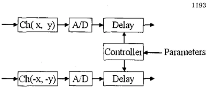
Fig. 2 shows the block diagram of a dynamic focus con- trol scheme. In this case, the steering term and @ are sent t o the delay controller for channels at (z, y) and (-z, -y)
Controller
Paraiieters
0-
.(+Ch(-x.
- y ) M N D
Delay
Fig. 2. A block diagram of the beamformer.
at the beginning of each beam. Based on the two param- eters, the controller then calculates the overall delay a t each range. Such a delay control scheme is very general and can be extended t o a broad range of beamformer ar- chitectures. For example, if real-time baseband interpola- tion is used, the overall delay can be further converted into a course time delay and a fine phase delay without chang- ing the basic structure of the proposed scheme. Based on the basic control structure shown in Fig. 2, the goal of the proposed method is to simplify the delay controller by ap- proximating the term @. The steering term is unaffected in the proposed method.
Another important feature of dynamic focusing in array imaging is the use of a constant flnumber to control aper- ture growth as the range increases. At sinall ranges, only channels close to the beam origin are used. As the range increases, more channels become active until the array is fully open. Therefore, the @ value related to the outside channels (Le., large (z, y)'s) may tolerate bigger errors as they are associated with a larger R. As will be shown later, this characteristic is also critical in developing the dynamic focus control scheme described in the next section.
111. THE DYNAMIC FOCUS CONTROL SCHEME There are three main components of the proposed dy- namic focus control scheme.
A. Grouping of Adjacent Channels
The first component is grouping of adjacent channels. In other words, the array is divided into segments (i.e., sub-arrays), and the same @ value is used by all of the channels in the same segment. Thus, the true value of @
is approximated by another value @' and
@'=@+6 ( 5 )
where 6 is the approximation error. Consequently, the total delay becomes
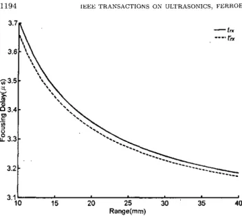
where t,, is the original delay and tk, is the approximated delay. The second term in (6) is viewed as a range focusing error, which may cause image quality degradation. Fig. 3
1194 3.7
[EEL: 'TRANSACTIONS OX ULTRASONICS, FERROELECTRICS. AND FREQUENCY CONSROL, VOL. 40, NO. !I, SEPrEh1RF.R 2002 In addition to the correction factor G, cadi ring is also partitioncrl into smaller segments to further reducc tlie er- rors at off-ccnter hearns. The radial length of each scgnient is determined based on 17). The annle E of each segment.
-
1"r , 3.6
\ , - .
on tlic other hand, can be determined by 533.5
'.
3.1 10
2
15 20 Range(") 25 40Fig. 3. Quantization error of thc range focusing term decreascs a5 a
function of range.
shows a typical example oft:, and t,,, wlierc tlic delay er- ror 6 corresponds to onc of the typical imaging conditions, arid the delay curves are shown for the rangc from 10 to 40 nnn. As expected, the delay error decreases as the range
R increases. Consequently, the image qualit,y degradation occiirs only at smaller rangcs, and the error is negligible when the range is sufficiently large.
Determination of the sub-array geometry is critical i n niininiizing tlie focusing error. The proposcd scheme devel- ops the geometry at zero.stcering angles (i.e., ct =
p
= 0") and then applies t,he result to all heams. According to (4),@ = '2
+
7~' when a =B
= 0'. Thus, a constant @ cor- responds to a circlc on the aperture wit,li the array center being the origin. It becomes obvious to divide thc arrity into concentric rings, and channels on the same ring can share the same @. To reduce potential approxirnation cr- rors for off-center beams, each ring is further divided irit,o smaller segments. Following this approach and derivatioii ont,lined in Appendix I3; tlic length An, of a particular ring along the radial direction is determined byAn
5
d ( n - 0.5)'+
16(n - 0.5)€1G X f/numher- (7L - 0.5) (7)
where n is the inner radius of the ring, E I is a pre- determined maximum delay crror normalized to tlic wave- length, and G is
: ..
correction factor defined as
where no is the radius of the first (smallest) ring and 7 is an adjustable parameter. In general, G can bc any mono- tonically increasing function of n/no. The purpose of G is
to inexease the length of outer rings further, as they are active only at larger ranges. Note that both n and An are defined i n ternis of number of array clcnients assuming half-wavelength pitch is used.
(9)
M x An
< = -
n
where M is a pre-specified aspcct ratio. Through this pro- cerliire, array partition can be implemented. Channels in- side the same segment iise the same @' value and, thiis,
share the same delay controllcr.
a'
can be defined as the mean of all @ valucs within the same scgment. The various parameters used in this discussion are graphically defined in Fig. 4(a), and a typical segmentation pattern is shown in Fig. 4(h). Let €1 = 0.05 (i.e., the maximiiini dclay error is 1/20 of tlie wavelength), 710 = 4, y = 0.15; M = 3, andflnumhcr = 2 , the 64-by-64 array (totally 4096 channels) can be coritrollcd by using only 227 controllers. Note that the total iinmber of segments is 454, and the 50% rednc-
tion is due to the even symmctry of @. These parameters will be uscd in subsequent simulations.
B. Quantization of @
For an N-channel array wit,li a half wavelength pitch aiid 145' maximum steering angles in azimuth, the n u n - ber of beanis is
&iV?
assiirnirig Nyquist heani spacing (Le.:A N
= (sin (45") - sin (-45')) / b s , where bs is the Nyquist hearn spacing defined as bs = (wavelength/2 . aperturesize) = l/N). For an N-by-N array with 145" rna,xinimn st,cering angles in both ru and0,
the numbcr of bcams beconies 2". Consequently. needs to bc speci- ficd for 2N4 (i.e.: N 2 channels t,imes 2 N 2 beams) different combinations. The purpose here is to develop a quantiza- tion schcnie for @ siicli that optimal focusing performance is maintained while minimizing the total nmnber of qnan- tization levels. Note that such a scheme cini reduce t,hememory requireiiient of the controller. Howcvcr, the over- all control bandwidth is still not affected.
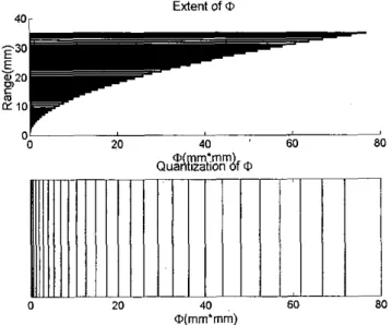
One example is shown in Fig. 5(a), where the horizontal axis shows extent of @, and the vertical axis is the range. Because of tlie f/num,t,er aperturc growth control, cxtcnt of
Q changes with range, as the outside channels do not be-
come active until a larger range is reached. Thus, a smaller quantization step is required when @ is small, and larger quantization errors may bc accepted when @ is large. In other words, nomimiform quant,ization of @ can be implc- mented.
Following the details described in Appendix C: the num- ber of quantization levels L can be obtained as
(10)
N
L =B f i x E 2 x f/nonrber
LI AND HUAKG: FOCIJS CONTROL FOR 3 - D I U A C I N G f; z 40 r Extent of 01 ~~
* .
" 0FIG.
4(a)FIG. 4(b)
Fig: 4. a) Definition of parametcis; b) a ssgincntation patlern of a
t w d i m s n s i o n a l array.
quantized value of @.at level i is
x
f,numbci)z Q i = 8x
(€2 xx ( 2 2 2 - 22
+
1) i E [l, L ] (11)where X is the wavclength a t the carrier frcquency. If a
uniform quantizcr is used in t,lie same situation, approxi-
mately L2 levels need tu be used to obtain the same level of accuracy.
An example of thc non-uniform quantization .is shown., in,. Fig. 5(h). Let N = 64, € 2 = 0.1, carrier fre-' quency = 4 MHz, and ,flnumber = 2, there are only 28 quan- tization levels. Among tlicse? t h e 28th quantizatiom- level is never used if the grouping scheme shown in Fig. 4(b) is used. Therefore, only 27 levels are required in this case.
C. Range Offset
Given a @', a fixed error is present at all ranges. The er-
0 20 40 ' 60 80
0 m*mm Quatkzzation
di
010 ..
O(mm'mm)
Fig. 5. a) Extcnt of 0 (horizontal) BS a function of R (vertical):
b) nun-uniform quantization of 0. At larger a's, cuaser quantization steps can be used.
Define t:z as the following
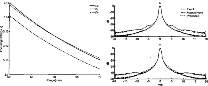
where Ro is the depth wit,h no focusing error. Cornpared with tlrc unconipeiisatcd approxinmtion, the focusing error beconics q times the original error at range
R,
where q is defined asBy properly select,ing Ro, q can he less than 1 a t all ranges. The effcct of range offset 011 thc range-dependent focusing
tcrm is illustrated in Fig. 6 with Ro = 60 mni.
IV. SIMULATION RESULTS
Simulations based on the angular spectrum rnebhod were performed t o investigate the cfficacy of the proposed approach. The angular spectrum method simulates wave propagation in thc spatial frequency doniain [SO]. First, t,he initial sound field is transformed to the spatial fre- quency domain via two-dimensional Fouricr t,ransform. Wave propagation is simulated by multiplying spatial spec- trum of the sound field with the following transfer function
(14)
j k A z d m
H
(fz,
f,:
Az)
= ewhere fz and
f,
are the spatial frequencies corresporid-ins to x and
u.
resnectivelv;.
" . Az is the nropaaation.
dis-1196 IEEE TRANSACTIONS ON ULTRASONICS, FERROEl -..,
-.
..
-.
I
3.1 50 55 60 65 70 Range(")Fig. 6. The offset compensation technique; 60 mm is the range with
no focusing error.
dimensional inverse Fourier transform is then taken to o b tain the sound field at the new depth. Such a process can be repeated over all frequency components for pulse wave propagation. The pulse wave sound field can be obtained by summing results at all frequencies of interest.
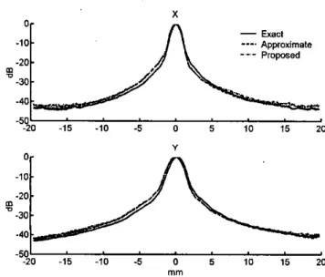
Simulated beam patterns a t several steering angles and ranges are demonstrated from Fig. 7 to 10. Only one-way receive beam patterns are shown. The corresponding two- way response can be obtained by multiplying the fixed focus transmit beam with the dynamic focus receive beam. A 4-MHz, 64-by-64 two-dimensional array was assumed. Each figure shows the projection of the beam plots along the x (upper) and the y (lower) directions. In each figure, the solid line represents beamforming results using ideal delay values (Le., no Fresnel approximation). The dashed line shows the results based on the approximated delay values described in ( 6 ) . The results of the proposed method
are shown by the dot-dashed line. A depth of 60 mm was
used to offset the focusing error (i.e., Ra = 60 mm). Fig. 7 demonstrates the beam plots for cy = O",
p
= O", and R = 15 mm. It is shown that a t 15 mm, sidelobes are slightly elevated from the ideal case because of delay ap- proximation. Nonetheless, the sidelobes are mainly underthe -30 dB level, and the mainlobe width is unchanged. Such errors decreased as the range increased t o 30 mm. The three beam patterns for LY = O n ,
p
= O", R = 30 mm are shown in Fig. 8. In this case, the three beam pat- terns are almost identical. Simulated sound fields a t non- zero steering angles are demonstrated in Figs. 9 and 10. Fig. 9 shows the beam patterns for cy = Zoo,p
= 40",R = 15 mm, and Fig. 10 shows the beam patterns for cy =
20",
= 40",R
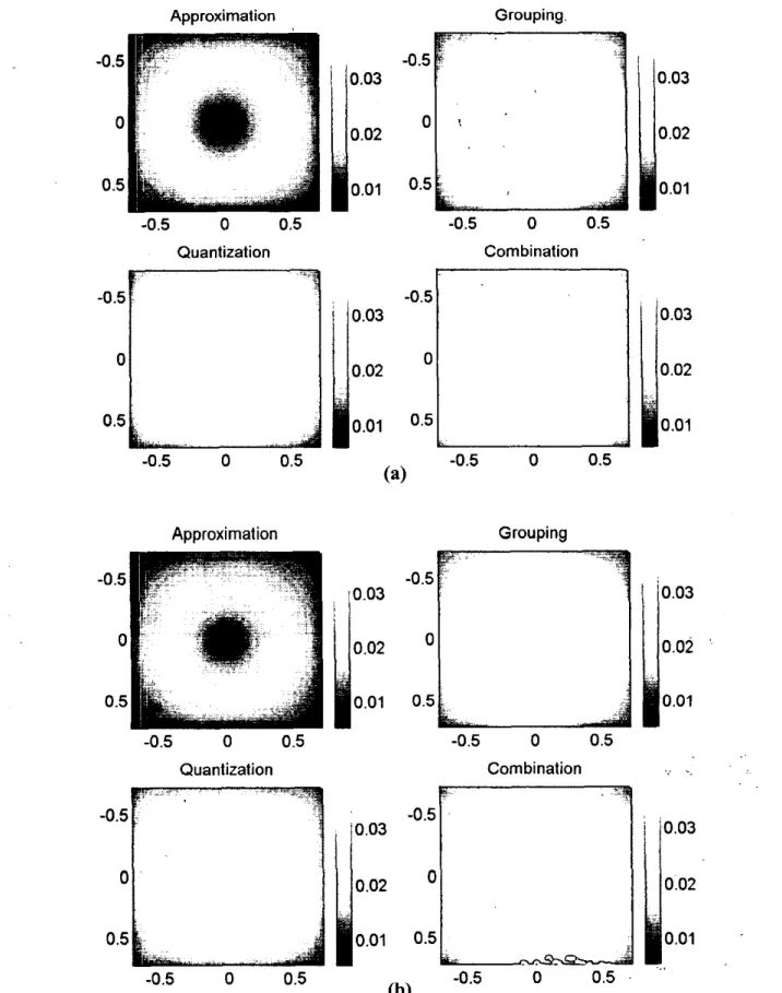
= 30 mm. In this case, slight steering errors are prescnt.Mean and standard deviation of delay errors as a func- tion of steering angles are shown in Fig. 11
( R
= 15 mm)and Fig. 12 ( R = 45 mm), respectively. The delay er-
rors are normalized t o the wavelength at the center fre-
.ECTRICS, AND FREQUENCY CONTROL, VOL. 49, NO. 9, SEPTEMBER 2002 X
-
Exad ---. Approximate Y 0 -10 -20 -30 -40 5 0I
-20 -15 -10 -5 0 5 i o 15 20 "Fig. 7. Simulation results at 4 MHz. a = Om, 4 = O O , R = 15 mm. Projections of the three methods in x (upper) and (lower).
X 0- -10
-
Approximafe -20. -30. -40 -50---
proposed m-
-20 -15 -10 -5 0 5 10 15 20 Y -5 $0 4 5 .io-6
06
rb
I;
io
mmFig. 8. Simulation results at 4 MHz. a = 0°, fl = Oo, R = 30 mm. The format is the same 85 that in Fig. 7.
quency. At each range, the statistics are calculated from all channels given an ( a ,
p)
combination. In each panel, the horizontal axis indicates sin(a), and the vertical axis indicates sin(p). The mean values are shown in Fig. l l ( a ) , and the standard deviation values are shown in Fig. l l ( h ) . In each figure, the four images are for the Fkesnel approx- imation (upper left), grouping of adjacent channels ( u p per right), non-uniform quantization (lower left), and the combination of both approaches (lower right). The results forR
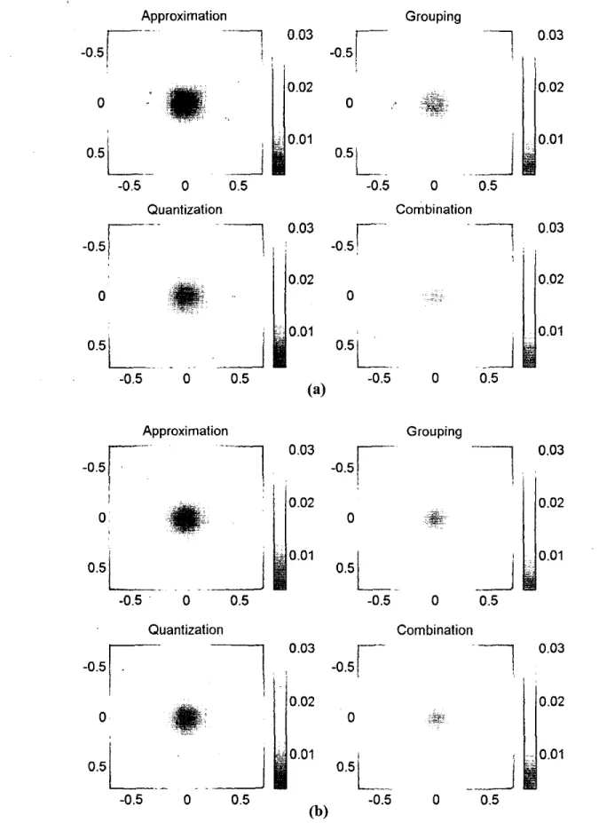
= 45 mm are shown in Fig. 12. As expected, both the mean and standard deviation of the focusing errors decrease when the range moves from 15 to 45 mm. At 60 mm, the errors are at the smallest because of the range offset. The mean and standard deviation then gradually increase after 60 mm. Note that at 15 mm, the apertureLI AND HUANG: FOCUS CONTROL FOR 3-0 IMAGING
- l j j ,
-20 Approximate -30 -40 -50B
a '.,.-, --_... I-..-. -20 -15 -10 -5 0 5 10 15 20"
-501 -20 -15 -10 -5 0 5 10 15 20 mmFig. 9. Simulation results a t 4 MHz. a = ZOO, 0 = 40°, R = 15 mm.
The format is the same as that in Fig. 7.
X 0
-
Exact- - -
P r o w e d -10 Approximate -20 -30 -40 B 5 10 15 20 Y -20 -15 -10 -5 0 5 10 15 20 m mFig. 10. Simulation results a t 4 MHz. a = Z O O , The format is the same as that in Fig. 7.
= 40°, R = 30 mni.
is not fully open, thus making the errors resulting from Fresnel approximation relatively small. Also note that a mean error of 0.02 wavelength is equivalent to uniform de- lay quantization with a step size of 0.04 wavelength (i.e., mean phase error is 21r/25). The errors can be reduced by employing smaller quantization steps.
V. DISCUSSION AND CONCLUDING REMARKS
The proposed control scheme only requires two parame- ters (i.e., the steering term and
a)
at the beginning of each beam. The 1/R term can be implemented by using a single bit control signal. Such a control signal is generally 0 unless an additional delay is required. The memory requirement of such a single-bit control scheme is around 34 Kbits as-1197
suming 128-MHz delay resolution and a 20-cm imaging depth. Thus: the 27 single-bit control signals used in the simulations can bc stored in less than a 1-Mhit memory (27 x 34 Kbits). Note that the 128-MHz clock rate is used
as an example. In practice, the delay update rate does riot need to be as high as the sampling frequency. In this case, the complexity can be further reduced. Fig. 13 shows a
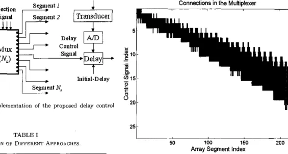
possible architecture to take advantage of the given control scheme, where focusing patterns are stored in the control signal table, and multiplexers are used to replace complex delay controllers. It must be noted that the reduced mem- ory requirement caused by non-uniform quantization does not reduce the overall control bandwidth. In addition, the scheme shown in Fig. 13 may hc implemented as a central- ized controller (i.e., a single multiplexer) or a distributed controller (i.e., niultiple multiplexers), depending on the control bandwidth requirement of the imaging system.
Comparisons of the conventional architecture and the proposed architecture are listed in Table I. For a 64-by- 64 two-dimensional array, there are 4096 channels. The conventional architecture may exploit the delay symme- try and uses 2048 controllers. In addition, each delay con- troller may or may not require a complex algorithm to compute the delay changes in real time. Through g r o u p ing of adjacent channels, the number of controllers is re- duced to 227. Also, each controller requires otily a srnall table and a multiplexer. The size of the multiplexer can be further reduced. As shown in Fig. 14, not all of the con- nections between selection signals and delay control signals are needed. As shown in Fig. 14, only 20% of the total pos- sible connections are required. Thus, further reductioii of
the multiplexer size is possible. Because of the significant reduction in the number of focus controllers and the n u n - her of quantization steps, the multiplexer architecture in combination with the single-bit control scheme beconics a realistic and effective focus control scheme. Again, such a
scheme may be used a s a centralized controller or a dis- tributed controller, depending on the control bandwidth requirement.
The method simplifies control of the focusing delay, but the steering term in (3) is still needed. For 4096 channels and 8192 beams, there are t,otally 32 M words of initial delays. The word length in this case is determined by the extent of the steering term and the desired focusing accu- racy. The 227 segments for the range focusing term require a memory space of 1.8 M words. Because the two param- eters are only needed at the beginning of a beam, and dynamic range updat,e is riot required, data communica- tion requirements are manageable with current technolo- gies. Alternatively, t~lie approach proposed in [19] for the steering component can be used.
The methods can also be applied to one-dimensional arrays. Because the total number of channels for a one- dimensional array is not as large, grouping of the adjacent channels may not be necessary. Nonetheless, non-uniform quantization can still be employed. To avoid image qnal- ity degradation in the near field, more quantization levels can be used. In other words, the delay error can be easily
1198 IEEE TRANSACTIOXS ON ULTRASONICS. FERROBI.ECTRICS, AKD FREQUENCY CONTROL, VOL. 49, NO. 9, s E P 1 ” L B m 2002 Approximation . . Grouping.
-0.5
0.03
0.020
0.5
0.01-0.5
0
0.5
-0.5
0
0.5
Quantization Combination-0.5
-0.5
0.03
0.03
0.02
0
0.02
0
0.5
0.01
0.5
0.01
(4
-0.5
0
0.5
-0.5
0
0.5
Approximat ion
Grouping-0.5
0.03
0
0.02
0.5
0.01
-0.5
0
0.5
-0.5
0
0.5
Quantization Combination-0.5
0.03
0
0.02
0.5
0.01-0.5
0
0.5
-0.5
0
0.5
(b)
Fig. 11. Mean (a) and standard deviation (b) of focusing errors as a function of steering angles at 15 mm. Results from the Fresnel approximation (upper left), grouping of adjacent channels (upper right), non-uniform quantization (lower left), and combination of both approachcs (lower right) are shown.
LL AND H I I A NC: POCUS COWL'KOL FOR 3-0 IblAGlXG 1199 Approximation Grouping
I--
-__?
0.03
1 ,-0.5
I 0.02-0.5
r--
0
0
0.010.51
i.
~~-0.5
0
0.5
O L.A
0.5
-0.5
0
Quantization Combination-0.5
I---
-0.5
r
-7
,0.03
0.5/
0.020
0
0.01-0.5
0
0.5
0
0.5
(a)
0.5i..
-0.5
. . . .-
Approximation Grouping-0.5
'0
0.5
-0.5
0
0.5
Quantization Combination-l
0.03 0.02 0.01 _.A
0.51
'j
-0.5
0
0.5
0
0.5
Fig. 12. Mcaii (a) and standard deviation (b) of focusing errors ai a function of steering angles a t 45 mrn. Results from .the Fresnel approximation (upper left)l grouping uf adjacent clrarineis (upper rigtit); non-uniform qnantizat,ion (lower left), arid combinat,ioir of both approaches (lower right) are shown.
1200 IEEE TRANSACTlONS ON ULTRASONICS, FERROELECTRICS, AND FREQUENCY CONTROL, VOL. 49, NO. 9, SEPTEMBER 2002 TABLE I Control Signal Table
1
COIltrOl- l L
Initial-Delay N,Fig. 13. A possible implementation of the proposed delay control
scheme.
Connections in the Multiplexer
Original Proposed
Fig. 14. Connections in the multiplexer. The array segment index is arranged from the array center to outer segments. It is shown that Number of controllers 2048 227
Image quality Excellent Slight degradation not all possible connections are needed. Steering table 32 M words 32 M words
Control signal table None < I Mb
at shallow depths
Table 16 M words 1.8 M words and
0' =
( f d -
2 f p z z+
z')+
( f p i - 2 f p v y+ Y') +
f p : 2RP
-
- R2 + r 2
+
y2 - - ( s t a n a+
y t a n p ) . ('45) reduced to be less than that generated by a sampler work-ing at 32 times of the carrier frequency. In this case, the If R satisfies the following condition overall architecture is still simpler than the conventional
approaches.
R
'
>>
(zz+
y') .then the distance D can be represented as
(" + )Y' ~
2
( r t a n a+
y tan@) (-47)2R2 RP
1
( r 2 t a n 2 ~ + ~ 2 t a n 2 ~ + 2 z y t a n c u t a n ~ )
i
Define the plane t = 0 as the aperture plane. Assume
that the distance between the channel ( 2 ; y) (i.e., with three-dimensional Cartesian coordinate (x, y, 0)) and the the array center (Le., (0, 0, 0)) and the focal point is R; the following equations can be derived based on the notations defined in Fig. 1.
Y R 1
+
focal point (fp., f p y , f p , ) is D , and the distance between 1 4
8 " -
- _
z tan a+
y t a n b P(2
+
y')+
(z
tan0
- y t a n a ) ' 2RP' = R -+
0' = ( f P z-
R'
= fp;+
f p i+
fd
f p , = f p , x t a n a f p , = f p zx
t a n @+
UP,
- Y)2+
fPZ The receive delay of channel (z, y) relative t o array cen- ter is D - R t,, = ~ c ('41) (A21 z t a n a+
y t a n p cJ1+ tan' a+
t a n 2 p(2
+
y')+
( x t a n @ - ytancu)'-
_ -
(A8) R' = f p : x ( 1 + t a n 2 a + t a n 2 p ) .1
Define P as + 2Rc(l+ tan2 a+
tan'0)
'Thus, the range dependent focusing parameter defined as
can be
p 1
+
tan' a+
tan2@, (A31then f p , can be rewritten as
R
f P z =
p
('44) ' (A91( ~ ~ + y ~ ) + ( x t a n f l - y t a n a ) ~ (1
+
tan' a+
tan20)
LI AND HUANG: FOCUS C O N T R O L F O R 3 - D IMAGING 1201
APPENDIX B
t
w
I
- - + a ) Letting T represent the distance between channel (z, y )
-
o
at
a)' a)- Ln*mand the array center ii.e.. ~. T' =
'
x
+
v21,
we have theI I .
following equation for the center beam (Le., a =
0
= 0"): ~ i15. ~ if^^^ quantization of . a.The function G is used to increase the length of outer rings further, as they are active only at larger ranges. It can be any function that monotonically increases with n/no.
In this Paper> it is defined as (B1)
@ ( r ) ) = T 2
.=p=o"
The parauleter can also be viewed as the radius of a ring on the aperture with the array center being the ori. gin. Grouping of adjacent channels is done by dividing the aperture into several concentric rings, and then each ring The radius T of each ring is determined based on uni-
is further partitioned into smaller segments.
G
= exp [T(E
~ I)] (B10)Finally, each ring is further partitioned into smaller seg- ments. The angular span of each segment can be defined as
a=pL1=O-
6s
= [@(T+
AT) - @ ( T ) ]I
= ( r
+
AT)' - T*= % ( A T ) - (AT)'
<=-
M x A n nLet €1 be the desired maximum quantization error normal-
ized t o the wavelength A, the following inequality can be
obtained: in Fig. 4(a).
where &I is an aspect ratio of the segment. Definitions of
the parameters used in this appendix are also illustrated
where the factor of 2 converts the maximum focusinn error
-
APPENDIX CAt zero steering anglcs, the maximum value of is to an equivalent quantization interval. G is a correction
term that will be defined later. Since flnumber = R/2r, we have
6s
5
8761XG x flnumber. (B4)After some arrangements, the following equations can be obtained
and
AT
5
T*+
~ T E I X G x flnumbcr - T . (B6) Given the pitch of the array, (B6) can also be repre- sented in terms of the number of channels. For onehalf wavelength, fully sampled arrays, we haver =
(n
-
0.5) x pitch 037)and
AT = An x pitch. (B8) Hence, the radial length of each ring in terms of the num- ber of channels becomes
An 5 d ( n - 0.5)'
+
16(n ~ 0.5)e1G x flnumber- ( n - 0.5). (BS)
amax
= V i a x (C1) where rmax is the largest radius on the array. For an N - by-N array,(C2) N
rmax = - x pitch.
The purpose of non-uniform quantization is to determine the number of quantization levels L and the quantization interval for each level between 0 and
amax
given a pre- specified maximum quantization error. The design strategy can be illustrated using the one-dimensional plot shown in Fig. 15. Let the quantization interval at a radius T be 26(r), we haveJz
60
= E 2 X2R
where X is the wavelength at the carrier frequency, and E? is the pre-specified maximum focusing error normalized to the wavelength. Because flnUmber = R / 2 r , we have
6 ( T ) = ~ E z X T x flnumber. (C4)
1202 IEEE TRANSACTKISS DE ULTRASONICS~ FERROELECTRICS, AND FREQUENCY C ~ I N T H O L . ~ O L . 49, NO. 9, SEPTEMBER 20W
then
Thus
The nilrriber of levels hecoines
[9] W. E. Engeler. M. O'Donnell, J .
'r.
Pedicone, and J. J . Bloomer; "Dynamic phasc focus for colicrent imaging beam for- matiun.'' U.S. Patent 5 111 695. 1Y02.[IO] hl. 1.1. Bac, "Focusing delay calculation method for real-timc digital focusing and apparatus adopting the same," U.S. Patent 5 836 881, 1998.
[Ill R . A. Beaudin and Ril. P. Anthony, "Delay generator for phased array ultrilsound beamformer," US. Paient 5 622 391, 1996.
[I21 D. H. Turnboll and F. S. Foster, "Beam steering with pulsed tww diiriensional transducer arrays," IEEE P a n s . Ultmson., Feme- 1131 C. hl. W. Daft, L. S. Smith, and M. O'Donnell, "Beam pr"
files and images from twwdimensional arrays," i n Pmc. I E E E Ultmson. Sump., pp. 775-779> 1990.
1141 S. W. Smith, G . E . Trahcy, mid 0. T. von Ramm, "Tw- dirnensional arrays for medical ultrasound," Ultrason. h a y . , "01. 14, no. 4, pp. 213-233, 1992.
[ls] P.-C. Li and h1. O'Donneli, "Phase aberration correctiou on t w h dimensional conformal arrays: IEEE Tram. Ultmson., Ferro-
elect., Freq. Contr., "01. 42; no. 1, pp. 73-82, 1995.
1161 E. D. Light, R. E. Dauidsen, .I. 0. Fiering, T. A. Hruschka, arid S. W. Smith, "Progress in two dimensional arrays for real time volumetric imaging," Ultrason. Imag., vol. 20; no. 1: pp. 1-16,
F W ~ . Cdntr., VOI. 38, no. 4, pp. 320-
1998.
[17] P. K. Weber, R. M. Schmitt, 5. I). Tylkowski, irnd .I. Steck, "Optimiaat,ion of random sparse 2-d transducer arrays for C3-d clcctronic beam stecririg and focusing," in Proe. IEEE Ultmson.
S y r n p P , pp. 1503-1506, 1894.
1181 S. S. Brunke and G. R . Lockwood, "Broad-bandwidth radiation patterns of sparse twc-dimensional vernier arrays," I E E E 7 h n . s .
Ultmson., Fewoelect., Freq. Contr., vol. 44, no. 5, pp. 1101-1109, [IY] B. J . Sword. "Beamforming methods and apparatus for threc-
..
-
-
8 4 E 2 X f / n u m b e r '
Each eniry in the @ table caii then hc expressed as
i-1
@I = 1 2 6 1
+
6,
= 4E2X(z
+
T i ) x f j n u m b e r .I = i 1997.
(")
diniensional ultrawnnd imaging rising twhdimensional trans-
ducer array,"
u.s.
pate,,t[20] D. L. Liu and R. C. \Vag, "Propagation and hackpropagai.ion for ultrasonic wavefront desian." IEEE Trans. Ultrason.. F e m -
Aft,er sonie arrangements, t,he following representation caii 013 032, 2000,
be ohtaincd:
I
@; = 8 (€*A x flnllmber) 2 x ( 2 i 2
-
2 i+
1) elect., Fieq. Contr., VOI. 44, no. 1, pp. 1-12, lYY7( C W
Pai-Chi Li iS'91-bl'93-S'93~h~'s5-SM'Ol) received the B.S. degree in electrical engineer-
ing from National Taiwan University, Taipei,
T&iwan, R.O.C. in 1987 arid the M.S. and
Ph.D. degrees from the University of htichi-
ACKNOWLEDGMENTS
The authors tllank M.-L. Li for the assistance in pro-
gan, Ann Arbor in 1990 and 19941 respcc- tively, both in electrical engineering: systems. Hc was a research assistant with the De- partment of Electrical Engineering and Com- putcr Science from 1990 t u 1904. He joined Acuson Corporation (Mountain View, CA) as a member of thc Technical Staff in June 19!14.
dacing some of the figures. They also thank tlic reviewers for helpful comments.
REFERENCES
K. E. Thomenilis, "Evolution of ultrasxwitl hexmformers," in Pm~c. I E E E Ultmson. Symp., pp. 1615-1622, 1996.
S. H.,,klaslak and H. G. Larscn, "Dynamically focused linear phaqed array acoustic imaging system," U.S. Patent 4 699 009, 1985.
D. Lipschuta, "Delay interpolation for digital phased array ul- trwound beamformers:" U.S. Patent 5 345 426, 1994.
W. E. Engeler and C. M. W. Daft; "Ultrzsonic imaging having widehandwidth dynamic focusing," U.S. Patent 5 488 588,1996. M. O'Dormell, W. E. Engeler, J. J. Bloorncr, and J. T. Pedicone, "Method and apparatus for digital phaied array imaging," U.S. Patent 4 983 970: 1991:
K . Jeon, M. H. Bae: S. B. Park, and S. D. Kim, "An cfficient real time focusing delay calculation in iiltrwonic imaging sys- tem:" Ultnuon. I7nag.; vol. 16: no. 4; pp. 23-248, 1994.
S. R . Freeman,, bl. K . Qnick: hl. A. h,lorinl R. C. Anderson, C. S. Desilets, T. E. Linnenbrink, and RI. O'Donnell, "Delta- Sigma c.versampled ultrasorind ijeaniformer with dynamic dc- liifs," I E E E Tmns. Ultmron.; Fewoelect., Freq. Cmtr-., vol. 46,
no. 2, pp. 32&332, 1999.
A. Geel C. R. Colel and J . N. Wright, "Method and apparatus for
focus control of transmit and recciw bcamfurrner systems," U S Patent 5 581 517, 1996.
His work in Acuson was primarily in the areas of medical ultra- sonic imaging system design for hoth cardiology and general intag- ing applications. In August 1 9 9 i , he wcnt hack to thc Departrncirt
of Electrical Engineering a t National Taiwan University w Assistant Professor. He then became Associate Professor i n August 1998. His currcnt research interests irrcliide biomedical ultrasonic imaging and signal processing.
Dr. Li is a member of IEEE, and he was the recipient of tire Distin- guished Achicvement Award in Electricill Engineering: Systems fur his outstanding academic achievement a t the University of Michigan.
Jine-Jumz Huane was born in 1976 in Tai- wan: R . 0 5 . Hc &ved the B.S. and A1.S.
degrees i n electrical engineering from National Taiwaii Univcrai~y in 1999 and 2001: respec-
tively. His research intcrest is ultrasonic imag- mg system dcsign.