Abstract
In this paper, a prototype of a non-conventional electro-magnetic actuator (EMA) is proposed. It is a repulsive magnetic system consisting of a motion pad and two active coils. The movement of the motion pad is due to the repelling force between the coils and the magnets affixed to the pad. First, the dynamic model is derived and analyzed. Next, an adaptive controller is developed to deal with the unknown parameters with the objective of precision positioning in this system. From the experimental results, satisfactory performances including regulation accuracy and large-moving range have been demonstrated. This implies the excellent performance is possible to achieve by just using an advanced controller rather than a costly hardware setup. Keywords: Electro-magnetic actuator, Permanent magnet,
Adaptive sliding mode control, Precision positioning.
1. Introduction
With the progress of the industrial technologies, high-precision positioning plays a more and more important role in a variety of high-tech applications, such as IC-photolithography (stepper and repeated positioning), material science (tunneling microscopy), medicine and biology (research of cell biology). To meet these challenging needs, more stringent manufacturing processes and advanced fabrication equipments, therefore, should be developed. Recently, for a small range motion, flexure systems seem to be able to satisfy many positioning requirements. An example is a piezoelectric actuator[ 1][2] which can realize lOnm resolution with 1pm travel. On the other hand, large-moving range precision motion, such as the steppers in IC-lithography, is based on devices with ball-screws or linear motors[3][4]. However, in traditional mechanical actuators, mostly the piezoelectric actuators only handle the small moving range, the ball-screws cause
Design, Analysis and Control of an Electro-Magnetic Actuator
Mei-Yung Chen', Tzuo-Bo Lin', Shin-Guang Huang'
and
Li-Chen
FuIF2
I
.Department of Electrical Engineering2.Department of Computer Science and Information Engineering National Taiwan University, Taipei, Taiwan, Republic of China.
0-7803-7896-2/03/$17.00 02003 IEEE
disturbances and backlash due to roughness of the bearing elements, and the linear motors have ripple effect in a motion stroke.
These reasons motivate us to design a new electro- magnetic actuator to achieve the objective of large-moving range and high-precision positioning. It is a repulsive magnetic system with a passive motion pad and two active coils. The motion of the pad results from the repelling force between the magnets affixed to the pad and the coils on the linear guide. The dual coils is devised to increase stiffness of this system.
In this paper, we build an EMA, whichself is a positioning system. Then, a dynamic model will first be derived, and based on this model an adaptive controller is
designed to deal with unknown system parameters so as to achieve satisfactory system performance. To demonstrate the effectiveness of the entire system design, experimental results are provided for verification.
2. Prototype of Electro-Magnetic Actuator
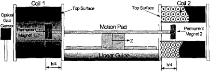
Figure 1 shows the structure of the prototype of EMA.In this section, we organize the content as the presentation of a sequential design concept instead of a lengthy detailed description. Some necessary discussion on part of the design concepts will be given. Subsequently, the illustration about the materials that we used, and the resulting geometric shapes, will be conducted in the end.
Figure 1 : Perspective of whole electro-magnetic actuator.
This research constructs the motion pad embedded with two magnets, as illustrated in Fig. 1 which demonstrates various views of the entire mechanism. To keep lightweight of the pad and to prevent it from being magnetized, the pad is made of aluminum. About the magnets, in our previous research[5], the material NdFeB seems to be the best choice of materials for the magnetic levitator at present, since AlNiCos has low coercivity, Ferrites has low remanence, and Samarium magnets are still quite expensive. There are several useful characteristics of the material NdFeB, including that the remanence is 1.29T, the coercivity is 990kA/m, the resistivity is 1.5 ,LL (;1 m, and the maximum energy product is 320kJ/m3. In this paper, the diameter of NdFeB magnet is 30mm and its thickness is 3mm. The total length of the pad is 100mm, and its mass is equal to 8Og.
In general, the relationship between the magnetic flux density B and the magnetic field intensity H in a free space can be defined as:
&,I) = ,UoH(z,I)
,
(1)where po denoting the permeability in a free space is equal to 4 7c ~ l o - ~ H / m . Without the presence of electrical field, the expression of the Lorentz force[6] for an infinitesimal current loop can be simplified as
F ( z , l ) = (m . V ) B ( z , l )
7 (2)
where m is the dipole moment of this infinitesimal current loop.
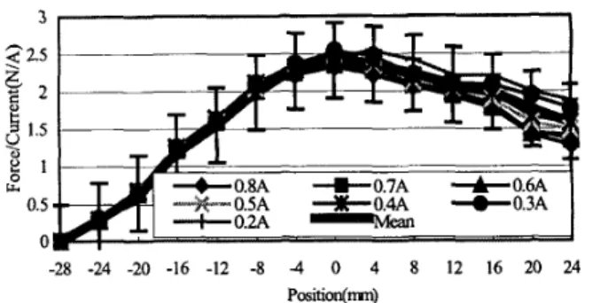
However, it is difficult to establish a compact analytical model of the magnetic force from the former derivation. Thus, our alternative is to derive the empirical model based on actual measurements of the relationship of F(z,f) against the current I and the position z as shown in Fig. 2, where we set z=O at the top surface of coil and let the total measuring range z~[-28mm, 24mml stem from the center through the top surface to the outside of the coil.
3. System
Modeling
In the previous sections, the mechanism design of an EMA has been described. Its analytical model will be derived and analyzed in this section,
Before we proceed with the modeling, several assumptions are necessary in order to make the problem
3 < 2.5 h 6 2
2
1.5.
8 1 U. 0.5 0 -28 -24 -20 -16 -12 -8 -4 0 4 8 12 16 20 24 Position(m)Figure 2: The relation between F(z,O, current
Z,
and positionL.
more tractable.
A. The N-turn wires of the coils distributed across their cross sections can be viewed as lumped a single wire located at their cross-geometric centers. This allows one to closely approximate the exact forces in a more practical manner.
B. Each magnet is considered as one single magnetic dipole carrying the same magnetic dipole moment and is located at the center of each magnet.
C.
Based on the relation between the magnetic force vs. the desired current I, and position z, it can be foundthat the force/current ratio is approximately
proportional to position z at the range z~[-28mm, O m m ] inside the coil.
The motion pad is considered as a rigid body with the center of mass coincident with the center of geometry. The principle of linear momentum depicted by Fig. 1 leads to the following equations:
= ZU,
(a
+
Z) - IU,(a-
Z )+
Ffii’(3)
where A4 is the mass of the pad, F(z, Z,) and F(z, 12) denote the forces induced by the left and right stator electromagnetic circuit in the z position, respectively, Fs,~ represents the Coulomb friction of the linear guide, K is a constant relating the force and the driving current and h is the axial length of coil. Then, the dynamic equation (3) can be rearranged as:
Proceedings of the American Control Conference Denver, Colorado June 4-6, 2003
Kh 4
A&
= K(Z,+
Z,)Z +-(I, - Z,)+
Fri.
(4)4.Controller Design and Stability Analysis
In the previous section, based on several assumptions, the complete dynamic model is then derived. However, in practice there should exist some modeling errors. Therefore, the controller to be developed should sufficiently be robust to these system uncertainties and unmodeled dynamics. Besides these uncertainties, the controller also has to eliminate the effect due to disturbances. In this paper, we adopt an adaptive controller to fulfill the above needs.4.1
Controller
DesignIn order to simplify notations in the following derivations, the control inputs can be redefined as
( 5 )
Since we have two control variables u1 and u2 at hand for controller specification and one output variable to be driven to zero, we have choice to set ul as any constant. In other words, ul and u2 (hence I , and I,) are dependent
control variables. Thus, with ul being set as a constant and
u2 being set as shown earlier, we can completely specify the currents (ZlJ,). Then, by definition in Eq.(5), Eq.(4) can be rewritten into a state-space form as:
S = G , E
+
G,E , (8)where Go, G a O . In this application, we try to regulate state error E to zero, which simultaneously regulates the derivative of E to zero as well. Due to this reason, if the sliding surface tends to zero within finite time can be proved, then E and E are also forced to zero exponentially. To relate the sliding surface to the dynamics of motion, we find out the time derivative of the sliding surface is:
S
=G,E +G,E.
(9)As described in the previous section, an adaptive controller is applied in this research, which is capable of estimating parameters of the system on-line while controlling the system simultaneously. After we have the estimates of system parameters, Eq.(9) with these estimates in the control command can be used. So, we substitute the estimates acquired from the on-line estimator and derive the following:
U
=D,,G,-'(-LG,E-
LG,E-
G ~ E )where L>O, D E , D, , and
C
are the estimates of DB, DA, and v , respectively, and sat(.) is the saturation function defined as:I 1 S > E
M E = A E + B U +
w
, ( 6 )( - 1
s
< --Ewhere E=z is the error state variable and U=u2 is the control input. Note that the external friction and the high order terms left out from linearization are all aggregated into the term W. Apparently, A=K(I,+I,)=KC, and B=KhI4, and the system is a actually a nonlinear one.
Now, rewrite the Eq. (6)
D,E=
-
D,E+U+v , (7)where D,=ilClh, D8=4mlKh, and v=4 WIKh. However, due to lack of knowledge of the system parameters, we assume DA,
DB, and v are unknown beforehand. Then, assume a sliding surface variable S with the following form:
Thus, substituting Eq.( 10) into Eq.(7), we can obtain
D,[C,-'S
+
L(G,-'S)] = - 6 , E+
V+D,(-LG,-'S - G , - ' G p E )
-
s a t ( S ) , (12)where the estimation errors are defined as
D E = D ,
-
D , , D , = D,-
6 ,
and 6 = v - ;.
By applying appropriate gains L,GD
and Gp, we can accelerate the convergence and force them to zero in a shorter period of time.-
-4.2 Stability Analysis
Proceedings of the American Control Conference Denver, Colorado June 4-6. 2003
In the previous section, we have derived the close-loop function in Eq.(12), which involves estimation errors. Now, with the help of estimator based on adaptive control theory, we then can derive the estimates, so that appropriate control commands are also derived.
We define a Lyapunov function candidate V, which is a positive definite function:
where
r,-',
rz-'
andr3-'
are all positive values. First, the time derivative of the Lyapunov candidate function Vcan be found out as:
along the solution trajectory of S in Eq.(8). Then, it can be rearranged by means of Eq.(14) into the following:
DBr,-'(ijA) - ( f i A ) T D,(G;'S)E']
+ t r [ ( i j B ) T
D,r,-'(fi,)
+(OB)T
DE (G,-'S)(-LG,-'S-
G , - ' G , E ) T ] +tr[(C)TD,I'3-'(v")+
( G ) T D B ( G D - ' S ) ] .Now, we devise adaptive laws as follows:
hA
=-6"
= -I',(G,-'S)ET,bB
=-dB
= T,(G,-'S)(-LG,-'S -GD-'G,E)',t
=-6
= (G,-'S).
If these equations hold, Eq.( 15) will become V = -STG,-'D,TD,LG,-'S - STG,-'DBTD,G,-'sat(S) I 0
S 2 > (17)
-s~G,-'D,~D,LG,-'s - L- I
o
Is1
< E Ebecause Go-', DB and L are all positive diagonal matrices so
that they are commutable in deriving the inequality. And Eq.(17) also implies that the equilibrium D, =
d,
,D, =
6,
and v = C of the respective equations is uniformly bounded. Using arguments similar to Burbulutk Lemma[7] we establish that S E L ~ ,SE^,
the most important consequenceIs(t)l-+
o
as t+
CO.Due to zero convergence of S, it can be readily verified that E coverage to zero asymptotically. In other words, state variable and time derivative all converge to zero eventually, which is the goal of designing the controller for this system.
5.
Experimental Results
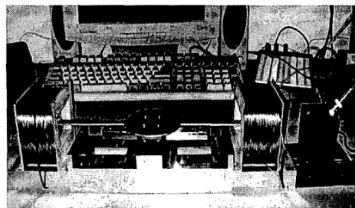
The experimental hardware, including the main body, sensor system, driver system and controller hardware, will be described here. Figure 3 shows photographs of the physical set-up. A number of experimental results, including the transient and the steady-state responses in different situations, will also be provided in this section to demonstrate the performance of this system with the controller presented in section 4. Based on these results, some important aspects of future research will be presented.
5.1. Experimental Hardware
Figure 3: Photograph of an aspect of the physical system.
This sensor device, which is chosen to be ILD 1400-50, and it is manufactured by the Micro-Optronic Technology, in Germany. Its rise time can be as low as 200psec whereas the active range is up to 5Omm(ROM) with a resolution of 0.1 %
of ROM, which means this sensor is fast enough and can cover all the traveling range in this application. The drivers type is CO-502-001Q Torque Amp. manufactured by CMC Inc. in USA. They are linear drivers designed to be servo drivers for DC motors. The power is 250Watts: 5 Amps for SOVolts. The current microcomputer is an IBM PC with Pentium microprocessor inside. The clock rate is 733MHz which allows this research to accomplish a real-time control implementation.
5.2. System performance
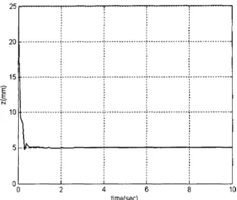
The control parameters for the adaptive controller are set as L=2.5, Gp=20, GD=4.7, and ~ = 0 . 0 0 1 5 . Figure 4 show the transient responses to the situation with the largest initial transitional displacement range, i.e., 25mm in this mechanical system. From the trajectories of state, one can see that the error signals converge to their steady states within about 1 second, Then, in Fig. 5 , the final precision is made up 5pm in translation which is estimated to reach a limit of the sensor device.
Figure 6 shows lmm step input control test. To explain the meaning of the result, it is necessary to consider the resolving capability of the measuring device firstly. Namely, the repeatable accuracy is about 5 p .
From the experimental process, adaptive controller, which can on-line perform system identification implicitly or explicitly while tuning the controller gains to guarantee the stability of the closed-loop system.
6.
Conclusion
In this paper, we designed a precision EMA for larger moving range. The dynamics of the EMA system have been thoroughly analyzed and then a complete model also has been derived. The system is treated as a multi-input signal-output system, and an adaptive controller has been designed here and implemented using a microcomputer. In the same time, the good performance can revealed that precision motion control is achieved.
Since the main objective of this work was to illustrate how an adaptive controller can be applied to EMA system. For the high-tech industrial technologies, the machine must be employed in a high-quality clean room or in a vacuum environment, for instant, semiconductor industry. In order to meet this requirement, we want to use the magnetic levitation techniques instead of linear guide in this EMA system. It is believed that more complex modeling and control problems will therefore be induced in the maglev EMA system. Future work will concentrate on developing improved nonlinear dynamic model with a coupled force (levitating force and propulsive force) and developing new nonlinear controller design for the maglev EMA system.
6.Bibliography
[l] Sitti, M. and Hashimoto, H., “Two-dimensional fine particle positioning using a piezoresistive cantilever as a microhano-manipulator”, I999 IEEE International Conference on Robotics and Automation, Vol. 4, 1999. pp. 2729 -2735.
[2] Hector M. Gutierrez, Paul I. Ro. “Sliding-Mode Control
of a Nonlinear-Input System: Application to a Magnetically Levitated Fast-Tool Servo”, ZEEE Tran. on Zndustrial Electronics ,Vol. 45, no. 6, 1998, pp. 921 -927.
[3] Li Xu and Bin Yao, “Adaptive robust precision motion control of linear motors with negligible electrical dynamics: theory and experiments”, ZEEE/ASME Tran. on Mechatronics, Vol. 6 Issue: 4 ,2001, pp. 444 4 5 2 . [4] Pai-Yi Huang, Yung-Yew Chen and Min-Shin Chen,
“Position-dependent friction compensation for ballscrew tables”, Proceedings of the I998 IEEE International Conference on Control Applications, Vol. 2, 1998, pp. 863 -867.
[SI Chen, M. Y., Wu, K. N. and Fu, L. C., “Design, Implementation and Self-tuning Adaptive Control of a Maglev Guiding System”, Mechatronic, 2000, pp. 215-237.
[6] David, J. G., Introduction to Electrodynamics. Prentice-Hall, Inc., Englewood Cliffs, New Jersey, 198 1.
[7] Jean-Jacques E. Slotine, Weiping Li., Applied nonlinear control, Prentice Hall, 1990.
firne(sec) 30 25 20
E
15-
Figure 4: Transient responses of the motion pad with largest translation displacement I ... : ... : ... - ... ’ ...,...
.
i
... .iy ... ... L.. ... 5.006 ... i ... : ... : ...t
4,994 ... : ... ; ...1
t
Figure 5 : Steady-state responses of the motion pad
7. Acknowledgement
This research is sponsored by National Science Council, R.O.C., under the grant NSC- 90-2213-E-003-054
(a) Desired(dashed line) and actual(so1id line) position
5 3 1 v 5 0 N -1 -3 -5 31 00 ! 1 1 2 3 4 5 time(sec)
(b) Position tracking error Figure 6: lmm step input control
Proceedings of the American Control Conference Denver, Colorado June 4-6, 2003