Sediment management utilizing sediment
bypass tunnel for hydropower dams
Tomotake Imaoka, Hirofumi Okumura, Chihaya Onda and Tetsuya Sumi
Abstract
To ensure the sustainability of hydropower facilities, reservoir sedimentation is one of the most significant problems. Sediment management purposes in J-Power's reservoirs are mainly to avoid upstream flood risk and ensure active storage capacity. Our sediment management method is mechanical excavation and sediment trucking to disposal site. However, it is hard to say that this method is effective and sustainable because of excavation cost and environment impacts by long distance sediment trucking in case huge amount of sediment volume. On the other hand, by the evaluation of effects of sluicing operation with relationship between capacity-inflow ratio and reservoir life, we found that sluicing operation is applicable to J-Power's dams which have sedimentation problems. We studied the problems and characteristics about the reservoir sedimentation, and evaluated the effects of sediment tunnel. This paper presents the sediment management plans utilizing sediment bypass tunnel at Horoka dam in Hokkaido and Futatsuno dam in Kii peninsula in Japan. We found that sediment tunnel would be an effective method to ensure a function of hydropower facilities and at Horoka reservoir to solve both the sedimentation problem and long-term turbidity at Futatsuno reservoir.
Keywords: hydropower dam, sediment management, sediment bypass tunnel
1 Introduction
Sedimetation causes loss of reservoir capacity which reduces flexibility in generation and damages both turbine and mechanical equipment at a hydropower station. In general, excavation has been implemented as sediment management method. However, in case of large amount of target sediment volume, it is not economically effective and sustainable because of high unit cost.
Capacity- inflow and capacity-inflow sediment ratios are helpful guiding parameters to select suitable solutions for reservour sedimentation. These ratios indicate that sediment bypass tunnel is suitable for medium size reservouir. Operation of bypass tunnel and sluicing tunnel is applicable for the sediment management of some J-Powers' dams (Okumura et al., 2013). We studied a feasibility and numerical analysis of sediment bypass tunnel and sluicing tunnel operation for 2 dams which have different problems. Then, we found that the bypass tunnel could solve above problems. This paper presents these study results on planing of sediment bypass and slucing tunnels.
2.1 Outline of Horoka dam
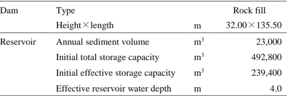
Outline of Horoka dam located in Hokkaido are shown in Table 1. The initial total storage capacity is small comparing to the annual sediment volume. The sedimentation problem occurred just 20 years after dam completion and, then after, excavation started. However, because of increasing sedimentation volume, the excavation became no more effective.
Table 1. Outline of Horoka dam
Dam Type Rock fill
Height×length m 32.00×135.50
Reservoir Annual sediment volume m3 23,000
Initial total storage capacity m3 492,800
Initial effective storage capacity m3 239,400
Effective reservoir water depth m 4.0
2.2 Objectives
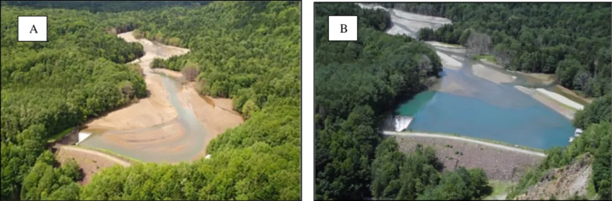
Horoka hydropower plant is unstable due to reservoir sedimentation. Especially, Horoka reservoir lost almost whole capacity by typhoons in 2016 which caused severe damages and some dikes’ breaches in Hokkaido. Although the excavation was implemented just after intake function of the hydropower plant was lost by sedimentation, it took 1.5 years until restarted generation.
While reservoir water level is lowered by hydropower operation, deposited sediment may flow into the hydropower plant which causes damages on mechanical equipment. Therefore, present effective water depth is reduced from original 4.0m to 2.0m.
Currently, excavation has been implemented as the sediment management at Horoka reservoir. The sediment has been transported to the disposal area which is 30km away from the dam site because the dam site is located in the area where sediment disposal is prohibited. It costs too much for sediment transportation, and economic and sustainable sediment management is needed.
To ensure functions of Horoka hydropower plant, flowing problems must be solved. Keep reservoir bed level low in front of the intake of the hydropower plant. Keep effective storage capacity
Figure. 1 Horoka reservoir A: After damaged by typhoons(2016.9) B: After resumption of generation(2018.5)
Figure 2.The intake of Horoka hydropower plant when water level was 2.6m (2018.10)
2.3 Study
A 2D numerical simulation of riverbed fluctuation was implemented to estimate the effect of sediment bypass tunnel on sediment management. Design flow discharge of the tunnel was selected as 80m3/s and 40m3/s by referring to Koshibu, Miwa and Solis
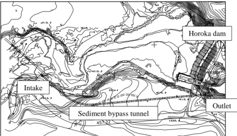
dams (Ohori et al., 2016). 80m3/s and 40m3/s are 5-year flood discharge of Horoka dam and its half, respectively. The intake of the tunnel was located at the reservoir upstream to prevent reduction of the reservoir capacity. The Layout of the sediment bypass tunnel is shown in Figure 3. In this numerical simulation, sediment bypass rate is calculated as shown in Figure 4.
The bypass tunnel will be operated while flow discharge is over 20m3/s which is the
minimum of annual maximum flow rate of Horoka dam, then the bypass tunnel would be used at least once a year.
Figure 3. Layout of sediment bypass tunnel at Horoka dam
Figure 4. Relationship between water bypass and sedimen bypass rate
2.4 Result
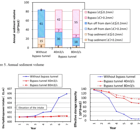
The results of the numerical simulation are shown in Fig 5-6. The annual trapped sediment volume decreases from 23,000m3 to 5,000m3 with the sediment bypass tunnel.
About 60% of total sediment volume was sluicing. The operation of the bypass tunnel kept riverbed level in front of the hydropower intake lower than that of without bypass tunnel and maintained more effective storage capacity. The bypass tunnel could make the sediment management efficient and reduced the risk of sedimentation.
615 620 620 615 615 615 615 610 610 615 3EP 610 610 615 610 610 600590 580570 0 0.1 0.2 0.3 0.4 0.5 0.6 0.7 0.8 0.9 1 0.0 0.1 0.2 0.3 0.4 0.5 0.6 0.7 0.8 0.9 1.0 Se d im e n t b yp as s ra te
Water bypass rate
Horoka dam
Sediment bypass tunnel Intake
Figure 5. Annual sediment volume
Figure 6. Change of river bed level in front of the hydropower intake and effective storage capacity with time
3 Futatsuno Dam
3.1 Outline
Outline of Futatsuno dam are shown in Table 2. Drawdown operation with existing facilities is not effective as sediment management because the current crest level of spillway gate is too high for sediment sluicing even by fully opened.
Table 2. Outline of Futatsuno dam
Dam Type Arch
Height×length m 76×210.6
Reservoir Annual sediment volume m3 956,000
Initial total storage capacity m3 43,000,000
Initial effective storage capacity m3 11,000,000
Effective reservoir water depth m 5.0
8 1 1 15 4 4 61 30 18 0 7 7 0 42 55 0 20 40 60 80 100 Without bypass tunnel 40m3/s 80m3/s A n n u al s e d im e n t vo lu m e (1 0 ^3 m 3 ) Bypass(d≦0.2mm) Bypass(d>0.2mm)
Run off from dam(d≦0.2mm) Run off from dam(d>0.2mm) Trap sediment(d≦0.2mm) Trap sediment(d>0.2mm) Bypass tunnel 600 601 602 603 604 605 606 607 1 2 3 4 5 6 7 R iv er b ed lev el in f ro n t o f th e h yd d ro p o w er in ta ke ( EL .m ) Year
Without bypass tunnel Bypass tunnel 40m3/s Bypass tunnel 80m3/s
Elevation of the intake
0 20 40 60 80 100 120 140 1 2 3 4 5 6 7 Ef fe ct iv e s to ra ge c ap ac it y ( 1 0 ^3 ×m3 ) Year
Without bypass tunnel Bypass tunnel 40m3/s Bypass tunnel 80m3/s
Figure 7. Futatsuno dam
3.2 Objective
The sedimentation causes upstream riverbed rise which increases flood damage risks in Futasuno dam reservoir. Mechanical excavation has been implemented to reduce the flood damage risk for 14 years. However, it is not effective because the annual sedimentation volume is more than that of possible excavation work. Futatsuno dam has also the problem of long-term persistence of high turbidity water which causes adverse environmental impacts.
To ensure the functions of Futatsuno hydropower plant, following problems must be solved. 100,000m3/year is acceptable limit volume for mechanical excavation at Futatsuno dam.
Reduce excavation volume to less than 100,000m3/year
Reduce the period of high turbidity water
Figure 8. A:Turbid water in Futatsuno dam, B:Turbid water from outlet of the hydropower plant
3.3 Study
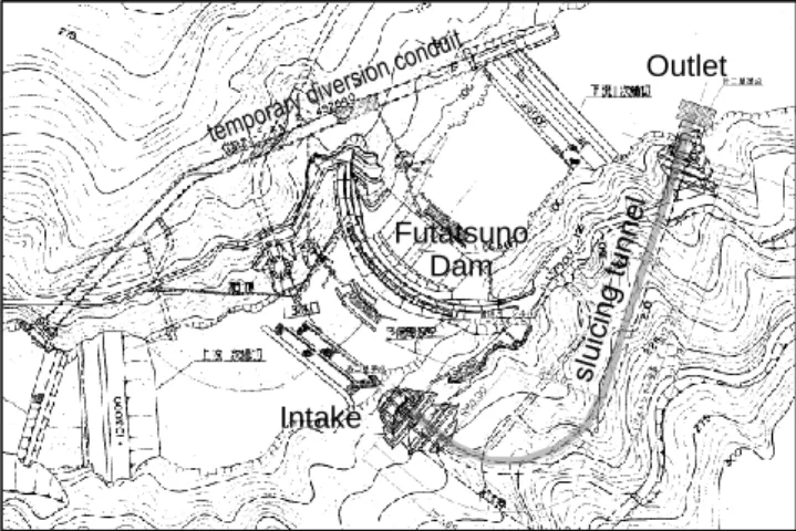
To estimate the effect of sluicing tunnel on sediment management, 1D numerical simulation of riverbed fluctuation is implemented. Key parameters are tunnel intake position, flow discharge of the tunnel and draw-down speed. The analysis prediction period is 50 years. The Layout of the bypass tunnel is shown in Figure 9. The intake is located at the reservoir upstream to prevent from the reduction of the capacity.
B A
A turbidity calculation when power generation restarts after water replacement with sluicing tunnel was implemented. The intake position of the sluicing tunnel was designed lower than spillway and makes the amount of water replacement larger. Figure 10 shows process of the calculation.
Figure 9. Layout of sediment slucing tunnel at Futatsuno dam
Figure 10. Process of calculation
3.4 Result
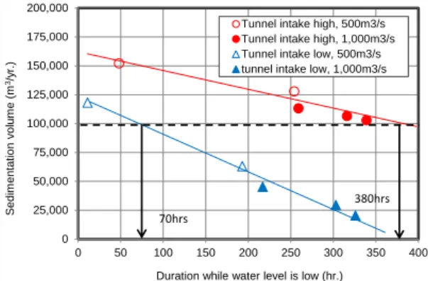
Figure 10 shows the result of the numerical analysis. This indicated that effect of the sluicing tunnel was dominated mainly by the position of tunnel intake and the sluicing operation time to keep reservoir water level low. To reduce excavation volume to less than 100,000m3/year, sluicing operation time needs 70 hours in case of high intake position and 380 hours in case of low intake one, respectively.
Table 3 shows the result of turbidity calculation. The sluicing tunnel reduced turbidity from 25 to 11 NTU. The sluicing tunnel could be effective for both sedimentation and turbidity control.
Table 3. Effect on turbidity control by sediment sluicing tunnel
Sluicing tunnel Turbidity when power generation restart (NTU) Reservoir average Water from outlet
Without tunnel 47 25 With tunnel 22 11 Futatsuno Dam Intake Outlet
Calculate the weight of suspended solid in reservoir after water replacement (1) Calculate the weight of suspended solid in clear water stored (2) Calculate the average turbidity of the reservoir, {(1)+(2)}/total water volume (3)
Figure 11. Relationship between the sluicing operation time and yearly sedimentation volume
4 Conclusion
This paper presents the study of sediment management at Horoka dam and Futatshuno dam in J-Power Company. We found that the sediment bypass tunnel and sluicing tunnel could be effective by the numerical analysis.
At Horoka dam, the operation of bypass tunnel can reduce excavation volume and keep riverbed level in front of the intake low and effective storage capacity.
At Futatsuno dam, the operation of sluicing tunnel can reduce excavation volume to less than 100,000m3/year which is acceptable volume of excavation. Moreover, it will be
effective for turbidity control.
We will design the appropriate these bypass tunnels considering various aspects such as their cost and impacts on river environment etc.
References
Hideyoshi, O., Masato, O. and Katsuhiro, K. Case analysis of sediment bypass tunnel (Switzerland, Taiwan and Japan), Report of Water Resources Environment Research Institute, 29-34, 2016 Okumura, H. and Sumi, T.(2013) Influece of sedimintation progress in storage reservouirs on hydropower
plant operation. Journal of JSCE B1, Vol.69, No.4, I_979-984.
Authors
Tomotake Imaoka Hirofumi Okumura
Civil & Architectural Engineering Dept, Electric Power Development Co., Ltd., Japan
Chihaya Onda
West Regional Headquarter, Electric Power Development Co., Ltd., Japan Tetsuya Sumi
Disaster Prevention Research Institute, Kyoto University, Japan Email: tomotake_imaoka@jpower.co.jp 0 25,000 50,000 75,000 100,000 125,000 150,000 175,000 0 50 100 150 200 250 300 350 400 S ed im en tat ion v ol um e (m 3/y r.)
Duration while water level is low (hr.) Tunnel intake high, 1,000m3/s Tunnel intake low, 500m3/s tunnel intake low, 1,000m3/s
70hrs