在耐延遲網路中依人氣與接觸關聯為基礎之訊息散播與優先排程之轉發機制 - 政大學術集成
59
0
0
全文
(2) 在耐延遲網路中依人氣與接觸關聯為基礎之訊息散播 與優先排程之轉發機制 Popularity Spray and Utility-based Forwarding Scheme with Message Priority Scheduling in Delay Tolerant Networks. 研 究 生:陳英明 指導教授:蔡子傑. 立. Student:Ying-Ming Chen Advisor:Tzu-Chieh Tsai 治 政 大. ‧ 國. 學. 國立政治大學 資訊科學系. Nat. A Thesis. er. io. sit. y. ‧. 碩士論文. n. submitted to a Department of Computer v Science. i l C n NationalhChengchi i U e n g c hUniversity. in partial fulfillment of the Requirements for the degree of Master in Computer Science. 中華民國一零二年一月 January 2013.
(3) 在耐延遲網路中依人氣與接觸關聯為基礎之訊息散播與優先排程 之轉發機制. 摘要. 在耐延遲網路環境下,訊息資料的傳送依賴於節點間因移動性而產生的間. 政 治 大 斷性連結,並使用「儲存並攜帶再轉送」的方式傳遞至其目的地,因此網 立. ‧ 國. 學. 路中各個節點的儲存空間以及與其他節點的「接觸關連性」將扮演訊息傳 遞品質的重要因素。. ‧. sit. y. Nat. 本論文提出一以 Flooding-based 與 Forwarding-based 兩類路由協定為基. a. er. io. 礎設計結構、並加以擴充考量訊息優先權於轉發機制之三階段式路由演算. n. v l 法。其主要概念在於利用網路中節點的移動特性來週期性地預測節點與節 ni Ch. engchi U. 點間未來的相遇人氣做為訊息散播時的分配權重、及以累計相遇時間之比 率為接觸關聯性做為訊息是否進一步轉送之依據、最後並在訊息傳送順序 上加入優先權排序的策略。根據與其他路由演算法的模擬實驗,顯示我們 所提的演算法能有較高的訊息傳遞成功率、相對低的資源耗費、以及差異 化訊息傳送服務的效能。 關鍵字:耐延遲網路、路由協定、優先權、優先排程、接觸關聯性. i.
(4) Popularity Spray and Utility-based Forwarding Scheme with Message Priority Scheduling in Delay Tolerant Networks.. Abstract. Delay Tolerant Networks (DTNs) use the “Store-Carry-and-Forward” approach. 政 治 大. to deliver the messages to the destinations. It relies on the intermittent link that. 立. occurs when two nodes contact each other due to mobility.. Therefore, the. ‧ 國. 學. buffer and “contact association” of nodes are two important factors that affect the delivery performance.. ‧. In this thesis, we propose a three-phase algorithm (SFMS: Spray and. Nat. sit. y. Forwarding scheme with Message Scheduling) that integrates the concepts of. er. io. flooding-based and forwarding-based protocols, and considers message priority.. n. a l is to periodically predicti vthe contact popularity and The main idea of SFMS. n U e such h iwe can determine the fast message n g cthat contact association among nodes,. Ch. spraying and efficient forwarding strategy. Furthermore, we come up with a message scheduling mechanism to enhance the resource allocation. Simulation results show that our scheme has a better performance for delivering messages. Besides, it also achieves a differential delivery performance for different priorities of messages while maintaining a better resource allocation. Keywords:Delay tolerant networks, Routing, Priority, Scheduling, Contact association ii.
(5) 誌謝辭. 將近二十年的全職學生生涯,終於即將告一段落,在研究所這兩年來,經歷了許多 磨練,像是透過 Meeting 輪值、構思國科會計畫以及論文的撰寫,都大大地促使自己必 須不斷地突破能力上的瓶頸,並從整個過程中培養起了如何獨立做研究、發現並解決問 題的邏輯思考能力。然而,本論文能夠順利完成,其中最功不可沒的非為我的指導教授 蔡子傑老師莫屬,在每次的會議中,老師總是文思泉湧,不但會給予許多有價值的研究. 政 治 大. 方向以及精闢的建言,並教導我們如何且縝密、有條理地思考所遇到的研究問題,也感. 立. 謝老師總是能夠抽空和我討論論文的細節,讓我撰寫論文的過程可以更加嚴謹、有效率,. ‧ 國. 學. 在此由衷地感謝蔡老師對我的指導與付出。另外,對於同樣愛好打羽球的我,也從老師 身上學到了許多寶貴的實戰技巧與觀念,希望未來仍有機會能常回學校和老師一起切磋. ‧. 球技。還有也特別感謝我的口試委員 林宗男教授、吳曉光教授、周承復教授、陳伶志. Nat. sit. y. 教授,感謝教授們於口試時給予的寶貴建議與指導,讓本論文得以更臻完善。. n. al. er. io. 緊接著,我要感謝文卿、勇麟、界誠、泰榮、偉敦、凱禎、賀翔、彥嵩等學長姐,. i n U. v. 感謝學長姐們為實驗室帶來許多活動與歡樂,使得枯燥的研究生活增添了不少樂趣,同. Ch. engchi. 時也感謝學長姐在課業上的指點以及生活上的照顧,感謝勇麟學長介紹校內工讀的機會 給我,讓我得以兼顧學業以及生活上的支應,感謝凱禎學長每次不吝嗇的和我分享美食。 感謝曾經一起在實驗室奮鬥的欣諦、昶瑞,特別感謝欣諦耐心地為我解釋許多撰寫程式 時遇到的問題。感謝實驗室的學弟妹 煜泓、建淳、宇軒、筱璇、凱柔,謝謝你(妳)們幫 我分擔了許多研究上的工作,還有你(妳)們的加入也讓實驗室變得更有朝氣。謝謝富爸 爸冠傑、郁翔曾經一起分工找考古題答案。謝謝阿衣好心借我自動鉛筆。謝謝誠誠課餘 時陪我打羽球,也謝謝全體系羽的同學們,謝謝你(妳)們每次都撥空去佔場地,讓我在 研究所的日子裡可以依舊熱血。感謝系上 嘉蓮助教、儷文助教、淑怡助教提醒我很多 課業與撰寫論文的相關規定,尤其感謝淑怡助教在我擔任總務時給予了許多的幫助、並 iii.
(6) 且不厭其煩地解惑我在報帳時遇到的問題。感謝英文系 玉屏助教、綺如助教、莉華助 教、梅祥助教,以及語言所 惠鈴助教,謝謝妳們提供我校內工讀的機會,也讓我能夠 磨練許多電腦技能,特別感謝惠鈴助教在我衝刺論文的時候給予我很彈性的上班時段, 讓我能夠優先處理論文相關的事務。還有感謝英文系 惠玲老師可以見面一次之後就記 住我的名字,讓我感到非常的窩心。感謝語言所常在電腦教室出沒的同學們,讓我每次 打工時都能沉浸在歡樂的氣氛中,特別是捧芃、胖口亨、涵絜、David、感謝你(妳)們的 活潑可愛與大、小活動的邀約,讓我能更融入與適應語言所這個大家庭,以及認識更多. 政 治 大 在大學時的指導教授 雅芬老師,在真正進入研究所之前就開始指導我日後做研究時的 立 的人,也因為捧芃我才能享受一次只有我一位男生和其他正妹們的歡樂下午茶。感謝我. ‧ 國. 學. 基礎知識與態度,並感謝世穎老師、華青老師、百鈞老師、春宏老師、榆佩姐、小萱學 姐在大學生涯中對我的諸多照顧。感謝傅費費幫我一起整理舊房子,並妥善照顧了兩年,. ‧. 讓我減少了許多煩惱。感謝我高中三年的導師 建仁老師,您的諄諄教誨以及對學生無. sit. y. Nat. 私的奉獻,讓我高中三年學習下來有如脫胎換骨,今日我能夠完成此碩士學位,您當時. io. er. 的細心指導對我絕對有非常大的幫助,在您的教導之下,不只是為未來打下了重要的基 礎,也從您身上學到了許多做人、處事的態度,這都是日後受用無窮的珍貴寶藏。以及. al. n. v i n Ch 感謝佩俞老師在我高三衝刺統測時費心幫我準備許多營養食品,讓我每天都可以精神飽 engchi U 滿、全神貫注地學習。也感謝麗英老師、心儀老師、寬達老師、淑伶老師、清波教官對 我的用心教導,讓我找回許多已經放棄的學科的信心。 最後,也是最重要,我要感謝我的父母親,因為有您們對我的百般包容以及無怨無 悔的支持,讓我在研究所這兩年多日子裡可以毫無後顧之憂地專心於學業,謝謝您們在 我身上付出了二十多年的光陰,希望將來能夠發揮所學為國家、社會盡一份力,讓辛苦 養育我的父母親以我為榮,也報答父母親的養育之恩。 在此雖無法一一列述所有關心我、支持我的所有親朋好友,但我仍會永遠將你(妳) 們對我的好記在心裡面,謝謝你(妳)們。. iv.
(7) TABLE OF CONTENTS. CHAPTER 1 Introduction ..................................................................................... 1 1.1 Background .............................................................................................. 1 1.2 Motivation ................................................................................................ 2 1.3 Our Goal ................................................................................................... 5. 政 治 大 CHAPTER 2 Related Work 立 ................................................................................... 6 1.4 Organization ............................................................................................. 5. ‧ 國. 學. 2.1 Flooding-based Routing Protocol ............................................................ 7 2.1.1 Direct Delivery Routing Protocol .................................................. 7. ‧. 2.1.2 Epidemic Routing Protocol ............................................................ 7. sit. y. Nat. 2.1.3 Spray and Wait Routing Protocol ................................................... 8 2.2 Forwarding-based Routing Protocol ........................................................ 8. er. io. n. 2.2.1 Gradient Routing Protocol.............................................................. 8 a v. i l C n 2.2.2 Location-based Routing h e n gProtocol c h i U................................................... 9 2.3 Main Schemes for Our Design Concepts ................................................. 9 2.3.1 A Message Priority Routing Protocol for Delay Tolerant Networks (DTN) in Disaster Areas [17].......................................................... 9 2.3.2 Utility-based Distributed Routing in Intermittently Connected Networks [14] ................................................................................ 12 2.3.3 IMPLEMENTING MESSAGE PRIORITY POLICIES OVER AN 802.11 BASED MOBILE AD HOC NETWORK [11] ................ 13 CHAPTER 3 Spray and Forwarding scheme with Message Scheduling ........... 15 v.
(8) 3.1 Popularity Spray Phase........................................................................... 15 3.2 Utility-based Forwarding Phase ............................................................. 19 3.3 Message Forwarding with Priority Scheduling Phase ........................... 23 3.4 Buffer Management Strategy ................................................................. 26 CHAPTER 4 Simulation and Results ................................................................. 29 4.1 Performance Metrics .............................................................................. 29 4.2 Simulation Setup .................................................................................... 30. 政 治 大. 4.2.1 Simulation Settings....................................................................... 31. 立. 4.3 Simulation Results .................................................................................. 32. ‧ 國. 學. 4.3.1 Performance of Different Buffer Sizes ......................................... 32 4.3.2 Performance of Different Node Densities .................................... 40. ‧. CHAPTER 5 Conclusions and Future Work ....................................................... 45. Nat. n. al. er. io. sit. y. REFERENCES .................................................................................................... 46. Ch. engchi. vi. i n U. v.
(9) LIST OF TABLES. Table 1: An example of Node State Table ........................................................... 20 Table 2: Parameters of simulation setting ........................................................... 31. 立. 政 治 大. ‧. ‧ 國. 學. n. er. io. sit. y. Nat. al. Ch. engchi. vii. i n U. v.
(10) LIST OF FIGURES. Figure 1: Mobility scenario assumption................................................................ 4 Figure 2: Selection of message priority [17]. ...................................................... 10 Figure 3: Area covered by route discovery floods [16]. ..................................... 11 Figure 4: Time-Distance problem of carry-and-forward method in DTNs ........ 12. 政 治 大 Figure 6: Prioritized waiting 立 time mechanism [11]............................................... 13. Figure 5: Priority queuing approach [11] ............................................................ 13. ‧ 國. 學. Figure 7: Prioritized backoff time distribution mechanism [11]......................... 14 Figure 8: Message replication process ................................................................ 16. ‧. Figure 9: Popularity Spray .................................................................................. 18. sit. y. Nat. Figure 10: Enhancement ratio of message spraying by Popularity Spray .......... 19 Figure 11: An example of message forwarding .................................................. 22. er. io. n. Figure 12: Average moving a correlation of node moving v pattern. ....................... 23. i l C n Figure 13: An example of calculating forwarding sequence ................ 25 h e n gmessage chi U. Figure 14: Message transmission queue ............................................................. 26 Figure 15: Buffer management strategy .............................................................. 27 Figure 16: A snap shot of the ONE simulator ..................................................... 30 Figure 17: Delivery ratio vs. Different buffer sizes ............................................ 32 Figure 18: Overhead ratio vs. Different buffer sizes........................................... 33 Figure 19: Delivery delay vs. Different buffer sizes ........................................... 33 Figure 20: Delivery ratio vs. Individual message priority of 5MB buffer .......... 35 Figure 21: Delivery ratio vs. Individual message priority of 25MB buffer ........ 36 viii.
(11) Figure 22: Delivery ratio vs. Individual message priority of 50MB buffer ........ 36 Figure 23: Delivery ratio vs. Individual message priority of 100MB buffer ...... 37 Figure 24: Delivery delay vs. Individual message priority of 5MB buffer ........ 38 Figure 25: Delivery delay vs. Individual message priority of 25MB buffer ...... 38 Figure 26: Delivery delay vs. Individual message priority of 50MB buffer ...... 39 Figure 27: Delivery delay vs. Individual message priority of 100MB buffer .... 39 Figure 28: Delivery ratio vs. Different node densities ........................................ 41. 政 治 大. Figure 29: Overhead ratio vs. Different node densities ...................................... 41. 立. Figure 30: Delivery delay vs. Different node densities ...................................... 42. ‧ 國. 學. Figure 31: Delivery ratio gap vs. Different node densities ................................. 43 Figure 32: Overhead ratio gap vs. Different node densities ............................... 43. ‧. n. er. io. sit. y. Nat. al. Ch. engchi. ix. i n U. v.
(12) CHAPTER 1 Introduction. 政 治 大 networks could be divided into 立. 1.1 Background Traditionally, wireless. ‧ 國. In the infrastructure mode, nodes can communicate with each. 學. non-infrastructure mode.. infrastructure mode and. other, and connect to the Internet through a base station (BS) or an access point (AP).. ‧. However, communication in the non-infrastructure mode does not need the help of BS or AP.. io. al. n. Networks.. This type of communication is also called Ad Hoc. er. to relay the data to the destined node.. sit. y. Nat. When a node wants to communicate with another one, it relies on other nodes in the network. Over the past decade,. v i n C hTolerant NetworksU (DTNs), Delay engchi. the emergence of a new. network architecture that could also be viewed as a kind of ad hoc networks, have attracted lots of the interest of many researchers.. The main distinctive feature of delay tolerant. networks is that a complete end-to-end path from the source to the destination may not always be guaranteed to exist due to the sparse topology and mobility [14] compared with traditional ad hoc networks, and in such environment, message transferred by Store-Carry-and-Forward approach by opportunistic contacts between nodes, hence delay tolerant networks also be seen as opportunistic networks [4]. There are many studies which proposed the idea of routing messages in DTNs [3-9, 1.
(13) 13-15, 17-20].. Most of them are focusing on the principle that goes to make communication. possible and efficient between the source and the destination even under an intermittent connectivity environment. From the view point of message replication, these studies could be divided into two categories: Flooding-based approach and Forwarding-based approach [1, 2]. replicates messages to every contact node in the network.. The former. Flooding-based approach could. not only achieve a higher delivery ratio and a lower delivery delay, but also cause a higher. 政 治 大. overhead ratio and need huge buffer space; the latter requires some network information to. 立. determine whether to make another replication of a message and forward it to the contact. ‧ 國. 學. node.. Forwarding-based approach has an acceptance delivery ratio, latency time and low. overhead ratio, but the needed information may not be easily to acquire in DTNs.. ‧. On the other hand, smart phones have been more and more popular.. Nat. y. According to the. sit. market survey [24-25], the popularity of smart phones in the U.S. is as high as 54.9% in the. n. al. er. io. first half of 2012, and would be continuously growing in the near future.. i n U. Therefore, letting. v. everyone in a specific region holds one smart phone will be a reasonable assumption.. Ch. engchi. Furthermore, almost every smart phone is equipped with at least one communication module that is suitable for communicating in a non-infrastructure mode like Wi-Fi and Bluetooth.. 1.2 Motivation In the DTNs, message delivering relies on the intermittent link between nodes due to their mobility.. In reality, node’s mobility will usually has a kind of regular moving pattern. according to the nature of the node.. Based on this specific mobility we could find a. prediction of future contact information by history of a period of time. There are some studies [8, 14-15, 20] which use community model to simulate node 2.
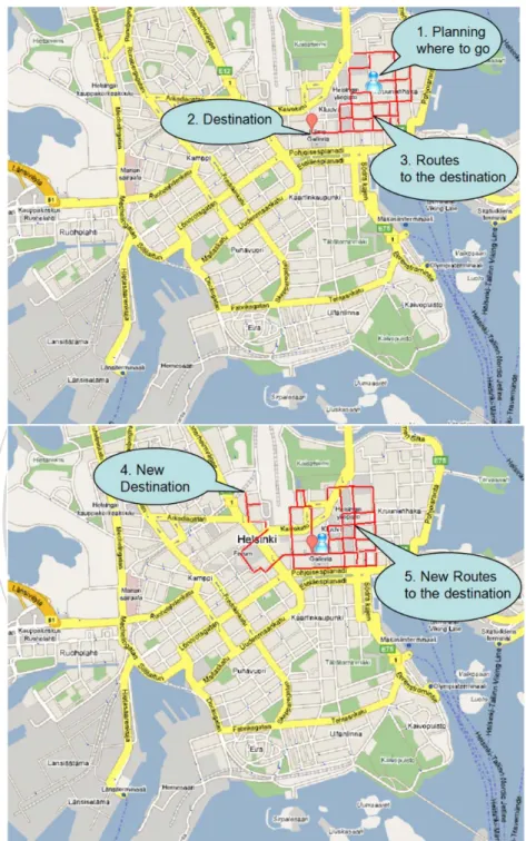
(14) mobility pattern in order to make the moving scenario more realistic.. The basic concept of. community model is that it assigns each node in the network some fixed positions to move with corresponding probability. The assigned positions are like node’s home community, office community etc.. For example, if a node is in its home community, it may have a. higher probability to go to its office and a lower probability to go to some other places like a shopping mall.. A node in the community mobility model will choose the new destination to. move with the pro-assigned probability whenever it reaches the current destination, and the. 政 治 大. moving process of a node will continue until the end of the simulation time.. 立. This is mainly. to simulate the real-life of human, through making the nodes have their own living. ‧ 國. 學. preferences and moving routines.. However, in real life, the situation we are dealing with may not always have a. ‧. community property. For example, traveling in a foreign country or a famous scenic spot,. y. Nat. Hence,. sit. there might be a lot of travelers in such area without the community moving pattern.. n. al. er. io. we would have to propose a new moving property concept for those travelers so that the new. i n U. v. moving property can be properly applied to the traveling scenario.. Ch. engchi. Provided that we are in a famous foreign city, we may not clearly know the geographic information about the place, but we still have a destined site to go. want to visit all the scenic spots on our way to the destination.. Somehow we may also. Therefore, instead of directly. moving to the site, we would have a period of time to move around in an area for visiting, and gradually move to the site. We will randomly choose another site in the city to go when getting the destination.. The mobility scenario described above is shown in Figure 1.. Where the map used to illustrate is Helsinki in Finland that derived from the ONE simulator [21].. 3.
(15) 立. 政 治 大. ‧. ‧ 國. 學. n. er. io. sit. y. Nat. al. Ch. engchi. i n U. v. Figure 1: Mobility scenario assumption. Because of the popularity of smart phones, almost everyone will have one in the near future, and the communication functions like Wi-Fi and Bluetooth are basically equipped with it.. Therefore, we could take everyone in this city as a node with communication capability,. 4.
(16) and the contact information applied to our algorithm can be acquired by the built-in communication modules (when two nodes are inside the transmission range of each other). The function of GPS will expected to be closed, because it causes more power consumption. Besides, among the messages, different kinds of messages may have different priorities, and because of the specific characteristics in the DTNs, node’s buffer and the contact time between nodes are two of the most important factors that affect the delivery performances [2]. Therefore, how to allocate these resources to different kinds of messages would also be important.. 立. 1.3 Our Goal. 政 治 大. ‧ 國. 學. Our goal is to have users who have a regular moving pattern in a region as what we mentioned in section 1.2 enable to deliver messages to other users with a more efficient routing protocol. ‧. while making a differential delivery performance with different message priorities.. y. Nat. sit. Therefore, we would like to design a message routing protocol which (1) works without. n. al. er. io. the aid of GPS, (2) takes the advantages of flooding-based and forwarding-based protocols, (3). i n U. v. considers the message priorities during the process of message transmission and (4) allocates the resources more properly.. Ch. engchi. Note that the resources here, we mainly focus on the buffer and. the transmission sequence of messages.. 1.4 Organization The rest of this thesis is organized as follows.. Chapter 2 introduces related works about. common routing protocols and key schemes of our design concepts in DTNs. describes our proposed design in detail. performance evaluation.. Chapter 3. Chapter 4 presents simulation results of. Eventually, we summarize our work and discuss some directions. for future work in Chapter 5. 5.
(17) CHAPTER 2 Related Work. 政 治 大 in DTNs and priority-related schemes. 立. In this chapter, we will introduce the research of routing protocols that are commonly referred. ‧ 國. 學. In the beginning, we will introduce the main concepts of the two categories of flooding-based and forwarding-based routing protocols that we have mentioned in Chapter 1,. ‧. enumerate a number of representative routing protocols, and make a brief summary of these. sit. y. Nat. protocols.. io. al. er. Next, we will describe the key concepts that we referred to in this thesis in detail, and list. n. a couple of related research.. Ch. engchi. 6. i n U. v.
(18) 2.1 Flooding-based Routing Protocol The basic concept in this category of routing protocols is to increase the replication ratio of message in the network and to enhance the message delivery ratio. A node will replicate the messages to the contact nodes unconditionally. Protocols belong to this category are easier to implement because of they do not require any other information about the network, but the delivery overhead may potentially heavily depends on the degree of message replication.. 政 治 大. 2.1.1 Direct Delivery Routing Protocol. 立. In this routing protocol, a message will be transmitted only when the source node contacts its. ‧ 國. 學. destination node.. This way of designing is to keep a lower buffer requirement because the. node will only directly transmit a message to its destination, instead of by other relay nodes.. ‧. However, there may be the longest message transmission delay from the source to the. y. Nat. This approach has mainly worked on communication between mobile nodes. sit. destination.. n. al. er. io. and fixed gateways [3].. Ch. 2.1.2 Epidemic Routing Protocol. engchi. i n U. v. Contrary to the direct delivery routing protocol, node using Epidemic [5] routing protocol will maintain a summary vector [6] to record the ID of messages which are currently stored in the node buffer.. Whenever two nodes contact each other, they will first exchange their summary. vector, then transmit the messages that their IDs do not exist in the vector.. In brief,. Epidemic will try to send messages to all nodes to enhance the delivery ratio even if these nodes are not the destined one for a message. Theoretically, Epidemic would not only have the highest delivery ratio and the lowest delivery delay, but also the highest overhead ratio when the buffer is unlimited. 7.
(19) 2.1.3 Spray and Wait Routing Protocol A trade-off mechanism between Direct Delivery and Epidemic routing protocol, the copies of a message will be restricted to a constant number, also called L copies, which means that a message will have at most L copies during the whole delivery process in the network [7].. By. this approach, Spray and Wait can overcome the defect of heavy delivery overhead that happens in Epidemic, and acquire a better delivery performance than Direct Delivery due to the copies of a message increase slightly.. 立. 政 治 大. 2.2 Forwarding-based Routing Protocol. ‧ 國. 學. This category of routing protocols takes additional information into consideration such as network topology and node’s location to determine which node reaches the forwarding. ‧. criterion that could differ from different protocols to relay the message. Theoretically, routing. y. Nat. sit. messages in these protocols could have a better performance, because the more information a. n. al. er. io. protocol gets, the more accurate decision it could make for delivering the messages. In order. i n U. v. to get more information, protocols need to monitor the network topology almost all the time.. Ch. engchi. On the other hand, some protocols may need the aid of GPS to calculate the information which is needed. However, the use of GPS may be a heavy burden on battery.. 2.2.1 Gradient Routing Protocol Every node in this routing protocol will be assigned a weighted value to judge the suitability of a node for delivering the message to a given destination.. A node transmits a message to. another node only when that one has a higher weighted value for the message to its destination, and message delivered along the gradient of improving weighted value would be guided to its destination. PROPHET [8], a routing protocol proposed by Lindgren et al., 8.
(20) uses history of encounters and transitivity to evaluate the probabilities (weighted value) of contact among nodes.. The higher contact frequency of a pair of nodes, the higher contact. probability they would have.. 2.2.2 Location-based Routing Protocol This routing protocol makes message forwarding decision by taking advantage of GPS (Global Positioning System) to acquire position-related information.. 政 治 大. Also, before. transmitting messages, it will evaluate if the probability (weighted value) of the contact node. 立. The shortest distance [10] or minimum hop counts from the source to the. destination is often used as the forwarding criterion.. 學. ‧ 國. is higher.. Location-based routing protocol will. have a better performance on delivery ratio and delivery overhead compared with Epidemic. ‧. routing protocol, which is proven by Lebrun et al [9].. n. er. io. al. sit. y. Nat. 2.3 Main Schemes for Our Design Concepts. i n U. v. In this section, we will introduce three schemes that provide us some directions to design our algorithm.. Ch. engchi. 2.3.1 A Message Priority Routing Protocol for Delay Tolerant Networks (DTN) in Disaster Areas [17] This research proposed a modification version of Spray and Wait [7] protocol and applied it to a disaster area.. The main idea of this research is to deliver the message more efficient by. modifying the “wait step” in Spray and Wait.. It would have the messages that achieve a. certain criterion a further chance to be forwarded to another node to enhance the message delivery ratio. 9.
(21) In this protocol, every node has a Node Meeting Table (NMT) to record the latest encounter time (LET) when contacting other nodes.. Messages will be assigned a priority. from High, Middle and Low, depending on a given threshold, as shown in Figure 2.. 立. 政 治 大. ‧. ‧ 國. 學 y. Nat. n. al. er. io. sit. Figure 2: Selection of message priority [17].. i n U. v. The Threshold in Figure 2 is determined experimentally, and the threshold is. Ch. engchi. proportional to the buffer size. The LET is calculated by using the current time to minus the NMT value of contact node corresponding to the message destination of the requesting node. The idea of LET in this scheme is derived from the FRESH algorithm [16]. Originally, the FRESH algorithm is used to find a routing path from a source node to a destination node in mobile ad hoc networks as shown in Figure 3.. A source node will find. the node which has the shortest time after it last encounter the destination node, and repeat this action node by node until find the destination node. The FRESH algorithm could make a directional trace toward the destination (the darker gray surface).. It decreases the overhead. in an omni-directional route discovering (the light gray surface) approach. 10.
(22) In [17], the authors use the same concept called LET in DTNs to represent the degree of distance from the source to the destination.. In order to increase the message delivery ratio,. the message with a shorter LET will have a further chance to be forwarded to another node when the message’s destination can not be found in the message spray phase.. 立. 政 治 大. ‧. ‧ 國. 學. n. er. io. sit. y. Nat. al. Ch. engchi. i n U. v. Figure 3: Area covered by route discovery floods [16].. However, applying the concept of the FRESH algorithm to DTNs might cause a problem which is shown in Figure 4.. As we can see in Figure 4, node(A) contacts node(D) at time T1,. node(B) contacts node(D) at time T2, and node(A) contacts node(B) at time T3. point of time, T2 has a more recent contact time than T1 to T3.. From the view. But, from the view point of. distance, when node(A) and node(B) contacts at T3, we can view them as the same place, the two distances, node(A) to node(D) and node(B) to node(D), are almost the same. 11. Therefore,.
(23) carrying a message to node(D) by node(A) or node(B) would make no difference in DTNs if we only consider the most recent contact time with the destination.. Figure 4: Time-Distance problem of carry-and-forward method in DTNs. 政 治 大. 2.3.2 Utility-based Distributed Routing in Intermittently Connected Networks [14]. 立. The term utility could also be called weighted value because it is usually used to evaluate the. ‧ 國. 學. node’s probability for delivering a message to its destination.. In PROPHET [8], the utility. (weighted value) is the history of contact frequency and transitivity.. ‧. Nat. The community mobility model [23] which simulates. sit. step”, is called forwarding phase.. But a modification in the “Wait. y. This research is a kind of Spray and Wait [7] as well.. n. al. er. io. human’s behavior in a social network is applied to this research.. i n U. Based on the community. v. mobility pattern, this research proposed a new utility model called contact time utility to. Ch. engchi. evaluate the meeting probability in the forwarding phase.. The probability here is calculated. from the total contact time with other nodes in a period of time shown in formula (1). 𝑃𝑃(𝑖𝑖,𝑗𝑗 ) =. 𝑇𝑇(𝑖𝑖,𝑗𝑗 ) 𝑇𝑇(𝑖𝑖). (1) [14]. Where P(i,j) represents the probability of node (i) meets node(j), T(i,j) represents the total time of node(i) meets node(j) in a time period T(i) which represents node (i) leaving its home community in two consecutive times. The contact duration utility is proven [15] that it could be more accurate than the contact frequency utility to evaluate the delivery probability between a pair of nodes in DTNs,. 12.
(24) especially in high mobility environments. The authors also divide messages into different priorities that are decided by the application.. The concerning of discriminating messages is that messages may have different. urgencies, and the message delivery sequence should consider the kinds of urgencies because the transmission time at every contact may be very short. The buffer in DTNs is also a precious resource, therefore, the authors proposed a buffer management mechanism.. It has message that with a higher utility would have a higher. 政 治 大. chance to keep in the buffer to enhance the delivery performance.. 立. ‧ 國. 學. 2.3.3 IMPLEMENTING MESSAGE PRIORITY POLICIES OVER AN 802.11 BASED MOBILE AD HOC NETWORK [11]. ‧. Nat. But, different opportunities (priorities) may. sit. takes all of the data packets as the same priority.. y. Standard IEEE 802.11 does not provide differential services for different kinds of data, it. n. al. er. io. need to be given to data packets to access media in some situations like military environments. i n U. v. in which the emergency such as combat message [12] should have a higher priority than. Ch. i e n g c h Therefore,. others to acquire the transmission right.. this research proposed an. implementation that modifies the standard IEEE 802.11 protocol to provide the differential services for the messages.. The three mechanisms that proposed in this scheme are shown in. Figure 5, Figure 6 and Figure 7.. Figure 5: Priority queuing approach [11] Figure 6: Prioritized waiting time mechanism [11] 13.
(25) Figure 7: Prioritized backoff time distribution mechanism [11]. 立. 政 治 大. First Out (FIFO) method is applied to both queues.. 學. ‧ 國. In Figure 5, different queues are used to buffer different kinds of messages, and First In In Figure 6, messages in different. queues will have different DIFSs, which means different waiting time before trying to send. ‧. messages.. The mechanism shown in Figure 7 gives message with a higher priority to have a. y. Nat. sit. higher opportunity to get a shorter contention window.. n. al. er. io. From this research, we could get an idea of how to decide the message delivery sequence. i n U. v. meanwhile avoiding the condition of starving for the message with a lower priority.. Ch. engchi. 14.
(26) CHAPTER 3 Spray and Forwarding scheme with Message Scheduling. 政 治 大. In this chapter, we will propose a routing protocol on improving some of the problems that we. 立. mentioned in the former chapters.. ‧ 國. 學. Our scheme could be divided into three parts, (1) Popularity Spray Phase, (2) Utility-based Forwarding Phase, and (3) Message Forwarding with Priority Scheduling Phase.. ‧. In the following, we will describe each of the three phases in detail, including how to improve. sit. y. Nat. some of the problems that exist in current protocols, and a message scheduling mechanism. io. n. al. er. that we design to achieve a differential performance for messages with different priorities.. 3.1 Popularity Spray PhaseC h e. ngchi. i n U. v. Routing message in DTNs basically relies on the opportunistic contacts between nodes, so the message diversity that indicates how a message spreads in nodes would have an important factor to affect the delivery performance.. If every message only exists in one node, the. chance of the node contacts the message’s destination would be very small and may cause a longer time to successfully deliver.. On the other hand, if every message which is carried by. too many nodes in the same time, the overhead ratio would be very heavy.. Even if with a. kind of utility to determine the forwarding decision, the utility is just a referable probability. It is not absolute in accordance with the future behavior after all. 15. Another situation is that if.
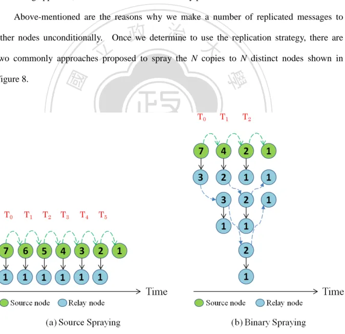
(27) all of the contact nodes in a period of time have a lower utility, the message will not be further forwarded in that time.. In other words, the message may still be carried by a single node for. a certain time in a simply forwarding-based approach.. Therefore, we argue that a certain. number of message copies for a newly created message (we called N copies, which is also applied in [7,14-15, 20]) should initially be replicated to other nodes, even if in a utility-based forwarding approach, in order to enhance the delivery performance. Above-mentioned are the reasons why we make a number of replicated messages to other nodes unconditionally.. 政 治 大. Once we determine to use the replication strategy, there are. 立. two commonly approaches proposed to spray the N copies to N distinct nodes shown in. ‧. ‧ 國. 學. io. sit. y. Nat. n. al. er. Figure 8.. Ch. engchi. i n U. v. Figure 8: Message replication process. 16.
(28) In Figure 8(a), it shows a simplest way of spraying message which has all the N copies been sprayed to N distinct nodes only by the source node [7]. In Figure 8(b), it shows a better choice called Binary Spraying [7] that is proven to be a minimum spraying delay if the nodes move with IID.. In Binary Spraying, every node (source nodes or relay nodes) can participate. in the spraying process by using a binary approach with which the sender will keep �. Remains of 𝑁𝑁 2. � copies, and the receiver will keep �. Remains of 𝑁𝑁 2. � copies till the N remains only. one in the nodes. As we can see, Binary Spraying could have a less spraying delay than. 政 治 大. Source Spraying in the process of spraying N message copies to N distinct nodes.. 立. Furthermore, the delay time in the spraying process also affects the following delivery. ‧ 國. 學. performance that is proven by [14].. Binary Spraying would be an optimal spraying algorithm if the node mobility is IID, and. ‧. some research [14-15, 20] use the Binary Spraying in Community-based mobility model,. y. Nat. sit. which is proposed to simulate moving trace of realistic human daily life.. However, nodes in. n. al. er. io. Community-based model will predefine several different kinds of moving preferences.. i n U. v. other words, nodes will have different probabilities to move to somewhere.. Ch. engchi. phenomenon of node moving pattern may not be IID characteristic anymore.. In This. Therefore,. simply applying the Binary Spraying to the Community-based model (non-random moving pattern) may not have an expected effect.. We argue that the original Binary Spraying should. be adjusted to apply to a specific moving pattern such as Community-based model.. Hence,. we propose a Popularity Spray approach to be a more suitable message spraying method for a non-random mobility model. When nodes are moving with a specific mobility pattern, they would have their own predefined attributes. Therefore, the Popularity Spray will redistribute the N copies of a message that held by the sender and the receiver according to their total counts of contact node 17.
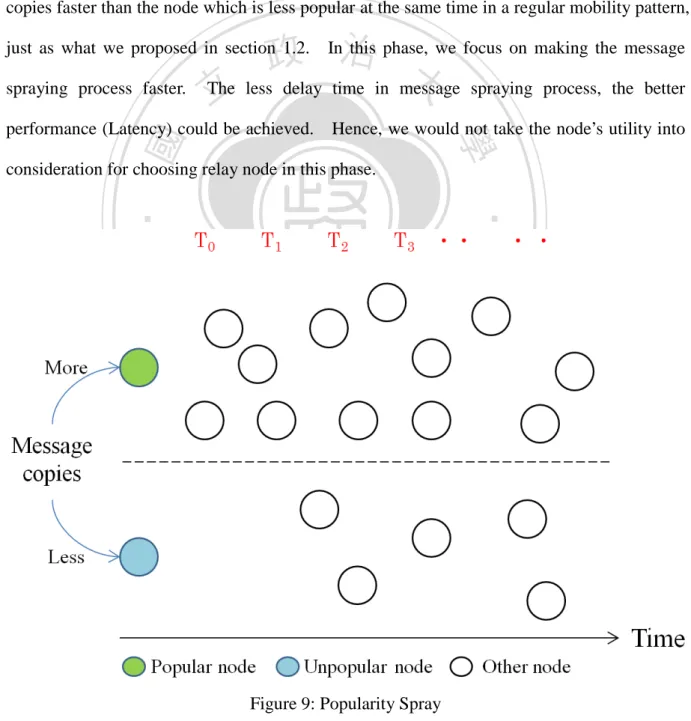
(29) in last period of time. The spraying formula could be modified to � for the sender and �. (Remains of 𝑁𝑁) ∗ CC j CC i + CC j. (Remains of 𝑁𝑁)∗ CC i CC i + CC j. � copies. � copies for the receiver, where CCi and CCj represent the. contact counts of nodei (sender) and nodej (receiver) in last period of time, respectively.. The core concept in Popularity Spray is to let a node which was more popular in the past keep more message copies to spray.. By way of this approach, it could spray these message. copies faster than the node which is less popular at the same time in a regular mobility pattern, this phase, we focus on making the message 政 In治 大 The less delay time in message spraying process, the better 立. just as what we proposed in section 1.2. spraying process faster.. ‧ 國. Hence, we would not take the node’s utility into. 學. performance (Latency) could be achieved.. consideration for choosing relay node in this phase.. ‧. n. er. io. sit. y. Nat. al. Ch. engchi. i n U. Figure 9: Popularity Spray 18. v.
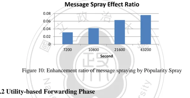
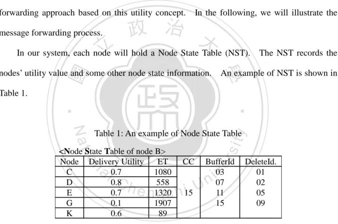
(30) We illustrate this idea in Figure 9, as we can see, based on a predictable inference, if we give a popular node more message copies than an unpopular node to spray, the message copies will be sprayed more fast.. Based on our mobility scenario, we also further examine. the message spraying effect compared with Binary Spraying. In the simulation time of 12 hours, we can get almost 8% enhancement ratio of message spraying as shown in Figure 10.. Message Spray Effect Ratio 0.08 0.06. 立. 0.04 0.02. 政 治 大. ‧ 國. 7200. 10800. 21600. 學. 0. 43200. Second. ‧. Figure 10: Enhancement ratio of message spraying by Popularity Spray. sit. y. Nat. io. er. 3.2 Utility-based Forwarding Phase. al. v i n will be switched to utility-basedCforwarding U means each of the N nodes that h e n g phase, c h i which n. If a message could not be delivered to its destination during the spraying process, the message. have the message copy would stop replicating the message to other nodes unconditionally, but a directional way to guide to its destination.. The designing philosophy in this part is to let. the messages which are not successfully delivered have the chances to be further forwarded to the nodes which have a higher delivery utility (weighted value) to the messages’ destinations. Through the utility guidance instead of blind flooding messages to other nodes, we can decrease the delivery overhead while increasing the throughput of message delivery. Therefore, how to design a proper utility function in this phase is our main work. Based on our knowledge, there are four utility functions including contact frequency, contact 19.
(31) duration, encounter aging and location, which have been commonly used in many studies [8, 10, 14-18, 20], guide the message to be forwarded to its destination or to drop it.. Because. the GPS is not considered to be used for an auxiliary tool in our scenario, the location and moving speed related information are unknown, they will not to be included in our approach. Because the utility of contact duration has been proved to have a higher accuracy than the utility of contact frequency by Ze Li et al. [15], we will design a more efficient message forwarding approach based on this utility concept. message forwarding process.. 立. In the following, we will illustrate the. 政 治 大. In our system, each node will hold a Node State Table (NST).. ‧ 國. 學. nodes’ utility value and some other node state information.. An example of NST is shown in. y. ‧. io. <Node State Table of node B> Node Delivery Utility ET C 0.7 1080 D 0.8 558 E 0.7 1320 G 0.1 1907 K 0.6 89. n. al. Ch. sit. Nat. Table 1: An example of Node State Table CC. er. Table 1.. The NST records the. BufferId 03 07 11 15. n U i e n g c h 15. iv. DeleteId. 01 02 05 09. In Table 1, the NST records each node that node B has contacted.. The corresponding. Delivery Utility means the ratio of how possible the node could be contacted by node B. The Elapsed Time (ET) means the time elapsed since the last time the node contacted.. The. Contact Counts (CC) means the number of node B contacted in last period of time.. The. BufferId records the unique IDs of messages that the node currently holds. The DeleteId records the message IDs which have been successfully delivered to the destinations. 20.
(32) The calculation of Delivery Utility is as following steps: DU(i,j) =. 𝐶𝐶𝐶𝐶 (𝑖𝑖,𝑗𝑗 ). (2). 𝑇𝑇. � DU (i,j) = DU(i,k) ∗ DU(k,j). (3). � Final: DU(i,j) = Max(DU(i,j) , max (DU (i,j) )) 𝑘𝑘∈𝑁𝑁. (4). Formula (2) shows that the calculation of direct contact delivery utility between node(i) and node(j), where CD(i,j) indicates the total contact duration in a period of time, and T indicates the period of time we predefined.. 立. Here T equals 治 to 1 hour. 政 大. Formula (3) shows that the. calculation of indirect contact delivery utility between node(i) and node(j), it means node(i) and. ‧ 國. 學. node(j) could indirectly contact through another node, also called transitive property by [8]. Formula (4) shows that the final delivery utility is determined by choosing the highest utility The delivery utility will be. y. In order to make the delivery utility. sit. Nat. periodically (every time period T) updated by nodes.. ‧. from direct contact utility and all other indirect contact utilities.. io. al. er. more accurate at reflecting the network situation, we will take both old utility and new utility. v i n CDUh(i,j) = αDU(i,j)new U+ (1 − α)DU(i,j)old engchi. n. into consideration in every updated period shown in formula (5).. Where α is used to represent the network state. and α equals to. CC new. CC new +CC old. .. 21. (5). We use the contact counts to evaluate α,.
(33) Figure 11: An example of message forwarding. 學. ‧ 國. 立. 政 治 大. ‧. Whenever two nodes contact each other, they first exchange the NST.. By consulting. the NST, a node knows which messages have a better delivery performance if they are carried. y. Nat. er. io. sit. by the contact node and will be chosen to be further forwarded as shown in Figure 11. Node(A) knows message_08 has a better delivery performance by node(B), and node(B) knows. n. al. Ch. i n U. v. currently there is no message better than message delivered by node(A).. engchi. An important factor that makes the utility-based or prediction-based routing protocol work is the repeated characteristic of node moving pattern.. Therefore, we conduct an. experiment to examine the “repeated” feature in our scenario as shown in Figure 12.. 22.
(34) Average Moving Correlation 0.95 0.9 0.85. Avg Min. 0.8. Max 0.75 100. 200. 300. 政 治 大 Number of Nodes. 立. Figure 12: Average moving correlation of node moving pattern.. ‧ 國. 學. In Figure 12, it shows that the average, maximum, minimum moving correlation in our. ‧. proposed scenario for three groups of node densities, respectively.. sit. y. Nat. Where moving correlationi :. n. al. er. io. Counts of both_contact_nodes + both_uncontact_nodes for nodei in two consecutive periods of time Total number of nodes − 1. i n U. Ch. v. e n g cScheduling hi 3.3 Message Forwarding with Priority Phase In DTNs, the contacts among nodes may not last a long time, but very short and unstable due to node mobility and the protocol used in physical layer.. At every contact, a node probably. does not have enough time to deliver all the selected messages to the contact node. Moreover, carry-and-forward is an important characteristic in DTNs.. Hence, the message. delivery sequence could directly affect the successful message delivery ratio.. Therefore, we. propose an approach to schedule the message forwarding sequence according to the cost to the destination along with a contention mechanism based on message priority. In our protocol, we divide messages into four priorities. 23. A message will be.
(35) automatically assigned to a priority when it is created, and all the other copies of this message will remain the same priority.. The concern in this part is that we wish to take both the. message priority and the cost to its destination into consideration, making it possible to have a differential delivery performance for different message priorities in DTNs.. As mentioned in. section 2.3.1, we use the elapsed time since the destination last met as the cost for a node delivering message to the contact node.. The longer the time elapsed indicates the more. distance between the source and the destination.. If delivering a message which has a longer. 政 治 大. elapsed time for the contact node, it will still be difficult for the contact node to deliver the. 立. message to its destination. Therefore, the basic concept is the shorter the elapsed time that a. ‧ 國. 學. message has for the contact node, the more advance that a message could be transmitted to it. Besides, in order to achieve a differential performance among the four priorities of messages. ‧. and avoid the transmission opportunity over centralizing on a higher priority message, we. y. Nat. n. al. Basically, there are four Access Categories for. er. io. sort the message forwarding sequence.. sit. apply the contention mechanism derived from the backoff time of EDCA in IEEE 802.11e to. i n U. v. different data packets in EDCA, and each one has different range of backoff time which. Ch. engchi. indicates a waiting time for accessing the medium.. We use this concept to make different. priorities of messages have corresponding sorting weight, an example of this phase is illustrated in Figure 13.. 24.
(36) 立. 政 治 大. ‧. ‧ 國. 學. Figure 13: An example of calculating message forwarding sequence. For simplicity, we demonstrate message forwarding process for one message in Figure. sit. y. Nat. 11, but in a realistic situation there are probably many messages selected to be forwarded.. io. al. v i n C husing message’sUET multiplied priority, engchi. The sequence for delivering is calculated by considering message’s Cost. n. utility by node(B).. er. Therefore, in Figure 13, there are five messages (red color) which have a better delivery. and Weight Range of its. randomly chosen from its Weight Range.. by a weighted value. After getting the FS value of all messages, we sort. them increasingly. The smaller the FS value, the earlier the corresponding message can be sent. Note that because a message may be in Spray Phase or Forwarding Phase, in the whole delivery process, a newly created message will be sprayed to distinct N nodes first.. Hence,. the messages in the Spray Phase are always sent before the messages in the Forwarding Phase shown in Figure 14.. 25.
(37) Figure 14: Message transmission queue. 治 政 大 3.4 Buffer Management Strategy 立 In section 3.1, 3.2 and 3.3, we focus on the delivery strategy of the message. ‧ 國. 學. remember that the store-carry-and-forward is a basic message delivery concept.. So far we. Because delivering a message in DTNs relies on a. ‧. have only discussed the “forward” part.. However,. node, which carries it to the destination, the message would be temporary stored in the node. y. Nat. io. sit. Hence, a node’s storage space (Buffer) becomes another important factor that would. er. buffer.. affect the delivery performance.. n. al. Ch. i n U. v. If the buffer is unlimited, Epidemic would be the most efficient routing protocol and the easiest way to implement. environments.. engchi. Yet it is probably impossible in reality, especially in some severe. Thus, we assume that the buffer size is limited, and there should be an. efficient method for the management of the buffer. Traditionally, when the buffer is full, but the incoming message wanting to be stored, the node would drop the message which has the longest receiving time or the lowest TTL for receiving the newly incoming message. In order to utilize buffer more efficiently, we propose a buffer management strategy to allocate the storage resource to different messages.. 26. Because the longer a message remained.
(38) in the buffer, the more chances the message could be further sent, we should design some criteria to decide which message has a higher priority to use the buffer resource, and which message could be dropped first when buffer is full.. In the former sections, we introduced the. delivery process of a message, including the Spray Phase and the Forwarding Phase. Messages play different roles in each phase, and we assign the priority of using buffer resource according to the nature of the role.. Because Spray Phase is the first step for the. message delivery process, it is fundamental to Forwarding Phase.. 政 治 大. Hence, the message in. Spray Phase would have a highest priority to use the buffer resource.. 立. When a message. switched into Forwarding Phase, we use the comparison of messages’ utilities to make the. ‧ 國. 學. message with a higher utility can use the buffer resource with a higher priority. resource allocation algorithm is shown in Figure 15.. ‧. n. er. io. sit. y. Nat. al. Ch. engchi. i n U. v. Figure 15: Buffer management strategy 27. The buffer.
(39) As shown in Figure 15, when a node receives a message which is still in the Spray Phase, the node will drop a message which has the lowest utility from the lowest to the highest message priority except the message which is still in the Spray Phase.. The process of. dropping message will continue until the buffer is big enough to save the incoming message. If all the messages in the buffer are in Spray Phase, the node will reject the incoming message. On the other hand, if the incoming message is in the Forwarding Phase, the node will drop a message which has the lowest and a lower utility than the incoming message’s utility from the. 治the dropping process will continue until the 政As well, 大. lowest to the highest message priority.. 立. buffer is big enough to save the incoming message.. However, if all the messages’ utilities. ‧ 國. 學. are higher than the incoming message’s utility, the node will reject the incoming message. Through this buffer management strategy based on message’s utility and different message. ‧. priorities, it could be better than the management based on the message’s TTL or receiving. sit. y. Nat. time.. n. al. er. io. Note that in Table 1, there is a column called “DeleteId”.. i n U. v. This column will record the. IDs of messages that have been successful delivered to their destinations.. Ch. engchi. Whenever nodes. exchange their NSTs, one side will then update the “DeleteId” column in itself NST by consulting the other side’s NST, and each side will first delete the message which ID is in the “DeleteId” column before attempting to transmit the message.. 28.
(40) CHAPTER 4 Simulation and Results. 政 治 大 compares it with some representative routing algorithms. 立. In this chapter, we will analyze the performance of our proposed scheme by simulation, and. ‧ 國. 學. 4.1 Performance Metrics. ‧. The challenge in DTNs is to make communication possible and efficient among nodes under a. sit. y. Nat. situation of end to end path does not stably exist from the source to the destination. Hence,. io. al. er. an optimal algorithm should route message with maximizing the successful delivery ratio. v ni. n. while minimizing the delivery delay and the overhead ratio.. Ch. engchi U. as the indicators of routing performance as follows:. We will take these three metrics. 1. Delivery ratio (Successful delivery ratio from the source to the destination) 2. Overhead ratio (. Relayed messages −Successful Delivered messages Successful Delivered messages. ). 3. Delivery delay (Latency of successful delivery). Furthermore, we take the performance of our proposed scheme (called SFMS in the simulation charts) in comparison with other four representative algorithms, which are Epidemic [5], Spray and Wait [7], PROPHET [8], and UDM [14].. 29.
(41) 4.2 Simulation Setup We choose the ONE (Opportunistic Network Environment) [21] simulator (version 1.4.1) to be the tool for simulation.. The ONE provides a map-based model of a real city (Helsinki),. and that could be suitable for our scenario.. The specific focus for DTNs related MANET. simulations [22] is another reason that we choose it.. Figure 16 shows a snap shot of the. ONE simulator.. 立. 政 治 大. ‧. ‧ 國. 學. n. er. io. sit. y. Nat. al. Ch. engchi. i n U. v. Figure 16: A snap shot of the ONE simulator. 30.
(42) 4.2.1 Simulation Settings In our scenario, we have three kinds of nodes, pedestrians, cars, buses, respectively. Pedestrians will randomly choose positions (destinations) based on the map and begin to moving to them with the mobility pattern that we described in section 1.2. Because the pedestrians move not so fast, and the node distribution may be very sparse, we add the property of cars and buses to make the flow of messages more efficient. Cars and buses have the same mobility pattern with pedestrians, but cars and buses will have a faster moving speed and fixed buffer size.. 政 治 大. The destination of a message is one of the pedestrians, and there are four messages (four. 立. The other parameters are described in Table 2.. 學 ‧. Table 2: Parameters of simulation setting. Nat. Helsinki. Map Size. 4500m × 3400m. io. sit. y. Map. Simulation Time. 43200 Sec. Warm-up Time. 1000 Sec. n. al. Ch. Transmission Rate. er. pedestrians.. ‧ 國. priorities of message respectively) which will be periodically created by four of the. i n U. v. e n g c750KBps h i (Pedestrians、Cars) 10Mbps (Buses). Transmission Range. 10m (Pedestrians、Cars) 100m (Buses). Node Speed. 2.8 ~ 6.4 km/h (Pedestrians) 28.8 ~ 43.2 km/h (Cars) 18 ~ 36 km/h (Buses). Buffer Size. 5MB – 100MB (Pedestrians) 50MB (Cars、Buses). Message Size. 500KB ~ 1MB. Interval of Message Creation 30 – 50 Sec Time To Live. 18000 Sec 31.
(43) 4.3 Simulation Results In order to show the effect of our algorithm, we will evaluate our scheme in two aspects: Different buffer sizes and Different node densities, and compare with the other four algorithms described in section 4.1.. 4.3.1 Performance of Different Buffer Sizes First, we show the delivery ratio, overhead ratio and delivery delay on average in Figure 17, Figure 18 and Figure 19.. Delivery Ratio. ‧ sit. io. 0.4. y. Nat. 0.5. n. al. er. 0.6. 學. 0.7. ‧ 國. 立. 政 治 大. 0.3 0.2. Ch. engchi. i n U. v. 0.1 0 5. 25. 50. 100. Buffer Size (MB) Epidemic. SAW. Prophet. UDM. Figure 17: Delivery ratio vs. Different buffer sizes. 32. SFMS.
(44) Overhead Ratio 70 60 50 40 30 20 10 0. 立 Epidemic. 25. 50. 100. Buffer Size (MB) SAW. 學. ‧ 國. 5. 政 治 大 Prophet. UDM. SFMS. ‧. Figure 18: Overhead ratio vs. Different buffer sizes. sit. Delivery Delay. n. al. er. io. 10000. y. Nat Sec. 9000 8000. Ch. engchi. i n U. v. 7000 6000 5000 4000 3000 5. 25. 50. 100. Buffer Size (MB) Epidemic. SAW. Prophet. UDM. SFMS. Figure 19: Delivery delay vs. Different buffer sizes 33.
(45) As we can see in Figure 17, Figure 18 and Figure 19, our SFMS algorithm has a better delivery ratio among all the compared algorithms while maintaining a very low overhead ratio. Epidemic suffers from huge redundant message copies.. It would also cause too many. messages be dropped so that the messages could not efficiently be carried to their destinations. Hence, Epidemic has a maximum overhead ratio and the worst delivery ratio.. Because. PROPHET updates the utility every node contact, the accuracy of the result is not good enough to be a good forwarding indicator, especially in our simulation scenario.. 政 治 大. Hence,. PROPHET still suffers from heavily overhead ratio, and causes a worse message delivery. 立. Spray And Wait has a medium delivery ratio performance and the lowest overhead. 學. ‧ 國. ratio.. ratio, because it restricts the number of a message that could be copied to other nodes. could control the overhead in a very low ratio.. UDM has a similar routing step and forwarding strategy. y. Nat. Hence, it has almost the same low overhead ratio with SFMS. But in SFMS,. sit. with SFMS.. Yet on the other hand, it also restricts the. ‧. potential delivery performance.. It. n. al. er. io. we adopt a popularity spray strategy that could perform more efficiently the distribution of the. i n U. v. N message copies, and in the forwarding process we import the aging of contact to more. Ch. engchi. precisely guide the transmission sequence. Therefore, SFMS could achieve a better delivery ratio than UDM through all the buffer sizes in the simulation.. Note that comparing with. UDM, SFMS has a better performance of delivery ratio that is more obvious in the condition of the small buffer size, but slightly better than UDM in the condition of the big buffer size. The reason is that the bigger buffer size could store more messages, and the chances for the messages to be dropped would also become smaller.. Because the messages could be carried. longer in the process of delivering due to the bugger buffer size, the effect of our proposed method may not benefit the delivery performance that much.. In other words, the advantage. of SFMS may be covered when the resource (buffer) become more and more sufficient. 34.
(46) However, the buffer size could be bigger, and so does the size of message such as high definition images or video segments.. Therefore, making the focus on the condition of the. low buffer size would reflect the delivery performance more reasonably under considering both buffer size and message size. In the performance of the delivery delay, SFMS and UDM have a medium performance. Epidemic and PROPHET suffer from the defect of heavily overhead ratio, so that the successful message delivery may take a longer time to achieve.. 政 治 大. However, Spray and Wait. has a medium delivery ratio and lowest overhead ratio, it takes the “Drop Oldest” method in. 立. the buffer management.. When the buffer size is not big enough to receive the incoming. ‧ 國. 學. message, it will drop the message which has the longest receiving time.. Hence, the. successfully delivered messages would have a lower delivery delay.. ‧. Furthermore, in SFMS, we propose a message scheduling approach to provide a. y. Nat. Figure 20, Figure 21,. sit. differential delivery performance for different priorities of messages.. n. al. er. io. Figure 22 and Figure 23 will show the results of the effect of our approach.. Ch. i n U. v. e n g c h iRatio Delivery. 0.6 0.5 0.4 0.3 0.2 0.1 0 1. 2. 3. 4. Message Priority Epidemic. SAW. Prophet. UDM. SFMS. Figure 20: Delivery ratio vs. Individual message priority of 5MB buffer 35.
(47) Delivery Ratio 0.7 0.6 0.5 0.4 0.3 0.2 0.1 0 1. 2. 3. 4. Message Priority. Epidemic. 立. 政 治 大 SAW. Prophet. UDM. SFMS. ‧ 國. y. sit er. al. n. 0.5. io. 0.6. ‧. 0.7. Delivery Ratio. Nat. 0.8. 學. Figure 21: Delivery ratio vs. Individual message priority of 25MB buffer. 0.4 0.3 0.2 1. Ch. engchi. i n U. 2. v. 3. 4. Message Priority Epidemic. SAW. Prophet. UDM. SFMS. Figure 22: Delivery ratio vs. Individual message priority of 50MB buffer. 36.
(48) Delivery Ratio 0.8 0.7 0.6 0.5 0.4 0.3 0.2 1. 2. 3. 4. Message Priority. Epidemic. 立. 政 治 大 SAW. Prophet. UDM. SFMS. ‧. ‧ 國. 學. Figure 23: Delivery ratio vs. Individual message priority of 100MB buffer. In Figure 20, Figure 21, Figure 22 and Figure 23, we can observe that in the performance of. sit. y. Nat. delivery ratio, Epidemic, PROPHET, and Spray and Wait almost have no different among the four. io. er. message priorities (Note that the message priority 1 indicates the highest priority, and message. al. v i n Ch and make no different delivery performance U e n gamong c h i messages. n. priority 4 indicates the lowest priority), because they take all the messages as the same priority, SFMS and UDM provide the. concept of different message priorities, some scenarios such as military areas or credit-based applications may need a differential service for different priorities of messages. SFMS could achieve a better delivery ratio in all the scenarios of buffer size, especially in a lower buffer size condition. SFMS obviously enhances the delivery ratio of the high priority messages (priority 1 and 2), but it still maintain an acceptable (at least an average performance that compared with another four algorithms) delivery ratio on the lower priority messages (priority 3 and 4). We also analyze the delivery delay in different priorities of message shown in Figure 24, Figure 25, Figure 26 and Figure 27. 37.
(49) Delivery Delay. Sec 7000 6500 6000 5500 5000 4500 4000. 立 Epidemic. 2. 3. 4. Message Priority SAW. 學. ‧ 國. 1. 政 治 大 Prophet. UDM. SFMS. ‧. Figure 24: Delivery delay vs. Individual message priority of 5MB buffer. 6500 6000. sit. y. n. al. er. Delivery Delay. io. 7000. Nat. Sec 7500. Ch. engchi. i n U. v. 5500 5000 4500 4000 1. 2. 3. 4. Message Priority Epidemic. SAW. Prophet. UDM. SFMS. Figure 25: Delivery delay vs. Individual message priority of 25MB buffer. 38.
(50) Delivery Delay. Sec 9500 9000 8500 8000 7500 7000 6500 6000 5500 5000. 立. Epidemic. 2. 3. 4. Message Priority SAW. 學. ‧ 國. 1. 政 治 大 Prophet. UDM. SFMS. ‧. Figure 26: Delivery delay vs. Individual message priority of 50MB buffer. sit. Deliver Delay. n. al. er. io. 9000. y. Nat Sec 9500. 8500. Ch. engchi. i n U. v. 8000 7500 7000 6500 6000 5500 1. 2. 3. 4. Message Priority Epidemic. SAW. Prophet. UDM. SFMS. Figure 27: Delivery delay vs. Individual message priority of 100MB buffer 39.
(51) As we can observe, Spray and Wait, Epidemic and PROPHET have a shorter delivery delay in a smaller buffer size shown in Figure 24.. Because the three algorithms perform a. strategy of dropping message with oldest receiving time when the buffer is full, the condition of dropping message would frequently happen in a smaller buffer size.. It would frequently. cause that the message to be replaced by which with a shorter receiving time, that makes the average message delivery delay smaller. As the buffer size becomes bigger as shown in Figure 25, Figure 26 and Figure 27,. 政 治 大. SFMS gradually outperforms the other algorithms and still maintain a differential. 立. performance among the four priorities of messages.. Because when the buffer size becomes. ‧ 國. 學. bigger, the other four algorithms would have bigger space to store more messages, and that would cause the average delivery delay longer.. In other words, the message replaced by the. ‧. one with a shorter receiving time would become less frequent.. n. er. io. al. sit. y. Nat. 4.3.2 Performance of Different Node Densities. i n U. v. We also analyze the effect of performance over different node densities.. Ch. engchi. In DTNs, the. delivery of message is based on the intermittent connection among nodes. Hence, if the number of the node increases, the chances of contacting a node would also increase theoretically. increase.. In other words, the chances that a message is carried by another node would. Because the increasingly chances of message relay, it needs an appropriate. approach to choose the relay node, otherwise the delivery of message may become more and more inefficient.. Therefore, in this section, we will analyze the five algorithms’ message. delivery performance over different node densities. The performance results are shown in Figure 28, Figure 29 and Figure 30.. 40.
(52) Delivery Ratio 0.75 0.7 0.65 0.6 0.55 0.5 0.45 0.4 0.35 100. 150. 200. 政 治 大. Number of nodes (Density). 立. Epidemic. SAW. Prophet. UDM. SFMS. ‧ 國. 學. Figure 28: Delivery ratio vs. Different node densities. ‧ y. sit er. al. n. 80. io. 100. Nat. 120. Overhead Ratio. 60 40. Ch. engchi. i n U. v. 20 0 100. 150. 200. Number of Nodes (Density) Epidemic. SAW. Prophet. UDM. SFMS. Figure 29: Overhead ratio vs. Different node densities. 41.
(53) Delivery Delay. Sec 9500 9000 8500 8000 7500 7000 6500 6000 5500 100. 150. 政 治 大. 200. Number of Nodes (Density). 立. Epidemic. SAW. Prophet. UDM. SFMS. ‧ 國. 學. Figure 30: Delivery delay vs. Different node densities. ‧. io. enhancement in comparison with UDM.. SFMS still control the overhead ratio well.. n. al. sit. Hence, the average delivery ratio of SFMS has a slightly. er. Nat. delivery utility increase as well.. y. Because the number of the node increases, the chances of contacting a node with a better. i n U. v. Moreover, the performance of delivery delay has a positive reflection as well.. Ch. engchi. Because the. strict restriction of message copies in Spray and Wait, it would not benefit from the increasing number of the node.. Because Epidemic and PROPHET do not have a strict restriction on. message copies, they could have a slightly enhancement on delivery ratio due to the widely increasing chances of delivering a message to another one.. However, they will cause a. direct proportion increasing to the overhead ratio. In the end of this section, we will analyze the contention mechanism applied to SFMS in Figure 31 and Figure 32.. The core concept of this mechanism is to let lower priority of. message have a chance to contend with higher priority of message to acquire an earlier forwarding sequence. 42.
(54) Gap of Delivery Ratio 0.2 0.15 0.1 0.05 0 100. 150. 200. 300. Number of Nodes (Density). 政 治 大 UDM. 立. SFMS. y. sit. al. n. 6. io. 8. er. 10. Gap of Overhead Ratio. Nat. 12. ‧. ‧ 國. 學. Figure 31: Delivery ratio gap vs. Different node densities. 4 2. Ch. engchi. i n U. v. 0 100. 150. 200. 300. Number of Nodes (Density) UDM. SFMS. Figure 32: Overhead ratio gap vs. Different node densities. Due to the increasing chances of the node contact, a node would have more chances to forward a message to another node.. It also indicates that the lower priority the message has,. 43.
(55) the more chances to contend the forwarding sequence.. This is very different from UDM,. which has a fixed transmission sequence for different priorities of messages.. In Figure 31,. we can observe that SFMS has a smaller gap between the highest message priority and the lowest message priority when the number of node increases, and the same also happened in the gap of overhead ratio shown in Figure 32.. 立. 政 治 大. ‧. ‧ 國. 學. n. er. io. sit. y. Nat. al. Ch. engchi. 44. i n U. v.
(56) CHAPTER 5 Conclusions and Future Work. 政 治 大 They are popularity spray phase, utility-based forwarding phase, and message 立. In this thesis, we propose a three-phase routing protocol for a message in the process of delivery.. ‧ 國. Firstly, popularity spray mechanism could distribute. 學. delivery sequence phase, respectively.. message to distinct N nodes more efficiently in a regular node mobility pattern than source. ‧. spraying and binary spraying.. Secondly, utility-based forwarding mechanism could consult. sit. y. Nat. the history of contact duration to further forward the message to another node with multi-copy. io. al. v i n C h which is readyUto be every message engchi. Thirdly, before actually transmitting the messages to the contact. n. popularity spray phase. node, SFMS will let. er. to enhance the delivery performance when a message can not find its destination in the. sent contend the forwarding. sequence according to their priorities and costs that defined as the time aging from last contact of the destination.. Through this scheduling mechanism, SFMS can not only forward. message more accurate but also maintain a better resource allocation for all priorities of messages. For further research, the calculation of predicting contact popularity and contact utility would be a topic that is worth to study. It is expected to be more accurate to reflect the future node state such as taking node moving speed into consideration and evaluates the effectiveness between popularity and hop counts for further adjusting the message spraying strategy. 45.
(57) REFERENCES. [1] J. Shen, S. Moh, I. Chung, “Routing Protocols in Delay Tolerant Networks: A Comparative Survey,” In ITC-CSCC, Chosun University, Korea, July 2008.. 政 治 大. [2] E.P.C. Jones, P.A.S. Ward, “Routing Strategies for Delay-Tolerant Networks,” Submitted to Computer Communication Review, University of Waterloo, Canada, 2008. 立. ‧. ‧ 國. 學. [3] R.H. Frenkiel, B.R. Badrinath, J. Borras, R.D. Yates, “The Infostations Challenge: Balancing Cost and Ubiquity in Delivering Wireless Data,” In IEEE Personal Communications, vol. 7, no. 2, pp. 66-71, April 2000.. n. al. er. io. sit. y. Nat. [4] L. Pelusi, A. Passarella, M. Conti, IIT-CNR, “Opportunistic Networking: Data Forwarding in Disconnected mobile ad hoc networks,” In IEEE Communications Magazine, Vol. 44, no. 11, pp. 134-141, November 2006.. i n U. v. [5] A. Vahdat and D. Becher, “Epidemic Routing for Partially-Connected Ad Hoc networks,” In Technical Report CS-2000-06, Duke University, July 2000.. Ch. engchi. [6] A. Demers, D. Greene, C. Houser, W. Irish, J. Larson, S. Shenker, H. Sturgis, D. Swinehart, and D. Terry, “Epidemic Algorithms for Replicated Database Maintenance,” In SIGOPS Operating Systems Review, vol. 22, pp. 8-32, January 1988. [7] T. Spyropoulos, K. Psounis, C.S. Raqhavendra, “Spray and Wait: An Efficient Routing Scheme for Intermittently Connected Mobile Networks,” In Proc. SIGCOMM, EE, USC, USA, August 2005. [8] A. Lindgren, A. Doria, and O. Schel’en, “Probabilistic Routing in Intermittently Connected Networks,” In Proc. SIGMOBILE, vol. 7-3, LUT, Sweden, July 2003.. 46.
(58) [9] J. LeBrun, C.N. Chuah, D. Ghosal, M. Zhang, “Knowledge-Based Opportunistic Forwarding in Vehicular Wireless Ad Hoc Networks,” In Proceedings of IEEE Vehicular Technology Conference (VTC), vol. 4, pp. 2289-2293, University of California, Davis, USA, May 2005. [10] T. Umedu, H. Urabe, J. Tsukamoto, K. Sato, T. Higashino, “A MANET Protocol for Information Gathering from Disaster Victims,” In PERCOMW, Osaka University, Japan, March 2006. [11] X. Pallot, L.E. Miller, “IMPLEMENTING MESSAGE PRIORITY POLICIES OVER AN 802.11 BASED MOBILE AD HOC NETWORK,” In MILCOM, NIST, USA, 2001.. 立. 政 治 大. ‧ 國. 學. [12] C. Suthaputchakun, A. Ganz, “Military Inter-Vehicle Communication with Message Priority using IEEE 802.11e,” In MILCOM, University of Massachusetts Amherst, USA, October 2006.. ‧. [13] H. Gong, J.W. Kim, “A Prioritization-Based Application-Oriented Broadcast Protocol for Delay-Tolerant Networks,” In WCNC, GIST, Korea, 2009.. sit. y. Nat. er. io. [14] Z. Li, H. Shen, “Utility-based Distributed Routing in Intermittently Connected Networks,” In ICPP, University of Arkansas, USA, September 2008.. al. n. v i n CExploiting [15] Z. Li, H. Shen, “SEDUM: Networks in Utility-Based Distributed U h e n g cSocial i h Routing for DTNs,” In IEEE Transactions on Computers, Vol. 62, no 1, pp. 83-97, Clemson University, USA, January 2013. [16] H. Dubois-Ferriere, M. Grossglauser, M. Vetterli, “Age Matters: Efficient Route Discovery in Mobile Ad Hoc Networks Using Encounter Ages,” In MobiHoc, EPFL, Switzerland, June 2003. [17] I. Joe, K. Sang-Bo, “A Message Priority Routing Protocol for Delay Tolerant Networks (DTN) in Disaster Areas,” In FGIT, Hanyang University, Korea, December 2010.. 47.
數據

![Figure 2: Selection of message priority [17].](https://thumb-ap.123doks.com/thumbv2/9libinfo/8332251.175520/21.892.166.783.341.800/figure-selection-of-message-priority.webp)
![Figure 3: Area covered by route discovery floods [16].](https://thumb-ap.123doks.com/thumbv2/9libinfo/8332251.175520/22.892.223.684.376.833/figure-area-covered-route-discovery-floods.webp)
+7
![Figure 5: Priority queuing approach [11]](https://thumb-ap.123doks.com/thumbv2/9libinfo/8332251.175520/24.892.450.812.970.1093/figure-priority-queuing-approach.webp)
![Figure 7: Prioritized backoff time distribution mechanism [11]](https://thumb-ap.123doks.com/thumbv2/9libinfo/8332251.175520/25.892.128.807.170.871/figure-prioritized-backoff-time-distribution-mechanism.webp)
相關文件
2.8 The principles for short-term change are building on the strengths of teachers and schools to develop incremental change, and enhancing interactive collaboration to
Robinson Crusoe is an Englishman from the 1) t_______ of York in the seventeenth century, the youngest son of a merchant of German origin. This trip is financially successful,
fostering independent application of reading strategies Strategy 7: Provide opportunities for students to track, reflect on, and share their learning progress (destination). •
3.16 Career-oriented studies provide courses alongside other school subjects and learning experiences in the senior secondary curriculum. They have been included in the
Students are asked to collect information (including materials from books, pamphlet from Environmental Protection Department...etc.) of the possible effects of pollution on our
• Definition: A max tree is a tree in which the key v alue in each node is no smaller (larger) than the k ey values in its children (if any). • Definition: A max heap is a
Binding Warning message Binding Update message AAAO: the AAA server of the old foreign network to which the OFA belongs. AAAF: the AAA server of the new foreign network to which the
Start with a STUN header, followed by a STUN payload (which is a series of STUN attributes depending on the message type).
