國
立
交
通
大
學
資訊學院 資訊學程
碩
士
論
文
Integrating BT of Broadcom with MTK handset platform
研 究 生:郭永輝
指導教授:張瑞川 教授
Integrating BT of Broadcom with MTK handset platform
研 究 生:郭永輝 Student:Yu-Hui Kuo
指導教授:張瑞川 Advisor:R.C. Chang
國 立 交 通 大 學
資訊學院 資訊學程
碩 士 論 文
A Thesis
Submitted to College of Computer Science
National Chiao Tung University
in partial Fulfillment of the Requirements
for the Degree of
Master
in
Computer and Information Science
December 2006
整合博通藍芽晶片於聯發科手機晶片
學生: 郭 永 輝 指導教授:張 瑞 川
國 立 交 通 大 學 資 訊 學 院 資 訊 學 程 碩 士 班
Abstract(Chinese)
本論文研究的動機是因為我們希望能在聯發科的
6217 平台上支援更多藍
芽
Profiles. 這原因乃是因為聯發科 6217 晶片只支援耳機 Profile. 所以,我們
希望在現有
MTK 軟體平台上,整合博通藍芽產品 2045 晶片,來支援多達四種
Profiles (耳機, 檔案傳輸, 序向埠與物件推擠).
為此,我們採用 Bottom-Up 的方法來將博通的藍芽 2045 晶片整合至現有
手機軟體上.
z 將藍芽協定的中介層(GKI)原有對作業系統的介面程式導向到聯發科
的中介層(KAL).這些介面程式包含有精準系統時間(tick)的改變,取得
工作辨別碼(Task ID),系統等待(wait),系統延遲(Delay),觸發事件
(send event), 啟動計時器 (Start Timer) 及停止計時器等.
z 建立新的軟體模組(BTM)在既有手機協定層,負責對上與人機介面層
溝通,對下與藍芽協定層溝通.相對於這新的軟體模組,我們也須於各介
面層之間,同時建造新的訊息對(message request and message
response)以便串接上下流的溝通.
z 將藍芽協定的除錯訊息,導向到聯發科的 PC 除錯程式(catcher)中,方
便讓我們在進行軟體整合中,來除錯程式.這些蟲(Bug)包含了訊息對
的內容出錯,及不正常當機情形.
z 設計出適合客戶需求的藍芽人機介面操作流程(scenario).
我們將我們的實作手機(i-Mobile TV901)與 Sony-Ericsson
S700,Motorola V3 來做 FTP client and server 效能評估.我們發現,我們的
手機在
FTP client 測項上,表現勝過 S700 與 V3.但在 FTP server 兩項測項上
(forward and get),S700 的表現勝過 TV901. 而 V3 只在 FTP server get
測項上微幅領先 TV901, 其它測項都落後 S700 與 TV901. (Refer to section
5.3 Result).
Integrating BT of Broadcom with MTK handset platform
student:Yu-Hui Kuo
Advisors:Dr. R.C. Chang
Degree Program of Computer Science
National Chiao Tung University
Abstract(English)
The motivation of research of this thesis is that we wish to support more Bluetooth profiles in MTK 6217 handset platform. Because MTK 6217 only supports headset, hand-free profiles, we hope to integrate BT 2045 chipset of Broadcom with MTK current software in order to support for four types of profiles (HS/HF, FTP, SPP and OPP).
Based on this cause, we adopt the bottom-up way to integrate BT 2045 chipset with current handset software.
z Replacing the interface of GKI over OS with the interface of GKI over KAL. These interfaces include tick-update, get-task-id, wait, delay, send-event, start-timer and stop-timer and so on.
z Creating a new software module (BTM) located in protocol stack of handset. It interfaces up with both MMI and down with protocol stack of BT. Associating with the new software module, we need to create the new message pairs including message request and message response in each one layer.
z Directing the debug message of BT into PC debug application program (catcher) of MTK. It can let us debug the program in the integration period. These bugs include wrong contents of message and abnormal shutdown of system.
z Designing a scenario of MMI of BT to match for the requirement of customer.
We take our implemented handset (i-Mobile TV901) to compare the performances with both Sony-Ericsson S700 and Motorola V3 in FTP client and server. We found that the performance of our handset is over those of S700 and V3 in the test item of FTP client. But in the two test items (forward and get) of FTP server, the performance of S700 is over that of TV901. For V3, it is a little greater than that of TV901 in the test item of FTP server get. While, the other test items is
Acknowledgement
First, I thank my direct professor of Doctor (R.C. Chang) for his guide and direction in my thesis. At the moment of thesis modification, professor always directs me in writing and architecture placement of thesis from his available time slot. As far I know, he is a very key and busy person in Acer. Hence, I sincerely thank Doctor Chang for his guide and direction to let my thesis to reach a certain quality.
Besides, I sincerely thank two professors, Doctor Shih and Doctor Feng for acting as my oral examination professors in master degree.
During the period of four and half years in NCTU, I encounter many things that I have ever not met in my previous studying experience. For example, in studying compiler subject, I must often go aboard to test our handset for two months to result in my not passing this subject even I have tried my best. Besides, the driving in the night from Taipei to Hsinchu and Hsinchu to Taoyuan is a very impressive thing in the first three years. I think the most important factor to last me go on continuously is that my family, especially my wife (Jenny Huang).
Finally, I sincerely thank my boss (Kenneth Wu) in work for his consideration to let me be able to get the degree in working time.
Contents
Abstract(Chinese) ...3
Abstract(English) ...4
Acknowledgement ...5
Contents ...6
List of Tables...8
List of Figures ...9
1 Introduction...10
1.1 Motivation...10
1.2
The Result of Research ...10
2
The Review on Previous Work ...12
2.1 Bluetooth
System
Architecture ...12
2.1.1 Frequency
Hopping...12
2.1.2
The Master, Slave and Piconet...13
2.1.3 The
Scatternet ...14
2.1.4
The BT Protocol...15
2.1.4.1
Link Manager Protocol (LMP) ...16
2.1.4.2
Logical Link Control Adaptation Protocol (L2CAP)...17
2.1.4.2.1 Signaling ...17
2.1.4.2.2 Transmission ...18
2.1.4.2.3
L2CAP Packet Format ...19
2.1.4.2.4
The relation between L2CAP and baseband in
packet segmentation and combination ...19
2.1.4.3 RFCOMM ...22
2.1.4.4
Service Discovery Protocol (SDP)...23
2.2
Bluetooth Stack of Broadcom ...24
2.3
Mobile System Software Architecture of MTK...26
2.3.1
OS and Inter-ware Layer...26
2.3.2 Protocol
Layer...27
2.3.2.1 Layer
1 ...27
2.3.2.2 Layer
2 ...27
2.3.2.3 Layer
3 ...27
2.3.2.4 Layer
4 ...27
2.3.3 GUI
Layer ...28
3 Approaches
of
Integrating BT with MTK Platform...29
3.1 System
Service...31
3.3.1 General
Function...33
3.3.2
Relevant Profile Function ...34
3.3.2.1 HS/HF
Profile ...34
3.3.2.2 FTP
Profile ...36
3.3.2.3 SPP
Profile ...37
3.4
Sleep Mode and Hardware Flow Control ...38
4
Implementation of the New System Architecture...40
4.1 L4
Subsystem...41
4.1.1
BlueTooth Manager Module ...41
4.1.2 BTM
Function...41
4.2 BT
Subsystem ...42
4.2.1 BTA
Module...42
4.2.1.1 BTUI ...43
4.2.2 BTU
Module ...47
4.2.2.1 File
System...47
4.2.2.2 NVRAM...48
4.2.3 HCI
Module ...48
4.2.4
KAL vs. GKI (Broadcom) ...48
5
Experiment and Result...50
5.1
FTP Client Test Items...51
5.1.1
FTP Client (Forward)...51
5.1.2
FTP Client (Get)...53
5.2
FTP Server Test Items ...54
5.2.1 FTP
Server
(Forward) ...54
5.2.2 FTP
Server
(Get) ...56
5.3 Results...58
5.3.1
Discussion on the test...58
5.3.2 Improved
method ...58
6 Conclusion ...60
Reference ...61
List of Tables
Table 1: Signal of RS232 9 Pin...22
Table 2: Comparison of Throughput among TV901, V3 and S700 at FTP
Client Forward ...51
Table 3: Comparison of Throughput among TV901, V3 and S700 at FTP
Client Get ...53
Comparison of Throughput among TV901, V3 and S700 at FTP
Server Forward ...54
Table 4: Comparison of Throughput among TV901, V3 and S700 at FTP
Serve Get...56
Table 5: Summarize of Performance in FTP test items...58
List of Figures
Figure 1: Frequency Hopping ...12
Figure 2: Piconet of Bluetooth...13
Figure 3: A BT device in two piconets...14
Figure 4: Protocol stack of BT...15
Figure 5: CID of BT...17
Figure 6: Signaling and Data channel of L2CAP ...18
Figure 7: Transmission of L2CAP in Application ...18
Figure 8: Format of Packet in L2CAP ...19
Figure 9: Segment and Combination of L2CAP packet in base band ...20
Figure 10: Signal of BT ...21
Figure 11: Software Architecture of Broadcom BT...25
Figure 12: Architecture of Software of MTK ...26
Figure 13: A new architecture integrating BT with MTK...30
Figure 14: Relation between AG and HF...31
Figure 15: Software Architecture Integrating MTK and Broadcom BT...40
Figure 16: Interface among MMI, BTM and BTA ...42
Figure 17: BTA module...42
Figure 18: Message Format between BTM and BTA ...43
Figure 19: Inter Process Communication (IPC) among Broadcom BT
processes ...44
Figure 20: Integration of IPC between MTK and Broadcom ...45
Figure 21: Architecture among BTA, BTU and HCI ...47
Figure 22: Interface between HCI and Physical BT modem ...48
Figure 23: The new architecture between GKI and KAL...49
Figure 24: Comparison of Throughput among TV901, V3 and S700 at FTP
Client Forward ...52
Figure 25: Comparison of Throughput among TV901, V3 and S700 at FTP
Client Get ...53
Figure 26: Comparison of Throughput among TV901, V3 and S700 at FTP
Server Forward...55
Figure 27: Comparison of Throughput among TV901, V3 and S700 at FTP
Server Get ...57
1 Introduction
Bluetooth was designed to allow low bandwidth wireless connections to become so simple to use that they seamlessly integrate into your daily life. A simple example of a Bluetooth application is updating the phone directory of your mobile phone. Today, you would have to either manually enter the names and phone numbers of all your contacts or use a cable or IR link between your phone and your PC and start an application to synchronize the contact information. With Bluetooth, this could all happen automatically and without any user involvement as soon as the phone comes within range of the PC! Of course, you can easily see this expanding to include your calendar, to do list, memos, email, etc. This is just one of many exciting applications for this new technology!
Bluetooth Special Interest Group (SIG) formalizes the BT specification. Ericsson, IBM, Intel, Nokia and Toshiba found SIG. Since May 20,1999, SIG has had over 4000 companies to join in today.
In BT revolution, BT speed is improving from BT 1.0, 1.1, 1.2 to 2.0(+EDR). Every stage improves many software functions inside, too. We will introduce them afterwards.
1.1 Motivation
Because more handsets have the capability of short-distance wireless
connection in BT, although MTK platform has the function in 6217 but has not met our requirement in profiles and stability. And MTK next generation with improved BT cannot catch up this launch time of our product; this is why we must implement our product with Broadcom BT inside.
1.2
The Result of Research
We successfully integrate Broadcom 2045 into MTK 6217 platform between the inter-ware layers in both OS (nucleanus) and protocol of BT, the interface layer between GSM protocol and BT protocol, MMI and sleep mode. It integrates four
The rest of the thesis is organized as follows:
Chapter 2 describes the review on previous work to study Bluetooth theory, Broadcom software architecture and MTK software architecture.
Chapter 3 describes the approaches integrating BT with MTK. In this section, we plan to how to implement the BT inside MTK.
Chapter 4 discusses the practical software model in integrating BT with MTK.
2 The Review on Previous Work
2.1
Bluetooth System Architecture
2.1.1 Frequency
Hopping
BT uses the band located in 2.4GHz that is an Industrial Scientific and Medical (ISM) band. ISM band can supply for not only BT but also other device such like microwave oven. For making sure that all devices can share the ISM band, we must spread the power of transmission of BT across the ISM band.
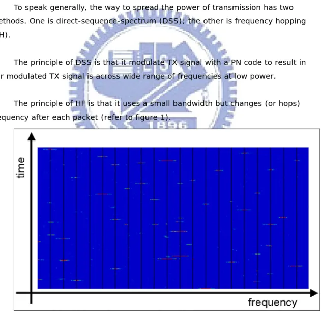
To speak generally, the way to spread the power of transmission has two methods. One is direct-sequence-spectrum (DSS); the other is frequency hopping (FH).
The principle of DSS is that it modulate TX signal with a PN code to result in our modulated TX signal is across wide range of frequencies at low power.
The principle of HF is that it uses a small bandwidth but changes (or hops) frequency after each packet (refer to figure 1).
are 79 channels in 1MHz,after every packet transmits or receives, BT switches to next channel. If two BTs collide, they will hop off and switch to other channels and retransmit the packets.
2.1.2 The Master, Slave and Piconet
When two BT devices query the existence of each other, it presents that one BT device (master) delivers one specific channel
Frequency-Hopping-Synchronization” (FHS) with both own blue-tooth address (BD_ADDR) and clock to opposite (slave). And the slave stores the two values in own internal memory and simultaneously calculate the sequence based on
BD_ADDR and clock of master. When the sequence is calculated, the slave knows the sequence of frequency hopping of master.
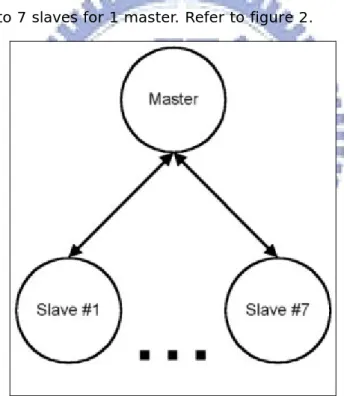
The network is called a simple piconet (one maser, one slave). A piconet at most can expand to 7 slaves for 1 master. Refer to figure 2.
2.1.3 The
Scatternet
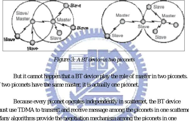
A BT device may exist simultaneously in two piconets. The situation has two possibilities to happen. One is that this device is a master in piconet A but it is a slave in piconet B (Left side in figure 3), too. The other is that the device is a slave in piconet A but it is a slave in piconet B (Right side in figure 3), too. The two piconets are called one scatternet of BT.
Figure 3:
A BT device in two piconetsBut it cannot happen that a BT device play the role of master in two piconets.
If two piconets have the same master, it is actually one piconet.
Because every piconet operates independently in scatternet, the BT device
must use TDMA to transmit and receive message among the piconets in one scatternet.
Many algorithms provide the negotiation mechanism among the piconets in one
2.1.4 The BT Protocol
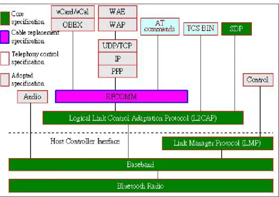
We can describe protocol stack of BT in the following figure. It separates four
parts such like
z
Core specificationz
Cable replacement specificationz
Telephony control specification (TCS)z
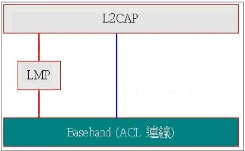
Adopted specification2.1.4.1 Link Manager Protocol (LMP)
The LMP takes care several topics such as z Sending/Receiving Data
z Setting up connection
z Error detection/correction. BT will enclose a CRC after the end of every packet and it will let the receiver check easily if the packet is error free. BT also uses error correction such like either 1/3 rate FEC or 2/3 rate FEC to correct the packet if possible. If the packet is lost, BT uses the “automatic retransmission request”(ARQ) to retransmit the lost packet until the acknowledgement is returned back.
z Power management. BT has three low power modes such like Sniff, Hold and Park mode. Sniff mode is that BT listens to a piconet at a reduced rate. Park mode is that BT device listen at a normal rate and synchronize with a piconet but it does not participate sending/receiving in the piconet. Hold mode is similar to the Park mode except that Active Member Address (AM_ADDR) is retained.
z Authentication
z Deriving the hop sequence. Because the master will deliver this BD_ADDR and its clock to slave, the slave must base on these two values to generate the sequence of hopping to tell RF when and how to hop the frequency.
2.1.4.2 Logical Link Control Adaptation Protocol (L2CAP)
The L2CAP of BT is similar to LLC of GPRS in cellular phone. We will describe this section more detail.
L2CAP is actually a multiplexer to contain many applications enclosed with different logical channel (refer to figure 5). Every logical channel has a starting logical channel identifier (CID) plus payload data. We can separate L2CAP by both signaling and transmission two parts to speak.
Figure 5:
CID of BT2.1.4.2.1 Signaling
L2CAP requests to create the signaling channel whether it is voice or data to master/slave. L2CAP uses LMP to create this signaling channel (refer to figure 6).
Figure 6:
Signaling and Data channel of L2CAP2.1.4.2.2 Transmission
L2CAP contains many applications enclosed with different logical channel identifier (refer to figure 7). These applications include RFCOMM, voice, SDP and TCS.
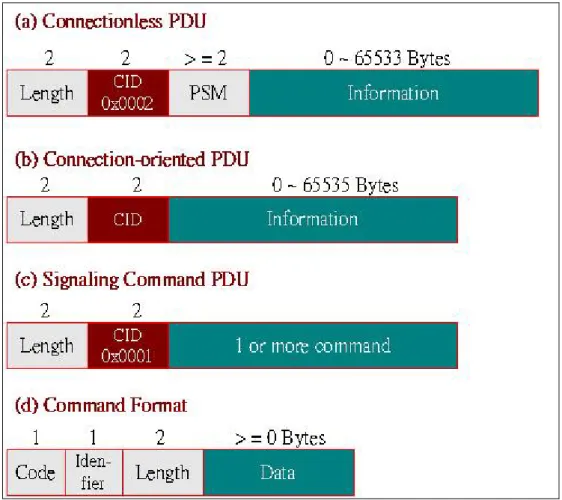
2.1.4.2.3 L2CAP Packet Format
We can separate L2CAP packet into two parts. One is transmission packet, the other is signaling packet. The generic format of packet invokes three major
elements (length, channel identify (CID), Information).
Length occupies two bytes that represent the size of byte of the information
element excluding CID. CID also occupies two bytes that represent the channel identify code. Information occupies from zero to 65535 bytes that can be either data or command depending on which type of packet (transmission or signaling).
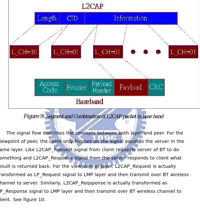
Figure 8:
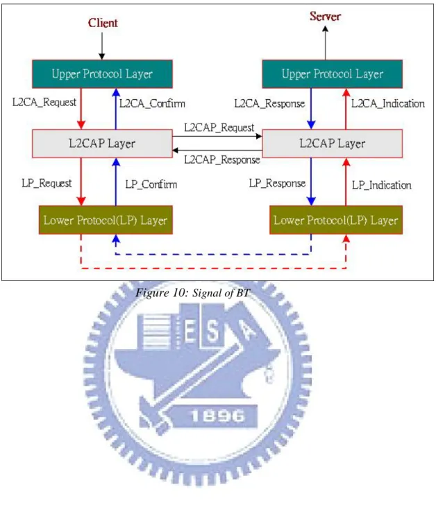
Format of Packet in L2CAPpayload element in base band frame. A baseband frame is composed with access code, header, payload header, payload and crc. Every segment will be combined in another peer by using the element of payload header to tell the peer it is a segment frame and which sequence number in the L2CAP packet.
Figure 9:
Segment and Combination of L2CAP packet in base bandThe signal flow describes the concepts between both layer and peer. For the viewpoint of peer, the client only focuses on the signal equal to the server in the same layer. Like L2CAP_Request signal from client requests server of BT to do something and L2CAP_Response signal from the server responds to client what result is returned back. For the viewpoint of layer, L2CAP_Request is actually transformed as LP_Request signal to LMP layer and then transmit over BT wireless channel to server. Similarly, L2CAP_Reqsponse is actually transformed as
LP_Response signal to LMP layer and then transmit over BT wireless channel to client. See figure 10.
2.1.4.3 RFCOMM
RFCOMM is a protocol located over L2CAP. Its specification is a subset of ETSI TS 07.10 specification. TS 07.10, it is a specification describing the multiplexer of logical channels creating by HDLC. The number of logical channel is at most 60 and practical number of use depends on implementation specific.
In the type of device, two types are mandatory. One is device type 1, the other is device type X. The device type 1 is communication endpoints such like computer and printer. The device type X is part of communication segment such like modem.
RFCOMM frame includes the elements emulating the signal of RS232 9 pins. The elements are shown as follows:
Pin Circuit Name 102 Signal Common 103 Transmit Data (TD) 104 Received Data (RD) 105 Request to Send (RTS) 106 Clear to Send (CTS) 107 Data Set Ready (DSR) 108 Data Terminal Ready (DTR)
109 Data Carrier Detect (CD)
125 Ring Indicator (RI)
Table 1:
Signal of RS232 9 PinRFCOMM emulates the case of null modem, too. It is a special case in TS 07.10. The way in which TS 07.10 transfers the RS-232 control signals creates an implicit null modem when two devices of the same kind are connected together.
The Data Link Connection Identifier (DLCI) is an element of 6 bits that is ongoing in connection between a client and a server. If a BT device supports multiple
session uses a CID to identify.
2.1.4.4 Service Discovery Protocol (SDP)
The SDP can help BT to discovery which type of services in another BT device.
These types include HS/HF, FTP, SPP, OPP, DUN etc. SDP can be done after either
inquiring or pairing for another BT device.
2.2
Bluetooth Stack of Broadcom
The Bluetooth stack of Broadcom is modular, robust and maintainable across any embedded phone platform or OS. It includes either an RTOS abstraction layer or a Generic Kernel Interface (GKI), and a variety of interfaces for any common platform and OS. GKI can be configured to run as a simple OS or used as a software abstraction layer that resides between the Bluetooth protocol stack and platform OS. GKI reduces time-to-market by enabling easy porting to any OS without requiring modification to the stack.
The ANSI C source code is fully compliant with the BT Core Protocol Specification V1.2, including: z L2CAP z RFCOMM z TCS z SDP z OBEX z BNEP z AVDTP z AVCTP
The ANSI C source code is fully compliant with the BT Specification V1.2 and is integrated in Xpress application blocks, including:
z Device Manager (DM)
-Discover BT devices
-Discover BT services
-Configure local device settings
z Data Gateway (DG)
-Dial-up Networking (DUN) server -FAX server z AG -HSP AG -Hands-free Profile (HFP) AG z File Transfer (FT) -FT Profile (FTP) Server
-FTP Client put and pull-OPP client file put
z Advanced Audio (AA)
-AA Distribution Profile (A2DP)
-Audio/Video Remote Control Profile (AVRCP)
z Other Profiles
2.3
Mobile System Software Architecture of MTK
Figure 12:
Architecture of Software of MTK2.3.1 OS and Inter-ware Layer
Basically, MTK currently uses the nucleus OS as the kernel of software. However, for the performance and efficient in the future, MTK makes an inter-ware layer called “Kernel Adaptation Layer” (KAL) that separates application from operation system easily. With it, MTK can easily replace the nucleus OS with another OS.
2.3.2 Protocol
Layer
MTK adopts the similar architecture with OSI layer 7 and follows up ETSI GSM/GPRS specification to make as the protocol layer. We can roughly divide it as L1, L2, L3 and L4 layer.
2.3.2.1 Layer 1
L1 includes Radio Resource (GSM) and MAC. It majors on the
allocation/de-allocation of logical channels such like (P) TCH, listening of Paging Channel and synchronization of Synchronization Channel (SCH) and measurement and report of signal strength to base station.
2.3.2.2 Layer 2
L2 includes Mobility Management (GSM). It majors on the
registration/de-registration of network and location update of cellular phone to base station.
2.3.2.3 Layer 3
L3 covers Call Control (CC), Short Message Service/Cell Broadcast (SMS/CB), Supplementary Service (SS) and RLC. The CC handles the setup and release of Mobile Originated (MO) call, and the answer and disconnection of Mobile Terminated (MT) call. The SMS majors on the transceiver of SMS. The SS handles the
registration, erasure, activation, de-activation and query about the specific service like call waiting, call forwarding and multi-party call.
2.3.2.4 Layer 4
L4 covers conflict management of resources. For example, when you want to dial FDN, you must check if FDN list is enabled and the dialing number is found in the FDN list. MTK encloses the related management of the conflict resources as the
2.3.3 GUI
Layer
The GUI layer is called Man-Machine-Interface (MMI). It can show the scenario of user operation interface.
3 Approaches of Integrating BT with MTK Platform
We use bottom-up way to design the architecture.Firstly, we found that the stack of Broadcom can be ported to any platform; you must let GKI use system service of OS. But once, we let GKI use the system service of OS.; it can result in the neck of system service of OS. because KAL uses them, too. Thus, the best way is that GKI is isolated from OS. and GKI uses APIs of KAL to let KAL be the only interface layer to face to OS. So far, we can fix the problem of resource of system for OS APIs.
Secondly, because MTK memory management is managed by specific
mechanism of memory management not directly managed by OS; while, the stack of Broadcom uses memalloc () API to create the dynamic memory from heap. Hence, it will be out of control in MTK architecture. For this, we program a static memory block to let Broadcom use and manage them. The purpose of this block memory is to let Broadcom to create the internal queues and work as their original dynamic memory usage.
Thirdly, we think of how to print out the debug message when integrating stack of software of Broadcom into MTK. MTK has a debug tool called as “catcher”. In MTK software, it has an associated task to handle the debug message and replace as some special format of message to send them out to the PC tool “Catcher” to display out. Hence, we let software stack of Broadcom include the declaration file of debug API in compilation to use the debug API to display what Broadcom wants to display.
Fourthly, the final work is that we think of how to create these four tasks and their priorities. We adopt the try-and-error way to tune the priorities of these tasks to reach the most robust and smoothest effect when running the system.
The scope of this research covers MMI, PS, driver and system (OS). The
diagram fully describes the whole architecture of software integrating BT with MT
Figure 13:
A new architecture integrating BT with MTK3.1 System
Service
To meet this synchronization of the system service of OS between MTK and Broadcom BT, we build the hierarchical architecture of “Generic Kernel Interface” (GKI) over “Kernel Adaptation Layer” (KAL). GKI is similar to KAL. For the purpose of synchronization and preventing from deadlock in OS, we let GKI call KAL APIs to obtain the service of operation system (i.e., nucleus). These system services are shown as follows: send event, wait for event, delay and get task id.
Besides, a critical point is that BT task needs update of software timer tick to work as internal timer tick of BT tasks to do anything that they would like to do. For example: re-flesh time of interval between previous event and next event.
3.2 Tasks
creation
Figure 14:
Relation between AG and HFBroadcom stack uses four tasks to be created after kernel is loaded. They are BTA, BTU, HCI and BTE_Idle tasks.
BTE_Idle task will play the unit-test role during BT initial period. For example, the
and transmit the message from BTU to L4. Actually, BTA is separated as both BTUI and BTA body two modules. BTUI will get the message from BTA message queue and decode as Broadcom internal message format to send to BTA body. BTA body handles the payload data to related profile body to communicate with BTU task.
BTU task is the protocol stacks body of Bluetooth. It invokes the RFCOMM, SDP, LMP
and L2CAP.
In handling AT commands from remote site, BTU task has two ways to handle this case. One is “PARSING MODE”; the other is “PASS-THROUGH MODE”.
The “PASRING MODE” is actually that BTU will parse AT command request from remote site and then transform as associated message or primitive sent to higher layer task. BTU receives the associated message or primitive of response of AT command from high layer task and transforms as HCI frame carrying with response of AT command to remote site.
The “PASS-THROUGH MODE” is actually that BTU will both deliver AT command request from remote site to higher layer task and receive the response of AT command from high layer task to remote site. Please refer to BT HS/HF specification.
HCI task is the driver interface layer. It will pack the BTU data gram into HCI payload.
HCI will call the UART2 APIs provide by our driver to send out to Broadcom BT module. HCI also decodes the HCI payload data from BT hardware module by UART2 as BTU data gram to send up to BTU task.
Besides, HCI will face this situation when payload data is overflowed in both directions. Here, we adopt the hardware software flow to control the throughput between MTK chipset and Broadcom BT module. In addition, when the BT module is waken up by the event from remote site, we must make sure the flow control is off before MTK chipset is waken up from sleep mode to prevent from data loss.
3.3
Message creation for function
The message creation process is shown as follows:
Firstly, according to scenario requirement in BT of MMI, we must create new messages among MMI, L4 and BTA. These new messages invoke the querying BT device, paring the BT device, discovering the attributes of paired BT device and so on. Here, we separate as major items as follows.
3.3.1 General
Function
The functions invoke as follows:
Action Item Description
BT ready indication When BT is ready, it will send the message carrying with the pointer to BT_INFO to upper layer. This content of BT_INFO invokes the BD address, service mask, power status, paired remote device with BD_ADDR, link-key etc. MMI will set the next command to power on or off the BT module based on the previous power status. MMI also stores the paired device information to show to user.
BT power on/off To power on or off the BT module.
Searching the neighbor BT devices
Before pairing with remote BT device such like handset or headset, we must search the neighbor BT devices.
Canceling searching neighbor BT device
During the period of inquiring the BT device, you can cancel it anytime.
Pairing with dedicated BT device
After searching the BT devices and it is existent, you can go ahead to pair with them.
BT device search own BT device.
To modify name of paired BT device
To modify short name of paired BT.
To kill paired BT device To delete the paired BT from memory.
To modify own BT device BD address
Each BT device has own identify code. It is BD address comprised of 48 bits. It is commonly burn into handset during factory manufacturing process through AT command.
3.3.2 Relevant Profile Function
3.3.2.1 HS/HF Profile
Headset (HS) profile is the earlier profile. Some BT headsets support HS profile. It supports to answer and hung up MT call, audio transfer between handset and headset. (Please refer to BT specification about HS.)
Hand-Free (HF) profile is the later profile than that of HS. It covers HS functionality and supports memory index dialing, phone-number dialing, DTMF, multi-party call, call hold, call active SS service etc. (Please refer to BT specification about HF.)
Action Item Description
To create Audio Connection Link (ACL)
ACL plays a very critical role. All communications of messages between handset (AG) and headset (HF) run over the ACL.
To release Audio Connection Link (ACL)
When radio signal is weak or user would like to close BT device connection, it results in ACL release.
To create SCO Link SCO plays another critical role. The communication of audio between handset (AG)
To release SCO Link When radio signal is weak or user would like to hang up call, SCO link will be released.
About Answer MT call/Make MO call/MPTY call
We adopt the pass-through mode of Broadcom. It
represents that Broadcom will pass through AT command from remote BT device being carried with message MSG_ID_BTUI_L4C_PASSTHROUGH_AT_SOLICITED_CO MMAND_REQ to L4C. Keeping on next step, we follow the AT command parsing and dispatch rule of MTK to work.
To get file from remote Getting a file from remote BT device. You can store the file to phone memory or mini-SD card.
3.3.2.2 FTP Profile
FTP profile is separated as two parts. One is the client of FTP; the other is the server of FTP.
FTP server is more common in current BT handsets. When a remote BT device (such like handset or PC) connects with local BT handset, the remote point can get or send file to local BT handset. At this situation, the local BT handset plays FTP server role.
BT handset can also connect with other BT device such like PC or handset. We can browse opposite FAT, create the folder, delete the folder, send file to or get file from opposite BT device. At this situation, the BT device plays the FTP client role.
Action Item Description
To create connection link of FTP FTP connection link plays a very critical role. The communications of FTP messages between AG and PC or AG run over the FTP connection link.
To browse FAT of remote BT device Browsing FAT structure of remote site. This FAT structure is a special FAT structure not standard FAT8/16/32.
To create a folder Creating a new folder in remote BT device.
To delete a folder Deleting folder in remote BT device.
To send file to remote Sending a file to remote BT device. You can select the file sent from phone memory or mini-SD card.
To get file from remote Getting a file from remote BT device. You can store the file to phone memory or mini-SD card.
3.3.2.3 SPP Profile
The use of Serial Port Profile varies very much. You can use it to work as a wireless COM port.
Any original AP through cable is replaced with BT SPP. Thus, you can access the entries of phone book, send or receive SMS and other function through BT SPP.
3.4
Sleep Mode and Hardware Flow Control
In an embedded system, the control of sleep mode plays a very important role, especially at handset. How to last stand-by time of handset for over 4 days is very challenge for handset system.
In general, the algorithm to reduce power consumption is shown as follows:
Listen to base station paging rate to decide how long the handset can sleep.
The soft interrupt sets the next paging time as sleep period. Moreover, the system’s low priority task will check if the time between two neighbor events is enough to let the system can enter sleep mode. It usually needs 40 ms. If it is OK, the task will swap the clock of system from 13MHZ to 32KHZ to reduce power consumption.
When next soft interrupt is waken up, it will trigger frame interrupt to receive the synchronization from paging frame.
In MTK architecture, we don’t use the above algorithm. Because that MTK does not release the above related source codes of power management. However, MTK guarantees that if we turn off the major devices that consume large current such like LCD, keypad light, back light etc during 30 seconds from power off to power on, the system’s low priority task will reduce the working current from 50~80 mA (idle mode) to 2mA (sleep mode).
The Bluetooth of Broadcom consumes the working current about 15mA but its sleep current is very small about 10 nA. The problem is how to make sure the sleep mode working well between the system and BT. It has some criterions as follows:
When BT is at sleep mode, remote site wakes BT up. BT will inform handset and wait for handset to inform it to send data to handset by hardware flow control (RTS/CTS).
Based on the above criterions, we can keep on programming the driver for meeting the requirements of sleep mode. However, the other applications share too many GPIOs with interrupt to no other GPIO with interrupt to be shared with BT. Hence, we encounter some trouble here. It means that we cannot use the interrupt easily to meet the target for sleep mode.
The only way to meet the target of sleep mode is that we must use GPIO without interrupt and use polling way to read the wake-up event. This is the most difficult part. Because Broadcom AE uses interrupt not polling way to reach the target for LG or Samsung.
The algorithm of polling is shown as follows:
We create a periodical timer with specific interval. The interval is not random to decide. It needs to query BT task to get the tick gap for next event. We take it as the interval of timer. It must either be large enough to let the system enter sleep mode (e.g. 50 ms above) when nothing is to be handled or be small enough to let the system work normally when something is handled (e.g. 10ms).
When the timer is expired, it must kick timer update of BT. The HCI task of BT can check the value of GPIO to see if the BT module requests to send data to system. If it is true, HCI must set as logic “High” of RTS to BT module to begin to transmit data.
When the BT task has nothing to do, it must set interval as 50 ms above. And HCI task of BT will set as logic “Low” of RTS to prevent from BT module sending data to system to result in the situation of data loss.
4 Implementation of the New System Architecture
4.1 L4
Subsystem
Here, we will focus on BTM because it is the major core of BT in L4.
4.1.1 BlueTooth Manager Module
Based on the architecture of MTK, we implement an abstract module called Blue Tooth Manager (i.e. BTM) module. BTM is an abstract module and is located under L4 actually.
4.1.2 BTM
Function
L4A will receive the message of BT from MMI and call the associated APIs of BTM. And then BTM will call another APIs that packs into message sent to BTA task.
BTM will also receive the message from BTA and call the APIs to pack message sent to MMI.
BTM will receive the message carrying AT command from BTA.BTM will call API to en-queue at command to ring buffer.
Figure 16:
Interface among MMI, BTM and BTA4.2 BT
Subsystem
4.2.1 BTA
Module
Its interface with upper layer is L4 layer. Its interface with lower layer is BTU module.
Besides, BTA module is separated into two parts, BTUI and BTA body.
4.2.1.1 BTUI
The internal-process mechanism in software of Broadcom is different from that of MTK. These modules in Broadcom use their internal queue different from that of MTK. At compile time, Broadcom’s code allocates a large static memory space to work as the usage of their internal memory. The memory area will be separated as individual module’s queue, global variable area, and control buffer area etc. When each module wants to send message to other module, it needs to pack into message and call GKI API to send to opposite’s queue.
A generic format of data structure of message is shown as follows. Taking BTA message as an example.
Figure 18:
Message Format between BTM and BTAtypedef struct {
BT_HDR hdr; xxx xxx;
{ UINT16 event; UINT16 len; UINT16 offset; UINT16 layer_specific; } BT_HDR;
Each message has a specific tag defined at the “event” field of BT_HDR.
At each module, if module “A” wants to send message to module “B”, then it will allocate a message size from GKI API and pack the related value to fields. For example, it will set the “event” field of BT_HDR as an identity code of a specific message. And it also sets the relevant value or array at “xxx” field. After the above thing is finished, module “A” will call GKI API to en-queue the message to module “B”. Next, module “A” will call GKI API GKI_send_event () to inform module “B” that a message is sent to its queue. This is the internal inter-process mechanism of Broadcom BT.
Next, we will discuss how BTA communicates with BTM. Basically, BTA has just BTA body originally. BTA body can receive upper layer command from MMI and transform as internal message sent to next layer.
Because the BTM only sends message to BTA, BTA will be separated as both BTUI (message interface) and BTA body (API interface). For this reason, BTA task is the only task that has two types of queues among the tasks in Broadcom. One is internal module queue of Broadcom, the others is the task message queue of MTK. Its function is shown as follows.
Figure 20:
Integration of IPC between MTK and BroadcomBTM will send the message of MTK format to BTA’s external queue (it is created by MTK code during the period of kernel initialization).
BTM will call GKI_Kal_send_event (MOD_BTA, L4_TO_BTUI_EVENT) to inform BTA module.
we use the following two steps to finish the job.
First, BTM must finish the above two items. Second, after OS. context switches and BTA task is at the run state of OS., BTA will call GKI_Kal_wait () to detect if BTM sends message to BTA. If yes, BTA will call the API
BTUI_Get_Message_From_Queue () to get the message from the external queue of
BTA.
At the API, BTUI_Get_Message_From_Queue, the implement of the algorithm is shown as follows:
Running stack_set_active_module_is () to set TST flag. The action will activate the message sent to primitive debug tool.
Running receive_msg_ext_g () to get message from BTA external queue. If the queue is empty, the BTA will get garbage information.
Then, it transforms the message content as that of Broadcom when one message is received from BTM. At the end, it will tell BTA if the queue has still pending message(s) inside. If the value returned to BTA task is not zero, BTA will continue to read till the value is zero. It will prevent from situation of starvation of OS. to happen.
After BTA task receives the transformed message content from module “BTM”, it will send the message to next layer by Broadcom’s inter-process mechanism. Note the next layer may be itself or lower layer module.
4.2.2 BTU
Module
Figure 21:
Architecture among BTA, BTU and HCIThe module BTU is the kernel of protocol stack of BT. It follows the specification of BT to run the actions. Please refer to the specification of BT.
Here, we will talk two types of APIs related with MTK system. One is the file system APIs and the other is NVRAM APIs.
4.2.2.1 File System
When BT runs the FTP service whether it is client or server or not, it needs to store the file to or get the file from file system whether it is either mini-SD card or
4.2.2.2 NVRAM
It stores the relevant setting about the BT device such like BD address and name of local BT device, the information of paired remote BT device such like BD address, link key, short name etc, BT power on and off status.
4.2.3 HCI
Module
Figure 22:
Interface between HCI and Physical BT modemThe module “HCI” is the kernel of device driver of BT. Because it must use UART2 of MTK chipset to work as the transceiver of BT physical frame; it will call the UART2 APIs of MTK to attain the target.
KAL provides an associated service API of operation system to upper layer. It has two benefits for such architecture.
First, we can replace operating system easily. Second, we can do something such like debug sniffer, memory budget control, even something else with PC’s tool.
Broadcom’s code base has the similar intermediate layer with KAL, “Generic Kernel Interface”. Afterwards, we will call it “GKI”. Any message communication inside Broadcom subsystems will be finished by way of GKI.
We follow the MTK architecture up to implement GKI.
Figure 23:
The new architecture between GKI and KALGKI is the software kernel in Broadcom. It supplies related APIs to Broadcom internal modules to call. Some APIs in GKI need the help from operation system. Hence, we put GKI above KAL to let GKI uses KAL relevant API easily. Through the help from KAL, GKI indirectly obtains the service from operation system.
5 Experiment and Result
According to implementation on HS/HF, FTP and SPP profiles, we make the experiment on FTP client and server two parts for upload and download speed. About the HS/HF and SPP, we cannot test any meaningful test cases. Hence, we just test the FTP related test cases.
We compare these test cases among SONY-ERICSSON S700i, MOTO V3 and I-Mobile TV901. TV901 is the product using software architecture of this thesis plus Broadcom BT with MTK platform.
5.1
FTP Client Test Items
For FTP client test items, we separate as two test cases. One is “FTP client forward”; the other is “FTP client get”.
5.1.1 FTP Client (Forward)
The “FTP client – Forward “ test procedure is shown as follows: To use Broadcom BT’s dongle in PC,
z The handset connects with PC by way of BT dongle.
z From handset memory, we send the file with specific size to PC. z We test 3 times for specific size of file and then average them. z This time unit is second.
I-Mobile
TV901
I-Mobile
TV901
I-Mobile
TV901
Motor
V3
Motor
V3
Motor
V3
Sony
S700
Sony
S700
Sony
S700
100kbytes 1Mbytes 2Mbytes 100kbytes1Mbytes 2Mbytes 100kbytes 1Mbytes 2Mbytes
1st test
5
52
98
10
73
114
10
56
95
2nd test
5
50
95
10
78
101
9
55
97
3rd test
5
53
97
11
78
118
9
56
95
Average 5
51.6667
96.667
10.3333
76.333
111
9.33333
55.667 95.6667
Table 2:
Comparison of Throughput among TV901, V3 and S700 at FTP Client Forward0 20 40 60 80 100 120
100kbytes 1Mbytes 2Mbytest
Motorola V3
SONY-ERICSSON S700 i-Mobile TV901
5.1.2 FTP Client (Get)
The “FTP client – Get “ test procedure is shown as follows: To use Broadcom BT’s dongle in PC,
z The handset connects with PC by way of BT dongle. z We get the file with specific size from PC.
z We test 3 times for specific size of file and then average them. z This time unit is second.
*Motorola V3 does not support this function.
I-Mobile
TV901
I-Mobile
TV901
I-Mobile
TV901
Motor
V3
Motor
V3
Motor
V3
Sony
S700
Sony
S700
Sony
S700
100kbytes 1Mbytes 2Mbytes 100kbytes1Mbytes2Mbytes100kbytes 1Mbytes2Mbytes
1st test
7
60
119N/A
N/A
N/A 8
59
119
2nd test
7
61
120N/A
N/A
N/A 8
60
118
3rd test
6
59
118N/A
N/A
N/A 7
60
118
Average 6.6667
60
119 #DIV/0! #DIV/0! #DIV/0!
7.66667 59.667 118.33
Table 3:
Comparison of Throughput among TV901, V3 and S700 at FTP Client GetFTP Client (Get) 0 20 40 60 80 100 120 140
100kbytes 1Mbytes 2Mbytest Throughput
Second
Sony-Ericsson S700 I-Mobile TV901
5.2
FTP Server Test Items
5.2.1 FTP Server (Forward)
The “FTP server – Forward “ test procedure is shown as follows: To use Broadcom BT’s dongle in PC,
z PC looks for handsets with BT.
z PC connects with the specific handset.
z PC sends the file with specific size to the handset memory. z We test 3 times for specific size of file and then average them.
z This time unit is second.
I-Mobile
TV901
I-Mobile
TV901
I-Mobile
TV901
Motor
V3
Motor
V3
Motor
V3
Sony
S700
Sony
S700
Sony
S700
100kbytes 1Mbytes 2Mbytes 100kbytes 1Mbytes 2Mbytes 100kbytes 1Mbytes 2Mbytes
1st test
8
67
133
15
199
557
7
36
70
2nd test
8
67
133
17
209
552
8
36
70
3rd test
8
68
133
17
210
583
7
36
69
Average 8
67.333
133 16.33333
206
564
7.33333
36 69.6667
Comparison of Throughput among TV901, V3 and S700 at FTP Server Forward
FTP Server (Forward) 0 100 200 300 400 500 600
100kbytes 1Mbytes 2Mbytest Throughput
Second
Sony-Ericsson S700 Motorola V3 I-Mobile TV901
5.2.2 FTP Server (Get)
The “FTP server – Get “ test procedure is shown as follows: To use Broadcom BT’s dongle in PC,
z PC looks for handsets with BT.
z PC connects with the specific handset.
z PC gets the file with specific size from the handset memory. z We test 3 times for specific size of file and then average them. z This time unit is second.
I-Mobile
TV901
I-Mobile
TV901
I-Mobile
TV901
Motor
V3
Motor
V3
Motor
V3
Sony
S700
Sony
S700
Sony
S700
100kbytes 1Mbytes 2Mbytes 100kbytes 1Mbytes2Mbytes 100kbytes 1Mbytes2Mbytes
1st test
5
37
70
4
25
49
4
32
64
2nd test
5
34
71
4
25
55
5
32
64
3rd test
4
35
70
3
25
52
4
32
64
Average 4.666667
35.333
70.333
3.66667
25
52
4.33333
32
64
Table 4:
Comparison of Throughput among TV901, V3 and S700 at FTP Serve GetFTP Server(Get) 0 10 20 30 40 50 60 70 80
100kbytes 1Mbytes 2Mbytest Throughput
Second
Sony-Ericsson S700 Motorola V3 I-Mobile TV901
5.3 Results
From the results of the experiments, we observe some conclusions in I-Mobile TV 901 problem.
5.3.1 Discussion on the test
From the discussions of the above two sections, we make the table 4 to summarize the result for both client and server.
Test Item Best Performance Middle Performance Worse Performance
FTP Client TV901 S700 V3 FTP Server (Forward) S700 TV901 V3 FTP Server (Get) S700 V3 TV901
Table 5:
Summarize of Performance in FTP test itemsExcept for “FTP Server (Get)”, TV901 and S700 have nearly performance at the other two test items (FTP Client and FTP Server Forward). At the test item of “FTP Server (Get)”, we do two experiments to find the root cause. One is that data is gotten from static memory allocated at compile time. The other is that data is gotten from nvram by way of transform of file system of Winbond. The performance in the front is two times more than that of the last one. Here, we make sure the root cause is in the file system of Winbond.
5.3.2 Improved
method
From the above analysis, we can understand file system is the root cause in our practical test at FTP server. For improving the performance, we have one way to finish the target. The way is performance tuning between nvram and file system.
We will use the macro block tuning to result in whole performance improving. Firstly, we will focus on loop such like for, while or do loop in C code. Any loop may include some redundant code inside. In a non-loop environment, we may
time. When n is a big value, the time is more. Keeping on modifying such code and measuring the running time to reduce time. Such improvement usually takes a great effect in performance.
Secondly, we focus on function call. We know function call uses the push and pop skill at the stack. For the timing issue, the stack skill may result in the non-necessary waste of time. Hence, unless it is needed (e.g. we confirm that function call plays the key role in convenience and maintain), we will do the best to use the macro enclosing with the content of the function to replace the function call in code. Of course, it may result in inconvenience in programming.
6 Conclusion
In this thesis, we implement a BT solution with MTK handset. To reach this target, we propose the system architecture of software and risk analysis in implementing BT to MTK platform in advance. For the possible risks such like dynamic memory allocation, GKI in Broadcom solution, we make the feasibility analysis before the code is implemented in advance. And it actually helps us to break down some issues we may happen in the middle even last period of implementing BT with MTK platform.
In dynamic memory part, we replace it with static memory in compile time to reach the mechanism of memory management in MTK platform. This part lets us to understand memory allocation and management in integrating two different modules plays the critical role.
In GKI part, we replace the way of GKI over nucleus OS with GKI over KAL. It lets us to overcome resource conflict problem in the future.
From the result, we find that our performance is less than S700. And we find the root cause is in file system framework of Winbond. Based on this issue, we do the suggestion in improving performance.
Reference
[1]Bluetooth specification version 1.0– Hands-Free Profile, McGraw-Hill, New York, 1968.
[2]Bluetooth specification version 1.1 – Headset Profile, McGraw-Hill, New York, 1968.
[3]Bluetooth specification version 1.1 – Serial Port Profile, McGraw-Hill, New York, 1968.
[4]Bluetooth specification version 1.1 – File Transfer Profile, McGraw-Hill, New York, 1968.
[5]3GPP TS 27.007 v7.1.0- AT command set for User Equipment (UE), 2006.6
[6]3GPP TS 24.008 v7.4.0- Mobile radio interface Layer 3 specification; Core network protocols; Stage 3, 2006.6
[7]3GPP TS 23.040 v6.7.0- Technical realization of Short Message Service (SMS), 2006.3
[8]3GPP TS 24.010 v6.0.0- Mobile Radio Interface Layer 3 - Supplementary Services Specification - General Aspects, 2005.1
[9]3GPP TS 27.005 v7.0.0- Use of Data Terminal Equipment - Data Circuit terminating Equipment (DTE-DCE) interface for Short Message Service (SMS) and Cell Broadcast Service (CBS), 2006.3
Bibliography
Author: Yung-Hui, Kuo (David Kuo)
Birthday: 1971/08/14
Education:
z B.S. : Electronic Engineering Department, National Taiwan University of Science and Technology (1995 – 1997)
z M.S. : Electronic Engineering Department, National Taiwan University of Science and Technology (1997- 1999)
z M.S. : CSIE program, part time master, college of Computer Science, Nation Chiao Tung University (2002 – 2007)
Working Experience:
z Software engineer, wireless communication BU, BENQ(1999.7 - 2000.11) z Software engineer, RPM, Applied Materials Taiwan (2000.11 - 2001.5) z Specialist, wireless communication BU, Quanta Computer (2001.6 -
2003.9)
z Assistant Manager, Darts Technology (2003.9 – 2006.4)