適用於行動隨意網路之混和覆蓋式群播路由協定
57
0
0
全文
(2)
(3) 適用於行動隨意網路之混和覆蓋式群播路由協定. A Hybrid Overlay Multicast Routing Protocol for MANETs. 研 究 生:陳琮闓. Student:Chaung-Kai Chen. 指導教授:王國禎. Advisor:Kuochen Wang. 國 立 交 通 大 學 資 訊 科 學 系 碩 士 論 文 A Thesis Submitted to Department of Computer and Information Science College of Electrical Engineering and Computer Science National Chiao Tung University in Partial Fulfillment of the Requirements for the Degree of Master in Computer and Information Science June 2004 Hsinchu, Taiwan, Republic of China. 中華民國九十三年六月.
(4)
(5) 適用於行動隨意網路之混和覆蓋式 群播路由協定. 學生:陳琮闓. 指導教授:王國禎 博士. 國立交通大學資訊科學系. 摘 要 本論文提出一個基於行動隨意網路之群播路由協定,稱為混和覆 蓋式群播路由協定(HOMRP)。行動隨意網路下現有的覆蓋式群播路由 協定有高傳遞延遲之主要缺點。為了改善這個缺點,我們整合群播封 包封裝與單傳隧道機制,以提供有效的資料傳遞。HOMRP針對每個群 播群組建立了多個區域群播樹。在區域群播樹中,所有的父節點與子 節點距離皆位於彼此的訊號範圍內,並利用群播封包封裝方式來傳遞 群播封包。此種方式可以提高資料轉送的效率。另外,區域群播樹間 是利用單傳隧道方式傳遞封包。此外我們為每一個區域群播樹指定一. i.
(6) 個識別碼,以避免區域群播樹間產生迴圈路由。針對行動隨意網路之 高變動性,HOMRP 採用一個整併樹機制以提高封包傳遞之效率。HOMRP 採用兩階段氾濫發送之機制,此機制利用指定TTL之大小,以限制控 制訊息發送之範圍,以降低控制訊息的過渡氾濫。 HOMRP並沒有指定使用任何特定的單傳協定,因此它可以運作於 任何單傳路由協定上。另外,HOMRP之路由維護是由群播之每一個成 員所發動的。所有的群組成員只需要瞭解其鄰近群組成員,而不是所 有的群組成員。在HOMRP中多個群播發送者可以共用同一種路由架 構,因此可以大大地增加路由的維護效率。在模擬中,我們嘗試與 ODMRP與AMRoute做比較,以封包傳遞效率來說,HOMRP與ODMRP同有較 高的傳遞效率,而相較於AMRoute,HOMRP提升了50%的傳遞效率。另 外,HOMRP在控制耗費上比ODMRP減少了18%,於點對點之傳輸延遲上, HOMRP比AMRoute減少了9%。總之,相較於其他群播方式本論文所提出 之群播路由協定可以提供較低的控制耗費並提供較高的傳遞效率,並 適合於多發送者之群播應用。. 關鍵詞:混和覆蓋式群播、隨意網路、行動隨意網路。. ii.
(7) A Hybrid Overlay Multicast Routing Protocol for MANETs Student:Chaung-Kai Chen. Advisor:Dr. Kuochen Wang. Department of Computer and Information Science National Chiao Tung University. Abstract We propose a novel multicast routing protocol, called hybrid overlay multicast routing protocol (HOMRP) for MANETs (Mobile Ad hoc NETworks). Existing overlay multicast routing protocols in MANETs have the main drawback of high packet delivery delay. In order to improve this shortcoming, we integrate multicasting and unicast tunnels for efficient packet delivery. In HOMRP, it creates multiple local multicast trees. Each pair of parent node and child node in a local multicast tree is at a distance of one-hop. It uses multicasting to deliver multicast packets in local multicast trees. This will provide efficient data forwarding. Unicast tunnels are used for transmitting packets between local multicast trees. To avoid looping routes between local multicast trees, each local multicast tree is assigned a tree ID. To deal with dynamic changing of network topology in MANETs, HOMRP uses a tree consolidation scheme for highly efficient data forwarding. In addition, in order to reduce the overhead of control messages flooding, we adopt two-level flooding for member discovery by limiting the value of TTL in a packet. HOMRP does not restrict to use any specific unicast routing protocol; hence it can operate with any unicast routing protocols. Route maintenance in HOMRP is initiated by each multicast group member. Each member only needs to maintain the nearby members. The same route structure of a multicast group can be shared by multiple senders (sources); this brings iii.
(8) high efficiency of route maintenance. Simulation results have shown that the packet delivery ratio of HOMRP is close to that of ODMRP and is 50% better than that of AMRoute. HOMRP reduces 18% control overhead compared to ODMRP and reduces 9% end-to-end packet delay compared to AMRoute. In sum, HOMRP provides lower control overhead, high packet delivery ratio and is especially suitable for multicast applications with larger number of senders, compared to other approaches.. Keywords:hybrid overlay multicast routing, ad hoc networking, MANETs.. iv.
(9) Acknowledgements Many people have helped me with this thesis. I am in debt of gratitude to my thesis advisor, Dr. Kuochen Wang, for his intensive advice and instruction. I would like to thank all the classmates in Mobile Computing and Broadband Networking Laboratory for their invaluable assistance and suggestions. The support by the National Science Council under Grant NSC92-2213-E-009-078 is also grateful acknowledged. Finally, my families deserve special mention. This thesis is dedicated to them for their support.. v.
(10) Contents. Abstract ( in Chinese ) ................................................................................................. i Abstract ( in English )................................................................................................ iii Acknowledgements...................................................................................................... v Contents ...................................................................................................................... vi List of Figures............................................................................................................. ix List of Tables............................................................................................................... xi List of Algorithms...................................................................................................... xii Chapter 1 Introduction............................................................................................... 1 Chapter 2 Related Work............................................................................................. 4 2.1 Categories of Multicast Routing for MANETs ............................................... 4 2.1.1 Tree-based approach ............................................................................ 4 2.1.2 Meshed-based approach....................................................................... 5 2.1.3 Overlay Approach................................................................................ 6 2.2 Control Messages Flooding for Multicast Routing Protocols in MANETs .... 7 vi.
(11) Chapter 3 HYBRID OVERLAY MULTICAST ROUTING PROTOCOL (HOMRP)..................................................................................................................... 9 3.1 Overview of the Proposed Protocol ................................................................ 9 3.2 Categories of Multicast Group Members...................................................... 10 3.3 Multicast Connection Table .......................................................................... 12 3.4 Member Discovery and Route Selection....................................................... 13 3.5 Efficient Routes............................................................................................. 19 3.6 Local Multicast Tree Consolidation .............................................................. 20 3.7 Member Disjoin and Fast Recovery.............................................................. 22 3.8 Packet Delivery ............................................................................................. 24 3.9 Route Maintenance ....................................................................................... 24 3.10 Data Structures for Implementation ............................................................ 25 Chapter 4 SIMULATION AND DISCUSSION...................................................... 27 4.1 Simulation Environment ............................................................................... 27 4.2 Evaluation of Different Group Sizes............................................................. 28 4.3 Comparison with Other Approaches ............................................................. 31 Chapter 5 CONCLUSIONS AND FUTURE WORK ............................................ 35 5.1 Concluding Remarks..................................................................................... 35 5.2 Future Work .................................................................................................. 36. vii.
(12) Bibliography .............................................................................................................. 37. viii.
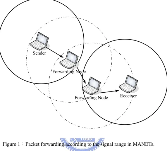
(13) List of Figures Figure 1:Packet forwarding according to the signal range in MANETs. .................. 2 Figure 2:The architecture of HOMRP and its packet delivery. ............................... 12 Figure 3:Member discovery within the signal range............................................... 16 Figure 4:Member discovery out of the signal range. .............................................. 17 Figure 5:Flowchart of member discovery based on Algorithm 1............................ 19 Figure 6:The tree consolidation procedure.............................................................. 21 Figure 7:Flowchart for member disjoin based on Algorithm 3............................... 23 Figure 8:Packet delivery ratio as a function of mobility speed............................... 29 Figure 9:Control overhead as a function of mobility speed. ................................... 30 Figure 10:End-to-end delay as a function of mobility speed. ................................. 30 Figure 11:Packet delivery ratio as a function of mobility speed among different approaches.......................................................................................................... 33 Figure 12:Control overhead as a function of mobility speed among differnent. ix.
(14) approaches.......................................................................................................... 33 Figure 13:End-to-end delay as a function of mobility speed among different approaches.......................................................................................................... 34. x.
(15) List of Tables Table 1:Comparison of multicast routing protocols for MANETs............................. 7 Table 2:Multicast connection table entry. ................................................................ 13 Table 3:JOIN_REQUEST packet format.................................................................. 13 Table 4:JOIN_REPLY packet format. ...................................................................... 14 Table 5:JOIN_COMFIRM packet format................................................................. 15 Table 6:TREE_CONSOLIDATION packet format. .................................................. 20 Table 7:DISJOIN_REQ packet format. .................................................................... 22 Table 8:Simulation Parameters................................................................................. 28. xi.
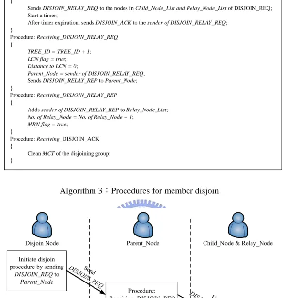
(16) List of Algorithms Algorithm 1:Procedures for member discovery. ...................................................... 18 Algorithm 2:Procedure when receiving TREE_CONSOLIDATION message. ........ 22 Algorithm 3:Procedures for member disjoin............................................................ 23. xii.
(17) Chapter 1 Introduction In recent years, the researches of wireless networks and mobile computing provide more probabilities for wireless mobile networks in the future. Wireless mobile networks are more and more popular and important for our life. In general, wireless mobile networks can be classified into two categories: ad hoc networks and infrastructure networks. Infrastructure networks, such as cellular networks and IEEE 802.11 infrastructure mode, need to construct basic structures, like interconnections of base stations or access points. Communications between base stations or access points are via wire-based structure in infrastructure networks. Ad hoc networks, also called Mobile Ad hoc NETworks (MANETs), are dynamic, distributed and self-organizing networks. There is no need of any infrastructure. So it is suited to construct temporary networks for special situations, such as emergency search, battlefield, temporary conference, classroom, and etc. A sender in MANETs can only transmit within its signal range. If any receiver node which is outside the signal range of the sender, the delivered packets are forwarded by nodes which are between the sender and the receiver node, as shown Figure 1. Mobile nodes have characteristics of mobility, and moving frequently and irregularly in MANETs. In order to maintain connections in unstable MANETs, mobile nodes require keeping exchanging control messages to sustain the links between mobile nodes. 1.
(18) Figure 1:Packet forwarding according to the signal range in MANETs. The protocols of network layer and transport layer in MANETs are based on TCP/IP, like wire-based networks. There are three basic types of transmission: unicast, broadcast and multicast. The basic transmissions can be completed by unicast and broadcast in wire-based networks. However, MANETs are restricted by low bandwidth and limited energy, so it is too expensive to use unicast to complete all kinds of transmissions even if unicast is reliable for transmissions. For instance, when a sender adopts unicast to deliver the same packets to a set of specific receivers in MANETs, it needs to transfer the same packets to different receivers in turn. If this sender adopts broadcast, it consumes large bandwidth. Due to these limitations and characteristics of transmission, multicast can be used for efficient. 2.
(19) bandwidth utilization and energy conservation in MANETs, especially for voice, video, and multimedia streaming. There are several multicast routing protocols which have been proposed and developed for MANETs in recent years. Multicast routing protocols in MANETs can be classified to three major categories, based on how routes are created for the members of the group: tree-based [1], meshed-based [1] and overlay approaches [2]. The tree-based approach has the benefit of high data forwarding efficiency. But, it will lead to link broken easily in high mobility environments. The meshed-based approach has high robustness in comparison with the tree-based approach in high mobility environments. However, in order to maintain the mesh topology it requires more control messages than the tree-based approach. It will increase network load and control overhead. The overlay approach has been proposed to achieve better performance by combining the advantages of both tree and meshed-based approaches. The overlay approach monitors group dynamics, while the underlying unicast protocol tracks network dynamics, resulting in more stable protocol operation and low control overhead even in a highly dynamic environment [2]. In this thesis we proposed a Hybrid Overlay Multicast Routing Protocol (HOMRP) which has the characteristic of overlay and tree-based approaches. The remainder of this thesis is organized as follows. We describe related work of multicast routing for MANETs and efficient flooding in the next chapter. In Chapter 3, we illustrate how HOMRP works in MANETs. In Chapter 4, we evaluate the performance of HOMRP in mobility environments. Finally, concluding remarks and future work are given in Chapter 5.. 3.
(20) Chapter 2 Related Work In section 2.1, we review existing multicast routing protocols for MANETs and compare each protocol by different characteristics. Then, we discuss control messages flooding schemes for different multicast routing protocols in section 2.2.. 2.1 Categories of Multicast Routing for MANETs In this section, we review multicast routing protocols for MANETs, which can be classified into three categories: tree-based, meshed-based and overlay approaches.. 2.1.1 Tree-based approach The tree-based approach is suited to wire-based networks. It has benefits of efficient data forwarding and easy construction. There are a few tree-based schemes proposed for MANETs. Multicast operation of the Ad hoc On-demand Distance Vector routing protocol (MAODV) [3] is a multicast extension of ad hoc on-demand distance vector routing protocol (AODV). It extends operations of route 4.
(21) maintenance in AODV for multicast route maintenance. In MAODV, each multicast route is always the shortest path. Ad hoc Multicast Routing Protocol utilizing Increasing ID numberS (AMRIS) [4] is a shared tree-based on-demand protocol to support multiple senders and receivers in a multicast session. AMRIS assigns a dynamic ID number to each node in a multicast session. AMRIS directs the flow of multicast packets by ranking the ID numbers [4].. 2.1.2 Meshed-based approach Because the tree-based approach only creates a single path between any two multicast group members, it may cause link broken easily in high mobility environments. In contrast to the tree-based approach, meshed-based approach creates multiple paths. Therefore, the meshed-based approach is robust and reliable, especially in high mobility environments. On-Demand Multicast Routing Protocol (ODMRP) [5] is an on-demand meshed-based protocol which uses the concept of forwarding group [6] to maintain multicast routes. In ODMRP, only the members of the forwarding group can forward multicast data. ODMRP is a soft state approach, there is no explicit control message required for a node to leave the group. Dynamic core based multicast routing protocol (DCMP) [7] is an enhancement of ODMRP. It adopts a dynamic core to reduce control messages and improve data forwarding. On-demand multicast routing protocol with multipoint relays (ODMRP-MPRs) [8] is another enhancement of ODMRP. It modified the multipoint relays scheme which was proposed in optimize link state routing (OLSR) [9] to efficient flooding and improves the unidirectional link problem in ODMRP. Similar to ODMRP, the core-assisted mesh protocol (CAMP) [10] is a meshed-based protocol.. 5.
(22) 2.1.3 Overlay Approach In order to achieve better performance, some protocols which combine the advantages of both tree and meshed-based approaches called the overlay approach. Ad hoc multicast routing protocol (AMRoute) [11] is an overlay multicast routing protocol. AMRoute creates a bi-directional, shared tree which is consists of senders and receivers in a multicast group. This shared tree does not consider the actual paths of delivery. All multicast packets are delivered by unicast tunneling in AMRoute. Progressively adapted sub-tree in dynamic mesh (PAST-DM) [12] is an enhancement of AMRoute. It proposes a dynamic virtual mesh that adapts itself to the mobility of network nodes. A novel tree construction algorithm is proposed to make the delivery adapted to the current network topology. Finally, according to the characteristics of topology, loop-free, dependence on unicast protocols, necessity of flooding control messages and necessarily for periodic messages, the above multicast routing protocols for MANETs are compared as shown in Table 1.. 6.
(23) Table 1:Comparison of multicast routing protocols for MANETs [1].. 2.2 Control Messages Flooding for Multicast Routing Protocols in MANETs Most of multicast routing protocols for MANETs need to flood control messages for maintaining multicast group relationship. Efficient flooding improves efficiency of membership maintenance and reduces control overhead. Hence, there are several methods of flooding controlling which have been proposed for multicast routing protocols. The Forwarding Group Multicast Protocol (FGMP) [6] specifies the TTL (time-to-live) field in the packet to limit the range of flooding. It is a simple. 7.
(24) way to efficient flooding. PAST-DM [12] used the concept of route update in the fisheye state routing [13]. It used different update periods for different hopping number of distance. This is based on that the smallest scope is propagated with the highest frequency. This scheme is also adaptive to flooding in a small range. ODMRP-MPRs [8] adopted multipoint relays (MPRs) [14] to reduce overhead of delivering control messages. In MPRs, all nodes in the network need to find out the flooding relay nodes for forwarding broadcast packets. It is efficient for global flooding. Except assigning the value of TTL, the PAST-DM and ODMRP-MPRs require additional control messages for flooding control. Therefore, FGMP with TTL assignment has low control overhead; however, it is not as efficient as the other two. In order to adapt to our protocol, we adopt a two-level flooding scheme for efficient control message exchanging. We will describe it in the next chapter. .. 8.
(25) Chapter 3 HYBRID OVERLAY MULTICAST ROUTING PROTOCOL (HOMRP) 3.1 Overview of the Proposed Protocol We first make an overview our HOMRP protocol. A mobile node in MANETs can transmit packets directly to nodes within the signal range. If we use this characteristic of MANETs for multicast, a sender can send multicast packets to multiple receivers directly which are within the signal range of the sender without requiring forwarding nodes. Based on this, we construct a multicast local tree where a pair of parent node and child node is at a distance of one hop. The transmissions in a local multicast tree are by multicasting. This is efficient for packet forwarding. However, multicast members in MANETs may not locate closely to each other. So there are multiple local multicast trees which are created for one multicast group. In order to complete the whole multicast configuration, we need to establish remaining routes between multicast local trees. Maintaining routes between local multicast trees may result in high cost, because we must maintain those forwarding nodes that do not belong to the same multicast group. In order to avoid unnecessary maintenance for non-group members, we use a characteristic of the overlay approach. That is, unicast tunnels are used to transmit multicast packets between 9.
(26) multicast local trees; this brings efficient membership maintenance which does not need to maintain those forwarding nodes that are not members. To efficiently maintain local multicast trees and the connections between local multicast trees, we adopt a destination-initiated discovery for route maintenance. Each group member only needs to discover the nearby members periodically, but not the whole group members. In this way, group members can always have the best connections to other members. In addition, the created routes can be used for multiple sources in the same group; this is efficient to maintain routes by contrast with the source-initiated approach which needs to construct separate nodes for each source. In addition, in order to reduce the overhead of control messages flooding, we adopt a two-level flooding scheme which will be described in section 3.4.. 3.2 Categories of Multicast Group Members In HOMRP, we create multiple local trees according to current distribution of mobile nodes (Figure 2). In order to maintain local multicast trees and the connections between local multicast trees, we classify the multicast group members to three types and some members may belong to multiple types at the same time. There are three types of nodes: z. Multicast Tree Nodes (MTNs). z. Local Core Nodes (LCNs). z. Multicast Relay Nodes (MRNs). An LCN is responsible for initiating a new local multicast tree. An LCN needs to 10.
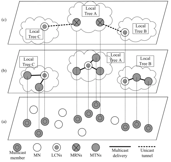
(27) maintain the connection to another local tree by discovering the closest multicast group member which does not belong to this local tree. An LCN will select the closest member in another local tree as an MRN. Therefore, an MRN is associated with an LCN of another local multicast tree. MTNs are the mobile nodes which do not belong to LCNs, and MRNs are parts of MTNs. Different types of nodes have different ways to communicate with each other. Transmissions between LCNs and MRNs use unicast tunnels to encapsulate multicast packets. Transmissions in a local tree are via multicasting. The architecture of our HOMRP and its packet delivery is shown in Figure 2. The bottom level (a) of Figure 2 shows the multicast group members in MANETs. The construction of local multicast trees in each dense area for multicast delivery is shown as the middle level (b). The transmissions between local multicast trees are by unicast tunnels and is shown as the top level (c). It is essential to let a multicast group member realize what type of nodes it belongs to.. 11.
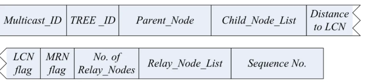
(28) Figure 2:The architecture of HOMRP and its packet delivery: (a) multicast group members distribution, (b) local multicast tree formation, and (c) unicast tunnel establishment.. 3.3 Multicast Connection Table This protocol uses a multicast connection table (MCT) for maintenance of multicast routes. Here we define the MCT as shown in Table 2. The Multicast ID field records the multicast group ID. TREE_ID is the identification number of the current local multicast tree. Parent_Node and Child_Node_List are the current parent node and child nodes in the local multicast tree. Distance to LCN is the distance to the current LCN of local tree. LCN flag and MRN flag are flags to mark if this node is an LCN or an MRN, respectively. If LCN flag= true, Parent_Node 12.
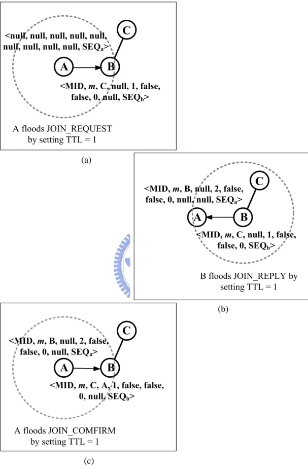
(29) records the associated MRN. If MRN flag = true, Relay_Node_List records the associated LCN. No. of Relay_Node records numbers of current related LCNs. Sequence No. records the sequence number of the last JOIN_REQUEST. Table 2:Multicast connection table entry.. 3.4 Member Discovery and Route Selection Each multicast group member needs to discover other nearby members periodically by sending JOIN_REQUEST messages. In order to reduce control overheads for communications, similar to FGMP [6], we assign a value to TTL to limit the scope of flooding in HOMRP. We adopt a two-level flooding scheme for controlled flooding. This scheme defines two ranges, 1 hop and TTLmax. The value of TTLmax hop is defined by implementation. The format of JOIN_REQUEST is shown in Table 3. The new field of JOIN_REQUEST, level of flooding, records an initial value of TTL. Table 3:JOIN_REQUEST packet format.. We. use. <Multicast_ID. (MID),. TREE_ID,. Parent_Node. (PRN),. Child_Node_List, Distance to LCN, LCN flag, MRN flag, No. of Relay_Nodes, Relay_Node_List, Sequence No. (SEQ)> to denote an MCT entry. Figures 3 and 4 illustrate the procedure of member discovery in two different situations. Figure 3(a) illustrates a mobile node A initiating to join a multicast group. B and C are multicast 13.
(30) group members in the same local multicast tree with TREE_ID = m. C is the LCN of this local multicast tree. The Parent_Node of B is C. A needs to flood a JOIN_REQUEST. It sets TTL = 1 to deliver this packet and starts a short timer to wait for JOIN_REPLY, as shown in Figure 3(a). If A received JOIN_REPLY after timer expiration, it will not re-flood the control messages. Instead, A sets TTL = TTLmax to deliver JOIN_REQUEST again and starts a long timer to wait for JOIN_REPLYs, as shown in Figure 4(a). In this way, we can reduce the flooding range when group members are in close proximity and avoid the flooded packets being forwarded far away. When a multicast group member B receives JOIN_REQUEST from A, B checks TREE_ID in JOIN_REQUEST. If the TREE_ID in JOIN_REQUEST is larger than the TREE_ID in the MCT of B, B will send a JOIN_REPLY to A. The packet format of JOIN_REPLY is as shown in Table 4. If Level of flooding of JOIN_REQUEST is 1, B floods JOIN_REPLY by setting TTL = 1. If not, B sends JOIN_REPLY to A by unicast. If A can receive JOIN_REPLY from B by flooding, we are sure that A and B are within the signal range. Table 4:JOIN_REPLY packet format.. In Figure 3(b), before the timer expires A receives only one JOIN_REPLY from B after it floods JOIN_REQUEST by setting TTL = 1. A updates its MCT as follows: TREE_ID = m, Parent_Node = B and Distance to LCN = 2 shown in Figure 3(b) and floods JOIN_CONFIRM to B by setting TTL = 1. The packet format of JOIN_CONFIRM packets is shown in Table 5. When B receives JOIN_CONFIRM from A, B updates its MCT and adds A to Child_Node_List, as shown in Figure 3(c). 14.
(31) In addition, if A receives more than one JOIN_REPLY, A chooses a suitable one to be the Parent_Node by the following precedence order. First, A selects a node which belongs to the same local multicast tree with A. Second, A selects a node that does not have a smaller TREE_ID than that of A. Third, A selects a node that has a smaller value of Distance to LCN. Last, A selects a node randomly. Table 5:JOIN_COMFIRM packet format.. If A receives only one JOIN_REPLY from B after it floods JOIN_REQUEST by setting TTL = TTLmax before the timer expires, A updates its MCT and unicasts JOIN_CONFIRM to B, as shown in Figure 4(b). A marks itself as an LCN, and sets Parent_Node = B, TREE_ID = m+1, and Distance to LCN = 0. When B receives JOIN_CONFIRM from A, B updates its MCT, as shown in Figure 4(c). B adds A to Relay_Node_List and sets No. of Relay_Nodes to 1. In addition, if A receives more than one JOIN_REPLY, A chooses a suitable one to be the Parent_Node by the following precedence order. First, A selects a node that has a smaller TREE_ID than that of A. Second, A selects a node has a smaller No. of Relay_Node. Last, A selects a node that replied earlier. However, there is a situation that A can select any node without considering the value of TREE_ID. We will discuss this situation in section 3.5. There is a special case. If A did not receive any response after flooding JOIN_REQUEST by setting TTL = TTLmax, we can conclude that A is the first group member. Then A sets itself as an LCN with TREE_ID = 1. Algorithm 1 shows the procedure of modifying the MCT during member discovery. The member discovery flowchart based on Algorithm 1 is shown Figure 5. 15.
(32) (a). (b). (c) Figure 3:Member discovery within the signal range: (a) node A floods JOIN_REQUEST by setting TTL = 1, (b) node B sends JOIN_REPLY by setting TTL = 1. If A selects B as Parent_Node, A updates its MCT, and (c) node A sends JOIN_CONFIRM to B. B updates its MCT. 16.
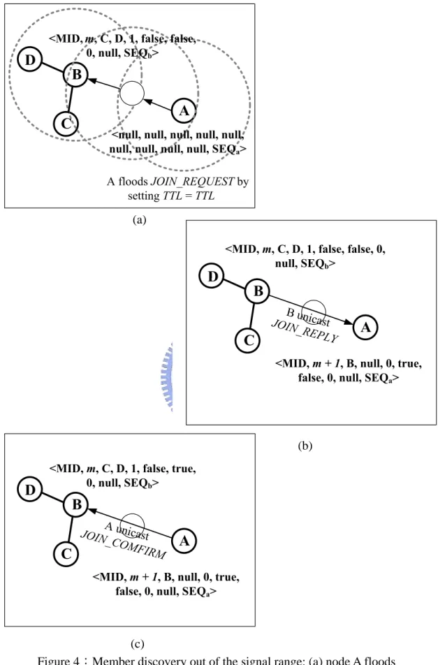
(33) (a). (b). (a). (c) Figure 4:Member discovery out of the signal range: (a) node A floods JOIN_REQUEST by setting TTL = 1, (b) node B sends JOIN_REPLY by unicast. If A selects B as Parent_Node, A updates its MCT, and (c) node A sends JOIN_CONFIRM to B by unicast. B updates its MCT. 17.
(34) Procedure: Sending_JOIN_REQEST { Start a short timer; Sets Level of flooding of JOIN_REQUEST = 1, floods JOIN_REQUEST by setting TTL = 1; If the timer expires, and did not receive JOIN_REPLY { Start a long timer; Sets Level of flooding of JOIN_REQUEST = TTLmax, and floods JOIN_REQUEST by setting TTL = TTLmax,; if the long timer expires, did not receive JOIN_REPLY LCN flag = true; TREE_ID = 1; Distance to LCN = 0; } } Procedure: Receiving_JOIN_REQEST { if TREE_ID <= TREE_ID of JOIN_REQUEST { if Level of flooding of JOIN_REQUEST == 1 floods JOIN_REPLY by setting TTL=1; else sends JOIN_REPLY to the sender of JOIN_REQUEST by unicast; } } Procedure: Receiving_JOIN_REPLY_by_Flooding { if receives only one JOIN_REPLY { TREE_ID = TREE_ID in the JOIN_REPLY; Parent_Node = the replied one; Distance to LCN = (Distance to LCN of JOIN_REPLY) + 1; } else { Select one to be Parent_Node; TREE_ID = TREE_ID of the selected one; Distance to LCN = (Distance to LCN of the selected one) +1; } floods JOIN_COMFIRM by setting TTL=1; } Procedure: Receiving_JOIN_REPLY_by_unicast { LCN=true; if receives only one JOIN_REPLY { TREE_ID = TREE_ID of the replied one; Parent_Node = the replied one; Distance to LCN = (Distance to LCN of the replied one) + 1; } else { Select one to be Parent_Node; TREE_ID = TREE_ID of Parent_Node; Distance to LCN = (Distance to LCN of the selected one) + 1; } Sends JOIN_COMFIRM to the selected one by unicast; } Procedure: Receiving_JOIN_CONFIRM_by_Flooding { if Parent_Node of JOIN_CONFIRM == the received node add the sender of JOIN_CONFIRM to Child_Node_List; } Procedure: Receiving_JOIN_CONFIRM_by_unicast { if Parent_Node of JOIN_CONFIRM == the received node { MRN flag = true; add the sender of JOIN_CONFIRM to Relay_Node_List; No. of Relay_Node = No. of Relay_Node + 1; } }. Algorithm 1:Procedures for member discovery.. 18.
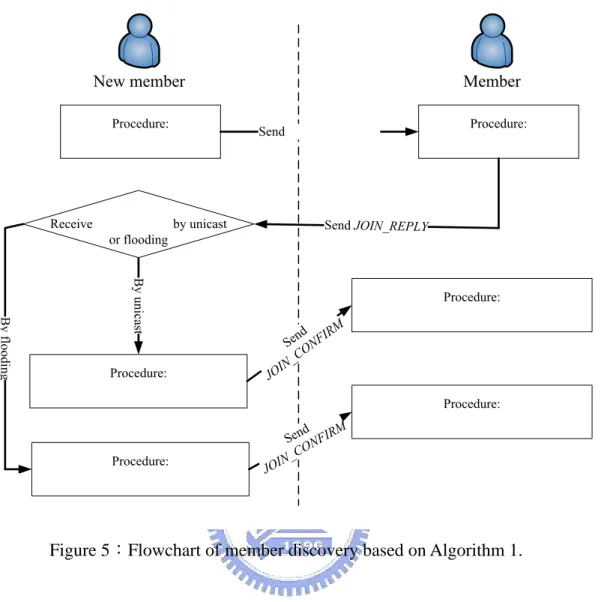
(35) Figure 5:Flowchart of member discovery based on Algorithm 1.. 3.5 Efficient Routes In order to avoid looping routes between local trees in HOMRP, we assign each local multicast tree a tree ID. The TREE_ID of the first local tree is set to one. The TREE_ID of a new local multicast tree will depend on the associated local multicast tree. For example, Node J sets itself as an LCN to initiate a new local multicast tree and J selects a local multicast tree with TREE_ID = N to associate. The TREE_ID of J is N + 1. If there is an MRN in the local multicast tree of J, J can only select local multicast trees with a smaller TREE_ID to associate in the next member discovery period. In this way, the connections of local multicast trees can be loop-free by assigning TREE_ID to each local multicast tree. Otherwise, J can select the first 19.
(36) reply one to associate without considering the value of TREE_ID; this lets J select a better route for unicast tunnels.. 3.6 Local Multicast Tree Consolidation Mobile nodes in MANETs may have mobility. A local tree may become close to another local tree at a distance of one hop due to mobility, then we can consolidate the two trees into one. In HOMRP, we design the packet format of TREE_CONSOLIDATION, as shown in Table 6 for tree consolidation. We assume that an MTN C with TREE_ID = N discovers an MTN B with TREE_ID = M, and A and E with TREE_ID = N within its signal range as shown in Figure 6(a). In Figure 6(b), C sets its Parent_Node as B, sets TREE_ID = M, sets Distance to LCN as Distance to LCN of B adds one, and sends JOIN_CONFIRM to B and the TREE_COSOLIDATION message to other MTNs which belong to the same local tree of B, if M is smaller than N. Otherwise, B updates its MCT and sends TREE_CONSOLIDATION to other MTNs which belong to the same local tree. When MTNs receive the TREE_COSOLIDATION messages, they update their MCTs,. as. shown. Figure. TREE_CONSOLIDATION. 6(c).. message... They The. modify. procedure. and of. MTNs. TREE_CONSOLIDATION is shown in Algorithm 2. Table 6:TREE_CONSOLIDATION packet format.. 20. forward. the. receiving.
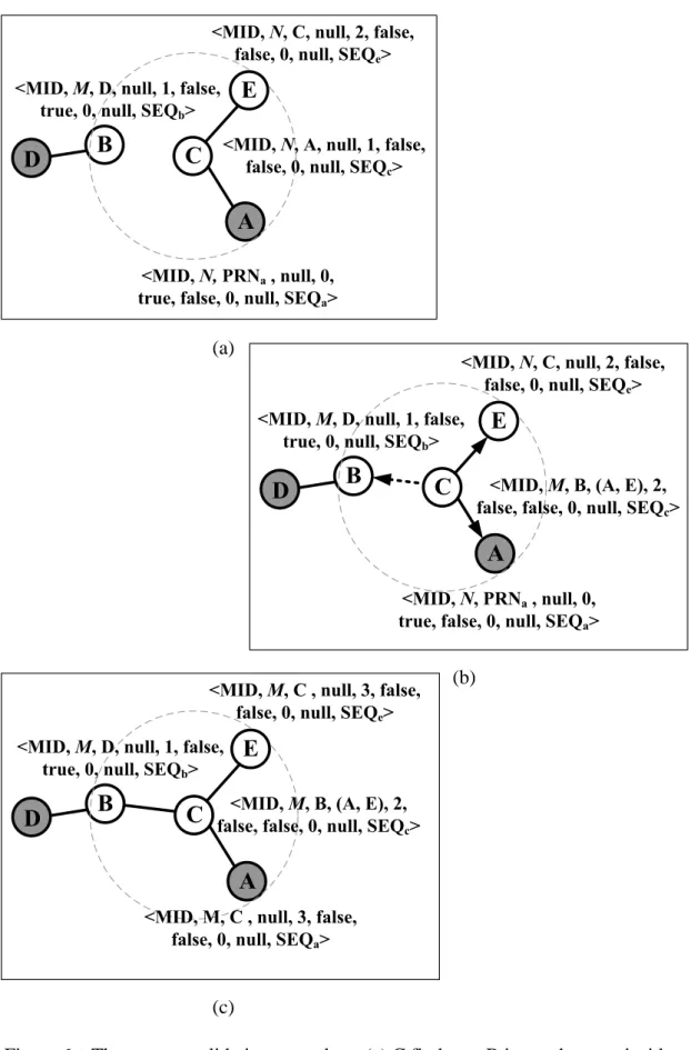
(37) (a). (b) (b). (c) Figure 6:The tree consolidation procedure: (a) C finds out B in another tree inside its signal range; (b) The dotted arrowhead shows that C updates its MCT and and sends JOIN_CONFIRM to B. And C sends TREE_CONSOLIDATION to A and E; (c) A, B and E update their MCTs. 21.
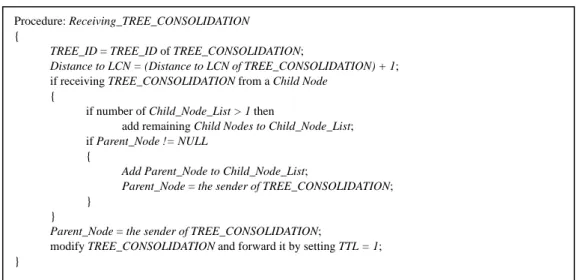
(38) Procedure: Receiving_TREE_CONSOLIDATION { TREE_ID = TREE_ID of TREE_CONSOLIDATION; Distance to LCN = (Distance to LCN of TREE_CONSOLIDATION) + 1; if receiving TREE_CONSOLIDATION from a Child Node { if number of Child_Node_List > 1 then add remaining Child Nodes to Child_Node_List; if Parent_Node != NULL { Add Parent_Node to Child_Node_List; Parent_Node = the sender of TREE_CONSOLIDATION; } } Parent_Node = the sender of TREE_CONSOLIDATION; modify TREE_CONSOLIDATION and forward it by setting TTL = 1; }. Algorithm 2:Procedure when receiving TREE_CONSOLIDATION message.. 3.7 Member Disjoin and Fast Recovery We assume an MTN W disjoins the group; it requires sending DISJOIN_REQ to its Parent_Node X. X sends DISJOIN_RELAY_REQ by unicast to the nodes of Child_Node_List and Relay_Node_List of the disjoining member and starts a timer. The packet format of DISJOIN_REQ messages is shown in Table 7 After the time expiration, X sends a DISJOIN_ACK to W. The MTNs which receive DISJOIN_RELAY_REQ change their MCT and reply a DISJOIN_RELAY_REP to X. When X receives DISJOIN_RELAY_REP, X updates its MCT. The detail of modifying MCT for member disjoin is shown in Algorithm 3. According to Algorithm 3, we draw the member disjoin flowchart, as shown Figure 7. Table 7:DISJOIN_REQ packet format.. 22.
(39) Procedure: Receiving_DISJOIN_REQ { Sends DISJOIN_RELAY_REQ to the nodes in Child_Node_List and Relay_Node_List of DISJOIN_REQ; Start a timer; After timer expiration, sends DISJOIN_ACK to the sender of DISJOIN_RELAY_REQ; } Procedure: Receiving_DISJOIN_RELAY_REQ { TREE_ID = TREE_ID + 1; LCN flag = true; Distance to LCN = 0; Parent_Node = sender of DISJOIN_RELAY_REQ; Sends DISJOIN_RELAY_REP to Parent_Node; } Procedure: Receiving_DISJOIN_RELAY_REP { Adds sender of DISJOIN_RELAY_REP to Relay_Node_List; No. of Relay_Node = No. of Relay_Node + 1; MRN flag = true; } Procedure: Receiving_DISJOIN_ACK { Clean MCT of the disjoining group; }. Algorithm 3:Procedures for member disjoin.. DISJOIN_REQ Parent_Node Receiving_DISJOIN_REQ. Receiving_DISJOIN_RELAY_REQ. Receiving_DISJOIN_RELAY_REP. Receiving. Figure 7:Flowchart for member disjoin based on Algorithm 3.. 23.
(40) 3.8 Packet Delivery HOMRP supports packet delivery from multiple sources to multiple receivers. There is only one route structure for each multicast group. All routes from a parent to children are at a distance of one hop in a local multicast tree. The purpose to record the parent node and child nodes is to let a group member know when it needs to forward multicast packets in a local multicast tree. Therefore, a local multicast tree in HOMRP is a bi-directional tree. In addition, an LCN can send packets to or receive packets from its MRN. An MRN can send packets to or receive packets from its associated LCNs. Therefore, the transmissions between local trees are also bi-directional. HOMRP is a bi-directional multicast protocol; any member can become a source whenever it needs to send data to the group without requiring constructing a new multicast route. Since HOMRP is bi-directional, each multicast group member needs to maintain a message cache to record the sequence number of a packet from each sender to avoid packet duplication. In HOMRP, communications inside a local multicast tree adopt multicasting and communications between local multicast trees adopt unicast tunnels to encapsulate multicast packets, as shown in as Figure 2.. 3.9 Route Maintenance Each multicast group member needs to discover nearby members periodically in HOMRP. We have defined three types of multicast group members: LCN, MRN and MTN. Different types of multicast group members have different periods for member discovery. An LCN has a long period and an MTN has a short period. This is because the transmissions for an LCN are performed by unicast tunnels. However, 24.
(41) the transmissions for an MTN are done by multicasting. Therefore, an MTN needs to update route information more often. Route maintenance of different type of nodes using different update periods is efficient for reducing control overhead. This concept is similar to the Fisheye state routing protocol [13]. Mobile nodes in the Fisheye state routing protocol use different update periods for different distances. This is based on that the smallest scope is propagated with highest frequency. That is, a long update period is for discovering a far away node and a short update period is for discovering a nearby node.. 3.10 Data Structures for Implementation Multicast group members in HOMRP need to maintain the following data structures: z. Multicast Connection Table (MCT): Each multicast group member stores the relationship of its parent node, children nodes and relay nodes in this table.. z. Multicast Relay Routing Table: All multicast group members need to maintain this table. This table is expended from MCT. This table records if an MTN needs to forward multicast packets by multicasting or not when it receives multicast packets. If an MTN only has a parent node, or has one child node without a parent node, it will not forward the multicast packets when it receives multicast packets. If an LCN has more than two children nodes, it needs to forward multicast packets.. z. Unicast Relay Routing Table: This table is expended from MCT. LCNs and MRNs maintain this table for recording those group members who need to be 25.
(42) forwarded multicast packets by unicast tunnels. An LCN records its Parent_Node in this table. An MRN records the Relay_Node_List in this table. z. Message Cache: This is maintained by each multicast group member to detect duplicated packets.. 26.
(43) Chapter 4 SIMULATION AND DISCUSSION 4.1 Simulation Environment HOMRP was simulated using the Global Mobile Simulation (GloMoSim) [15]. The GloMoSim is a scalable simulation environment for wireless network systems using the parallel discrete-event simulation capability provided by PARSEC [16]. Our simulation models a wireless network with 50 hosts placed randomly within a 1000 m × 1000 m area. The movements of hosts is based on the random-waypoint model. The MAC protocol is the IEEE 802.11 with 2 Mbits/sec channel capacity. The simulation time is 600 seconds. The pause time is 10 seconds. Each node moves with speed of 0, 10, 20, 30, 40 or 50 meters per second. The constant bit rate (CBR) is assigned for data flows and the payload is 512 bytes. The adopted unicast routing protocol is dynamic source routing (DSR) [17]. The simulation parameters are listed in Table 8.. 27.
(44) Table 8:Simulation Parameters. ×. 4.2 Evaluation of Different Group Sizes In this setion, we simulated the performances of HOMRP with group sizes of 5, 10, 20 and 30. In this experiment, there were 5 sources. Figure 8 illustrates the packet delivery ratio of HOMRP under different group sizes. All cases of different group sizes perform well without mobility. As the mobility speed increases, the multicast group with smaller group sizes, e.g. 5 and 10, performed worse, because the multicast packets were transmitted by using unicast tunnels. The performance of larger group sizes, e.g. 20 and 30, were better than that of the smaller ones under high mobility. This is because the larger the group size is, the denser the placement of the group members is, and more local multicast trees can be created. It is efficient to deliver multicast packets by multicasting. The average number of control packets transmitted per data packet delivered (control overhead) versus mobility speed is shown in Figure 9. The control overhead increases with the mobility speed, because the probability of sending TREE_CONSOLIDATION becomes high at high mobility speeds. In addition, a 28.
(45) smaller multicast group had a higher control overhead. Figure 10 shows the average end-to-end delay per data packet delivered. The multicast group with smallrt group sizes, i.e. 5 and 10, had higher end-to-end delay, because a large percentages of packet delivery were transmitted by unicast tunnels. Using unicast tunnels increase end-to-end delay. On the other hand, the multicast group with larger group sizes had lower end-to-end delay. This is because a large percentage of packet deliveries were transmitted by multicasting.. 1 Group Size 30 Group Size 20 Group Size 10 Group Size 5. 0.99 Packet delivery ratio. 0.98 0.97 0.96 0.95 0.94 0.93 0.92 0.91 0.9 0. 10. 20 30 Mobility speed (m/sec). Figure 8:Packet delivery ratio as a function of mobility speed.. 29. 40. 50.
(46) 0.3. 0.2. 0.15. Group Size 5 Group Size 10 Group Size 20 Group Size 30. 0.1 0. 10. 20 30 Mobility speed (m/sec). 50. 40. Figure 9:Control overhead as a function of mobility speed.. 0.9 0.8 End-to-end delay (sec). Control overhead. 0.25. 0.7 0.6 0.5 0.4 0.3 Group Size 5 Group Size 10 Group Size 20 Group Size 30. 0.2 0.1 0 0. 10. 20. 30. 40. Mobility speed (m/sec) Figure 10:End-to-end delay as a function of mobility speed.. 30. 50.
(47) 4.3 Comparison with Other Approaches In this section, we compare HOMRP to an efficient overlay protocol, AMRoute [11], and a high performance meshed-based protocol, ODMRP [5]. Both AMRoute and ODMRP are IETF Internet Draft. There are 5 sources and each node’s mobility speed is 20 meters/second. The group size is 20. Figure 11 shows the packet delivery ratio as a function of mobility speed among different approaches. ODMRP is shown to have the highest packet delivery ratio even in high mobility, because ODMRP uses the mesh topology. If one route is fail, there is possible another route to delivery packet successfully. However, ODMRP used more system resources such as bandwidth than the other two approaches. AMRoute is good with no mobility, but it has very low packet delivery ratio in high mobility. Its packet delivery ratio is getting worse as the mobility speed increases. One reason is that AMRoute may build inefficient share trees and has the problem of loop paths. Route maintenance in HOMRP is initiated by each group member. Each member only maintains those members that are close to it, so each member knows available links to other members clearly. Therefore, compared to AMRoute, HOMRP increases 50% packet delivery ratio. It has slightly lower packet delivery ratio at high mobility speeds compared to ODMRP, because the performance of the unicast protocol decreases at high mobility speeds. Figure 12 illustrates control overhead as a function of mobility speed among different approaches. ODMRP has the highest control overhead, because it needs to maintain the forwarding group members and transmit JOIN_TABLE during the member discovery period [5]. Since AMRoute only creates one multicast tree per multicast group for multiple sources, AMRoute is more efficient than ODMRP. We. 31.
(48) can see HOMRP has the lowest control overhead. This is only multicast group members need to maintain multicast routes in HOMRP. A multicast member only needs to maintain those members that are close to it, but not the whole members. Therefore, the sizes of exchanged control packets can be reduced. The two-level flooding scheme also reduces the range of flooding to avoid unnecessarily control packets. Those contribute to low control overhead. In sum, HOMRP reduces 18% control overhead compared to ODMRP. As to AMRoute, HOMRP reduce 12% control overhead than AMRoute. Figure 13 illustrates the end-to-end delay per data packet delivered. All packets transmissions in AMRoute are by unicast tunnels, so that AMRoute has the worst end-to-end delay. ODMRP maintains forwarding group members for packet forwarding. This increases the speed of packet delivery. HOMRP has higher end-to-end delay than ODMRP, because some parts of transmissions in HOMRP are by unicast tunnels. Since HOMRP transmits packets by multicasting in local trees, it reduces 9% end-to-end delay compared to AMRoute.. 32.
(49) 100. Packet delivery ratio (%). 90 80 70 60 ODMRP HOMRP AMRoute. 50 40 0. 10. 20 30 Mobility speed (m/sec). 40. 50. Figure 11:Packet delivery ratio as a function of mobility speed among different approaches.. 0.35. Control overhead. 0.3 0.25 0.2 0.15 0.1 ODMRP AMRoute HOMRP. 0.05 0 0. 10. 20 30 Mobility speed (m/sec). 40. Figure 12:Control overhead as a function of mobility speed among differnent approaches. 33. 50.
(50) 0.5 0.45 End-to-end delay (sec). 0.4 0.35 0.3 0.25 0.2 0.15 AMROUTE AOMRP ODMRP. 0.1 0.05 0 1. 2. 3. 4. 5. Mobility speed (m/sec) Figure 13:End-to-end delay as a function of mobility speed among different approaches.. 34. 6.
(51) Chapter 5 CONCLUSIONS AND FUTURE WORK 5.1 Concluding Remarks The proposed hybrid overlay multicast routing protocol (HOMRP) has been presented in this thesis. It integrates multicasting and unicast tunnels for packet transmissions. It creates multiple local multicast trees where each pair of parent node and child node is at a distance of one-hop. It uses multicasting to deliver multicast packets in local multicast trees to provide efficient data forwarding. Unicast tunnels are used for transmitting packets between local multicast trees. It avoids looping routes between local multicast trees by assigning each local tree a tree ID. Two-level flooding is used for member discovery, which limits the value of TTL in a packet to reduce the control overhead of flooding. Due to the dynamic network topology in MANETs, HOMRP uses a tree consolidation scheme for highly efficient multicast delivery. In addition, HOMRP does not require to use any specific unicast routing protocol; hence it can operate with any unicast routing protocols. In addition, each multicast group only needs to maintain a route structure for multiple sources; this is efficient for route maintenance.. 35.
(52) Simulation results have shown that HOMRP have a higher packet delivery ratio, lower control overhead and lower packet delay as the group size become larger. In addition, it also performs well with small group sizes, because of the high performance of the unicast routing protocol. In sum, HOMRP improves 50% packet delivery ratio and reduces 9% end-to-end packet delay compared to AMRoute. In addition, HOMRP provides high packet delivery ratio which is close to ODMRP and reduces 18% control overhead compared to ODMRP. Therefore, our HOMRP is an efficient multicast routing protocol, which is very suitable for a large multicast group with a large number of multiple sources (senders).. 5.2 Future Work HOMRP is a hybrid overlay multicast routing protocol based on a unicast routing protocol. We adopt DSR as the underlying unicast protocol for HOMRP. There are other unicast routing protocols that have been proposed for MANETs, such as AODV, DSDV and OLSR. We will evaluate the performance of HOMRP with different unicast routing protocols. By this evaluation, we can select a more suitable unicast routing protocols to further improve the performance of HOMRP. Since HOMRP is efficient for a large multicast group with a large number of multicast sources (senders), we can use HOMRP to implement multicast applications with multiple sources, such as real time games with multiple players or instant video stream exchanging with multiple senders. This deserves for further study.. 36.
(53) Bibliography [1] Carlos de Morais Cordeiro, Hrishikesh Gossain, and Dharma Agrawal, “Multicast over Wireless Mobile Ad Hoc Networks: Present and Future Directions,” IEEE Network, Volume: 17 Issue: 1, pp. 52 -59, Jan.-Feb. 2003.. [2] Li Xiao, A. Patil, Yunhao Liu and L.M. Ni, “Prioritized Overlay Multicast in Mobile Ad Hoc Environments,” IEEE Computer, Volume: 37 Issue: 2, pp. 67 -74, Feb. 2004.. [3] E. M. Royer and C. E. Perkins, “Multicast Operation of the Ad Hoc On-Demand Distance Vector Routing Protocol,” in Proc. of ACM MOBICOM, Aug. 1999, pp. 207 - 218. [4] C.W. Wu, Y.C. Tay, and C.-K. Toh, “Ad Hoc Multicast Routing Protocol Utilizing Increasing id-numberS (AMRIS) Functional Specification,” Internet Draft, Nov. 1998.. [5] Sung Ju Lee, William Su, and Mario Gerla, “On-Demand Multicast Routing Protocol,” in Proc. of IEEE WCNC, Sept. 1999, pp. 1298 - 1302.. 37.
(54) [6] C.-C. Chiang, M. Gerla, and L. Zhang, “Forwarding Group Multicast Protocol (FGMP) for Multihop, Mobile Wireless Networks,” ACM/Baltzer Journal of Cluster Computing: Special Issue on Mobile Computing, Volume: 37, pp. 187–96, 1998.. [7] Subir Kumar Das, B. S. Manoj, and C. Siva Ram Murthy, “A Dynamic Core based Multicast Routing Protocol for Ad hoc Wireless Networks,” in Proc. of ACM MobiHoc, June 2002.. [8] Yao Zhao, Leirning Xu, and Meilin Shi, “On-Demand Multicast Routing Protocol with Multipoint Relay (ODMRP-MPR) in Mobile Ad-Hoc Network,” in Proc. of International Conference on ICCT , Volume: 2, April 2003, pp. 1295 - 1300.. [9] Thomas Heide Clausen and Philippe Jacquet, “Optimized Link State Routing Protocol,” in Proc. of. International Conference on INMIC, Dec. 2001, pp.. 62-68.. [10] J.J. Garcia-Luna-Aceves and E.L. Madruga, “The Core-Assisted Mesh Protocol,” IEEE Journal on Selected Areas in Communications, vol. 17, no. 8, pp. 1380 -1394, Aug. 1999.. [11] E. Bommaiah, M. Lui, A. McAuley, and R. Talpade, “AMRoute: Adhoc Multicast Routing Protocol,” Internet Draft, Aug. 1998.. 38.
(55) [12] Chao Gui and Prasant Mohapatra, “Efficient Overlay Multicast for Mobile Ad Hoc Networks,” in Proc. of IEEE WCNC, March 2003, pp. 1118 - 1123. [13] Guangyu Pei, M. Gerla, and Tsu-Wei Chen, “Fisheye State Routing: A Routing Scheme for Ad Hoc Wireless Networks,” in Proc. of ICC, Volume: 1, June 2000, pp. 70 -74.. [14] A. Laouiti, A. Qayyum and L. Viennot, “Multipoint Relaying: An Efficient Technique for Flooding in Mobile Wireless Networks,” in Proc. of 35th Annual Hawaii International Conference on System Sciences (HICSS'2002), April 2003, pp. 1295 - 1300.. [15] UCLA Parallel Computing Laboratory and Wireless Adaptive Mobility Laboratory, “GloMoSim: A Scalable Simulation Environment for Wireless and Wired. Network. Systems”,. [online].. Available:. http://pcl.cs.ucla.edu/projects/domains/glomosim.html.. [16] R. Bagrodia, R. Meyer, M. Takai, Y. Chen, X. Zeng, J. Martin, and H. Y. Song, “PARSEC: A Parallel Simulation Environment for Complex Systems,” IEEE Computer, Volime. 31, October 1998, pp. 77 - 85.. [17] J.Broch, D. Johnson, and D. Maltz. “The Dynamic Source Routing Protocol for Mobile. Ad. Hoc. http://www.ietf.org/internet-drafts/draft-ietfmanet-dsr-03.txt, Draft, Oct. 1999. 39. Networks,” IETF. Internet.
(56) [18] Sung-Ju Lee, William Su, Julian Hsu, Mario Gerla, and Rajive Bagrodia, “A Performance Comparison Study of Ad Hoc Wireless Multicast Protocols,” in Proc. of INFOCOM, Mar. 2000, pp. 565-74.. [19] Josh Broch, David A. Maltz, David B. Johnson, Yih-Chun Hu, and Jorjeta Jetcheva, “A Performance Comparison of Multihop Wireless Ad Hoc Network Routing Protocols,“ in Proc. of IEEE/ACM MOBICOM ’98, Oct. 1998, pp. 85-97.. [20] IEEE Standards Department, Wireless LAN Medium Access Control (MAC) and Physical Layer (PHY) Specifications, Standard 802.11, 1999.. [21] Larry L. Peterson and Bruce S. David, “Computer Networks: A systems Approach, Second Edition,” Morgan Kaufmann Publishers, 2000.. [22] T. Ohta, S. Inoue and Y. Kakuda, “An Adaptive Multihop Clustering Scheme for Highly Mobile Ad Hoc Networks,” Autonomous Decentralized Systems, pp. 293 – 300, April 2003.. [23] V. Devarapalli and D. Sidhu, "MZR: A Multicast Protocol for Mobile Ad Hoc Networks," in Proc. of IEEE ICC, Jun. 2001, pp. 886 - 891.. [24] Xiaofeng Zhang and L. Jacob, “Multicast Zone Routing Protocol in Mobile Ad Hoc Wireless Networks,” in Proc. of IEEE International Conference on Local Computer Networks, Oct. 2003, pp. 150 – 159.. 40.
(57) [25] L. Ji, and M. S. Corson, “Differential Destination Multicast — A MANET Multicast Routing Protocol for Small Groups,” in Proc. of INFOCOM, 2001, pp. 1192 – 02.. [26] Chun-Chieh. Huang,. Ruay-Shiung. Chang. and. Ming-Huang. Guo,. “Weight-based Clustering Multicast Routing Protocol for Mobile Ad Hoc Networks,” in Proc. of IEEE WCNC, Volume: 2 , March 2003, pp. 1112 - 1117.. 41.
(58)
數據
![Table 1:Comparison of multicast routing protocols for MANETs [1].](https://thumb-ap.123doks.com/thumbv2/9libinfo/8743561.204534/23.892.178.705.159.705/table-comparison-multicast-routing-protocols-manets.webp)
+7
相關文件
Al atoms are larger than N atoms because as you trace the path between N and Al on the periodic table, you move down a column (atomic size increases) and then to the left across
Reading Task 6: Genre Structure and Language Features. • Now let’s look at how language features (e.g. sentence patterns) are connected to the structure
Wang, Solving pseudomonotone variational inequalities and pseudocon- vex optimization problems using the projection neural network, IEEE Transactions on Neural Networks 17
Define instead the imaginary.. potential, magnetic field, lattice…) Dirac-BdG Hamiltonian:. with small, and matrix
附錄 2:在 Windows XP 中將 Tera Term 設定為預設 Telnet 用戶端.. 附錄
• elearning pilot scheme (Four True Light Schools): WIFI construction, iPad procurement, elearning school visit and teacher training, English starts the elearning lesson.. 2012 •
(Another example of close harmony is the four-bar unaccompanied vocal introduction to “Paperback Writer”, a somewhat later Beatles song.) Overall, Lennon’s and McCartney’s
n SCTP ensures that messages are delivered to the SCTP user in sequence within a given stream. n SCTP provides a mechanism for bypassing the sequenced
