1418 IEEE TRANSACTIONS ON ANTENNAS AND PROPAGATION, VOL. 61, NO. 3, MARCH 2013
TABLE III
THESIMULATED(HFSS)VS. MEASURED(M) RESULTS FOR THEDIRECTIONS ANDREALIZEDGAIN OF THEFORWARD ANDBACKWARDBEAMS OF THE
PROPOSEDANTENNA IN THE PLANE AT5.3, 5.5,AND5.8 GHz
the antenna bandwidth. The maximum difference between the beams’ maxima is a crucial criterion in multi-beam antenna design. The effi-ciency obtained from both beams is calculated and found to be greater than 95%. The realized gain and estimated efficiency for each beam are similar to the single broadside beam of the conventional U-slot antenna operating at the mode [10].
IV. CONCLUSION
A U-slot microstrip antenna operating at a higher order mode has been proposed and investigated. The antenna has 11.3% bandwidth (5.17–5.81 GHz) and exhibit dual radiation beams. The beams are di-rected around at the center frequency, and both beams’ squint is less than 4 within the antenna bandwidth. Realized gain of the for-ward beam is 7.92 dBi at the center frequency, whereas it is 5.94 dBi for the backward beam. The difference between both beams’ maxima is less than 2 dBi across the entire bandwidth. The proposed design is a desirable candidate for stationary terminals of various indoor wireless communication networks.
REFERENCES
[1] P. Driessen, “Gigabit/s indoor wireless systems with directional an-tennas,” IEEE Trans. Commun., vol. 44, no. 8, pp. 1034–1043, Aug. 1996.
[2] Y. M. Tao and G. Y. Delisle, “Lens-fed multiple beam array for mil-limeter wave indoor communications,” in Proc. IEEE AP-S Int. An-tenna and Propag. Symp. Digest, Jul. 1997, pp. 2206–2209. [3] K. Li, M. Ingram, and E. Rausch, “Multibeam antennas for indoor
wire-less communications,” IEEE Trans. Comm., vol. 50, no. 2, Feb. 2002. [4] K. Carver and J. Mink, “Microstrip antenna technology,” IEEE Trans.
Antennas Propag., vol. 29, no. 1, pp. 2–24, 1981.
[5] Y. T. Lo, D. Solomon, and W. F. Richards, “Theory and experiment on microstrip antennas,” IEEE Trans. Antennas Propag., vol. 27, no. 2, pp. 137–145, Mar. 1979.
[6] J. R. James and P. S. Hall, Handbook of Microstrip Antennas. London, U.K.: Peter Peregrinus Ltd, 1989, p. 111.
[7] K. F. Lee and K. M. Luk, Microstrip Patch Antennas. London, U.K.: Imperial College Press, 2010.
[8] T. Huynh and K. F. Lee, “Single-layer single-patch wideband mi-crostrip antenna,” Electron. Lett., vol. 31, no. 16, pp. 1310–1312, Aug. 1995.
[9] K. M. Luk, C. L. Mak, Y. L. Chow, and K. F. Lee, “Broadband microstrip patch antenna,” IET Electron. Lett., vol. 34, no. 15, pp. 1442–1443, 1998.
[10] K. F. Lee, S. S. Yang, A. Kishk, and K. M. Luk, “The versatile U-slot patch antenna,” IEEE Antennas Propag. Mag., vol. 52, no. 1, pp. 71–88, February 2010.
[11] C. A. Balanis, Antenna Theory Analysis and Design, 2nd ed. Hoboken, NJ, USA: Wiley-Interscience, 2005, p. 814.
[12] Ansoft HFSS ver. 13, Ansoft Corporation. Canonsburg, PA, USA, 2011.
Broadband CPW-Fed Circularly-Polarized Slot Antenna With an Open Slot
Jen-Yea Jan, Chien-Yuan Pan, Kuo-Yung Chiu, and Hua-Ming Chen
Abstract—A novel broadband CPW-fed circularly-polarized slot
an-tenna with an open slot is presented. The broadband circular polarization can be achieved simply by opening the radiation slot at the lower left of slot. From the experimental results, the 3-dB axial-ratio bandwidth can reach as large as 1000 MHz (27% relative to the center frequency of 3700 MHz) which can cover the 3.3–3.8 GHz WiMAX band. In addition, the proposed design has the VSWR impedance bandwidth of 5330 MHz (111% relative to the center frequency of 4795 MHz) which can cover the 2–6 GHz WiMAX band. The proposed antenna also has a peak antenna gain of about 5.3 dBic and gain variations can be less than 1 dBic for frequencies within the CP bandwidth.
Index Terms—Circular polarization, coplanar waveguides (CPW), slot
antennas.
I. INTRODUCTION
The CPW-fed wide slot antennas have received much attention and have been increasingly used because the advantages of wide band-width, low profile, uniplanar geometry and easy integration with mono-lithic microwave integrated circuits. On the other hand, in order for deploying a transmitter and a receiver without causing a polarization mismatch between them and overcoming the multipath fading problem, circular polarization is becoming popular in wireless communications to enhance the system performance. The operation principle of CP an-tennas is to excite two orthogonal modes with equal amplitude but in phase quadrature. It can be achieved by introducing some symmetric or asymmetric perturbations into a wide slot antenna. These perturba-tions can be implemented through from their feeding lines [1]–[4] or slot configurations [5]–[9]. In order to achieve a wide axial ratio (AR) bandwidth further for the CP wide-slot antenna, a number of designs [1], [2], [4], [6], [9]–[12], have been proposed. By implanting a pair of grounded strips [2], [6], [9], [10] or three inverted-L-shaped grounded strips [11], the AR bandwidth can be improved. For a sequential rota-tion array configurarota-tion fed by an asymmetrical [1] or a symmetrical [12] CPW-fed line, the technique by arranging the antenna elements can significantly increase the AR bandwidth. Also, by using a slot com-posed of multiple circular sectors [4], the CP bandwidth of a wide-slot antenna can be improved. However, antenna configurations of these designs are so complex that they lead to a high complexity of antenna design and fabrication.
In this communication, a structurally new and simpler CP slot an-tenna has been proposed. With an open slot introducing an asymmetric perturbation at the lower left of slot, the proposed antenna fed by a wide tuning stub can provide wide circular-polarized and impedance bandwidths. In this design, the 3-dB AR bandwidth can reach as large as 1000 MHz (3.2–4.2 GHz) which is about 27% (relative to the center frequency of 3700 MHz) to cover the 3.3–3.8 GHz WiMAX band. The Manuscript received April 28, 2012; revised September 08, 2012; accepted November 19, 2012. Date of publication December 04, 2012; date of current version February 27, 2013. This work was supported by the National Science Council, Taiwan, R.O.C., under Contract NSC100-2221-E-151-056.
J.-Y. Jan, C.-Y. Pan, and K.-Y. Chiu are with the Department of Electronic Engineering, National Kaohsiung University of Applied Sciences, Kaohsiung 807, Taiwan, R.O.C. (e-mail: [email protected]).
H.-M. Chen is with the Institute of Photonics and Communications, National Kaohsiung University of Applied Sciences, Kaohsiung 807, Taiwan, R.O.C.
Color versions of one or more of the figures in this communication are avail-able online at http://ieeexplore.ieee.org.
IEEE TRANSACTIONS ON ANTENNAS AND PROPAGATION, VOL. 61, NO. 3, MARCH 2013 1421
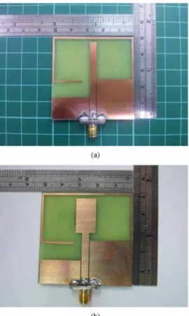
Fig. 8. Photographs of proposed antennas: (a) Antenna 1 as ,
, and in Fig. 1(a). (b) Antenna 4
as , , , and
in Fig. 1(b).
Fig. 9. Measured and simulated results of return loss and axial ratio of Antenna 4 in Table I.
Based on the parametric study, Table I lists the structural parameters and measured CP performances of constructed prototypes. Fig. 7 shows their measured results of return loss and axial ratio (AR). In those con-structed prototypes, Antenna 1 is a slot antenna fed by a straight CPW feeding line as shown in Fig. 1(a). Antennas 2–4 are a slot antenna fed by a wide tuning stub as shown in Fig. 1(b). The photographs of An-tenna 1 and AnAn-tenna 4 are shown in Fig. 8. In Table I and Fig. 7, the
Fig. 10. Simulated magnetic current distributions of Antenna 4 at 3700 MHz by the simulator Ansoft HFSS.
Fig. 11. Measured radiation patterns of Antenna 4 at 3700 MHz.
Fig. 12. Measured and simulated antenna gains and simulated efficiencies of Antenna 4.
measured results show that Antenna 1 protruded by an open slot has the CP operation and an AR bandwidth is about 23.1%. For improving the impedance and 3-dB AR bandwidths, a wide tuning stub at the top of CPW feeding line is used for Antennas 2–4. When suitable dimensions of , and are chosen as shown in Table I, the
impedance bandwidth of Antenna 4 can reach 111% which is larger than that of Antenna 1 (without a wide tuning stub). Also, the 3-dB AR bandwidth of Antenna 4 can reach 27% which is as larger as com-pared with that of Antenna 1. As is decreased from 4.5 to 3.5 mm, both 3-dB AR and impedance bandwidths become smaller. As is larger than 4.5 mm, the CP performance becomes worse. For brevity, its results are not shown in Table I. Fig. 9 shows the measured and sim-ulated results (return loss and CP axial ratio) of Antenna 4 that have a reasonable agreement and the best value of AR can reach about 0.5 dB. In order to perceive that the CP operation can be generated, Fig. 10 shows the magnetic current distribution of Antenna 4 varying with time
1422 IEEE TRANSACTIONS ON ANTENNAS AND PROPAGATION, VOL. 61, NO. 3, MARCH 2013
at 3700 MHz. At , the predominant magnetic current is above the wide tuning stub and is oriented in a direction relative to the axis. At a later time instant with a 90 phase lagging , the principal magnetic current is along the open slot, whose direction is 90 relative to the axis. At , the magnetic cur-rent distribution is just opposite to that at . The magnetic current distribution varying as a function of time in such a fashion can depict the behavior of predominantly right-and left-and CP radiations in the and half spaces, respectively.
Fig. 11 shows the measured and simulated far-field radiation patterns of Antenna 4 in the and planes at the center frequency of 3700 MHz. The far-field radiation patterns have lower AR values around the broadside directions (i.e., directions). They are mainly RHCP for and LHCP for . From Fig. 11, it is seen that measured and simulated results are with reasonable agreement. In 3-dB AR band (3.2–4.2 GHz), the measured and simulated results of peak antenna gain of Antenna 4 are shown in Fig. 12. It is found that the antenna gain has a maximum value of 5.3 dBic with a variation of less than 1 dBic. Also, the simulated efficiency is shown in Fig. 12. It is seen that the antenna efficiency is larger than 90% in the 3-dB AR band. Note that the measured gain is slightly higher than the simulated one. This is because of the influence from the cable of measurement system. In general, they are very close for each other.
IV. CONCLUSION
The novel broadband CPW-fed CP slot antenna has been demon-strated. The open slot can provide the perturbation into the wide slot antenna for the CP operation. Moreover, the use of wide tuning stub can improve the impedance and 3-dB AR bandwidths. Based on the para-metric study, many prototypes have been successfully implemented. In addition to the simple uniplanar configuration, experimental results show that the proposed antenna has the impedance bandwidth of 111% for applications to 2–6 GHz WiMAX and the 3-dB AR bandwidth of 27% for applications to 3.3–3.8 GHz WiMAX. Under the use of inex-pensive FR4 microwave substrate, the proposed antenna has the mea-sured antenna gain of around 5 dBic.
REFERENCES
[1] S. Fu, S. Fang, Z. Wang, and X. Li, “Broadband circularly polarized slot antenna array fed by asymmetric CPW for L-band application,” IEEE Antennas Wireless Propag. Lett., vol. 8, pp. 1014–1016, 2009. [2] J. Y. Sze, J. C. Wang, and C. C. Chang, “Axial-ratio bandwidth
enhancement of asymmetric-CPW-fed circularly-polarised square slot antenna,” Electron. Lett., vol. 44, no. 18, pp. 1048–1049, Aug. 2008. [3] T. N. Chang, “Circular polarized antenna for 2.3–2.7 GHz WiMAX
band,” Microw. Opt. Technol. Lett., vol. 51, no. 12, pp. 2921–2923, Dec. 2009.
[4] S. H. Yeung, K. F. Man, and W. S. Chan, “A bandwidth improved cir-cular polarized slot antenna using a slot composed of multiple circir-cular sectors,” IEEE Trans. Antennas Propag., vol. 59, no. 8, pp. 3065–3070, Aug. 2011.
[5] J. Y. Sze, K. L. Wong, and C. C. Huang, “Coplanar waveguide-fed square slot antenna for broadband circularly polarized radiation,” IEEE Trans. Antennas Propag., vol. 51, no. 8, pp. 2141–2144, Aug. 2003. [6] J. Y. Sze and C. C. Chang, “Circularly polarized square slot antenna
with a pair of inverted-L grounded strips,” IEEE Antennas Wireless Propag. Lett., vol. 7, pp. 149–151, 2008.
[7] Q. X. Chu and S. Du, “A CPW-fed broadband circularly polarized square slot antenna,” Microw. Opt. Technol. Lett., vol. 52, no. 2, pp. 409–412, Feb. 2010.
[8] T. N. Chang, “Wideband circularly polarised antenna using two linked annular slots,” Electron. Lett., vol. 47, no. 13, pp. 737–739, Jun. 2011. [9] J. Pourahmadazar and S. Mohammadi, “Compact circularly-polarised slot antenna for UWB applications,” Electron. Lett., vol. 47, no. 15, pp. 837–838, Jul. 2011.
[10] J. Y. Sze, C. G. Hsu, Z. W. Chen, and C. C. Chang, “Broad-band CPW-fed circularly polarized square slot antenna with light-ening-shaped feedline and inverted-L grounded strips,” IEEE Trans. Antennas Propag., vol. 58, no. 3, pp. 973–977, Mar. 2010.
[11] N. Felegari, J. Nourinia, C. Ghobadi, and J. Pourahmadazar, “Broad-band CPW-fed circularly polarized square slot antenna with three inverted-L-shape grounded strips,” IEEE Antennas Wireless Propag. Lett., vol. 10, pp. 274–277, Apr. 2011.
[12] J. Pourahmadazar and V. Rafii, “Broadband circularly polarised slot antenna array for L and S-band applications,” Electron. Lett., vol. 48, no. 10, pp. 542–543, May 2012.
[13] J. Y. Jan and C. Y. Hsiang, “Wideband CPW-fed slot antenna for DCS, PCS, 3G and bluetooth bands,” IEE Electron. Lett., vol. 42, pp. 1377–1378, Nov. 2006.
A Topology-Based Miniaturization of Circularly Polarized Patch Antennas
Jungsuek Oh and Kamal Sarabandi
Abstract—A novel approach for the miniaturization of circularly
polar-ized patch antennas is presented. This enables a size reduction of as high as 75%, compared to a conventional corner-truncated circularly polarized patch antenna. The proposed design procedure consists of a number of in-termediate steps, each of which produces antenna miniaturization as well as the desired polarization and impedance matching properties. This is very challenging in miniaturizing circularly polarized probe-fed patch antennas. It is shown that two resonant frequencies can be tuned independently to produce a dual band antenna with two orthogonal polarizations. Finally, two circularly polarized miniaturized patch antennas with different minia-turization factors are fabricated, and their input impedances, radiation patterns and axial ratios are discussed.
Index Terms—Anisotropic media, circularly polarized antennas,
mi-crostrip antennas.
I. INTRODUCTION
Many modern satellite and terrestrial point-to-point communications systems use circularly polarized (CP) waves in order to maximize the polarization efficiency and thus improve the propagation link budget [3]. Although a CP antenna with a low profile, small size and light weight is highly desirable in many applications such as compact satellite or mobile platforms [4], most miniaturization techniques are developed for linearly polarized antennas [5]–[7]. This is mainly due to the fact that antennas with extremely small lateral dimensions are incapable of internally generating the required conditions for CP operations.
Many compact CP patch antennas have been proposed and investi-gated [8]–[10]. These efforts have relied mainly on intuitive techniques such as inserting several slots or slits in suitable locations on the patch itself. In such antenna designs, the splitting of two near-degenerate or-thogonal modes with equal amplitudes and a 90 phase difference is achieved by slightly adjusting the embedded slots, such as a cross-slot in a patch or slits at the boundary of the patch. Theses inserted slots Manuscript received September 20, 2011; revised October 25, 2012; accepted November 15, 2012. Date of publication December 04, 2012; date of current version February 27, 2013. This work was supported by the U.S. Army Re-search Laboratory under contract W911NF and prepared through collaborative participation in the Microelectronics Center of Micro Autonomous Systems and Technology (MAST) Collaborative Technology Alliance (CTA).
The authors are with the Radiation Laboratory, Department of Electrical Engineering and Computer Science, The University of Michigan at Ann Arbor, Ann Arbor, MI 48109-2122 USA (e-mail: [email protected]; [email protected]).