�
Abstract—A novel three-phase active power filter (APF) circuit with photovoltaic (PV) system to improve the quality of service and to reduce the capacity of energy storage capacitor is presented. The energy balance concept and sampling technique were used to simplify the calculation algorithm for the required utility source current and to control the voltage of the energy storage capacitor. The feasibility was verified by using the Pspice simulations and experiments. When the APF mode was used during non-operational period, not only the utilization rate, power factor and power quality could be improved, but also the capacity of energy storage capacitor could sparing. As the results, the advantages of the APF circuit are simplicity of control circuits, low cost, and good transient response.
Keywords—active power filter, sampling, energy-storage capacitor, harmonic current, energy balance.
I. INTRODUCTION
OWER electronics circuits are widely used in many different types of industrial equipment, such as frequency changers, motor drive systems, etc. This equipment presents nonlinear impedance to the utility, generating large harmonic currents with well known negative effects, such as a low power factor, low efficiency and destruction of other equipment (e.g. the power capacitor can be damaged by the resonant over-voltage etc.). Also, some precision instruments and communication equipment will be interfered with the electromagnetic interference (EMI). Therefore, utility power quality has become an important issue recently. Many research papers and methods have been proposed to solve these problems. Conventionally, a passive L-C filter was used to suppress the harmonics. Capacitors were used to compensate the lag power factor. However, they have many disadvantages, such as large size, resonance, and fixed compensation characteristics [1, 2]. Therefore, conventional passive power filter can not provide a complete solution.
Many specialists approach the solution from the viewpoint of preventing the generation of harmonics, such as high power factor switching power supply, frequency changer and
H.-Y. Wu and C.-Y. Hsu are with the Department of Electrical Engineering,
National Kaohsiung University of Applied Sciences.
(E-mail: [email protected]).
T.-F. Lee is with the Department of Electronic Engineering, National Kaohsiung University of Applied Sciences. (*Corresponding author, phone: 886-7-3814526; fax: 886-7-3811182; E-mail: [email protected]).
uninterruptible power supply (UPS) etc. [3-7] However, the present harmonic pollution sources, still need to be improved. Some APF methods have been proposed to compensate for the present harmonic loads. They are in the type of parallel with the non-linear load to provide the reactive power and to compensate for the harmonic current, in order to achieve the goal of high quality of service of utility sources [8-14].
Due to the limitations of sunshine, the average operating time of a PV system is only 6�8 hours. Hence, the equipment of a PV system operates at a low utilization rate. If the system is transferred to the APF operation mode during non-operational moments, so that the utilization rate, power factor and power quality can be improved [15].
This paper proposes a new three-phase active power filter (APF) technique, based on the concept of energy balance. At the end of each period, we use a sampling technique to detect the energy deviation of the energy-storage capacitor and to calculate the peak value of utility command current at the end of each period. By employing a set of a three-phase sinusoidal reference voltage in phase with the utility source to multiply with this peak value, we can obtain the required utility source current. The difference between the instantaneous load current and this current is the command current for the APF. This command current includes reactive fundamental power and harmonics. The current is provided by a bilateral converter using a hysteresis current control technique [16-20].
Because the instantaneous fundamental reactive power of a balanced three-phase system is zero, the instantaneous fundamental reactive power transfers only among phases. In theory, the required capacity of the energy-storage capacitor is zero. But, harmonics power transfers between the load and the energy-storage capacitor (charging and discharging), hence we still need to use a small capacitance for the energy-storage, and the average capacitor voltage can be maintained at a constant value. However, due to the losses in the converter such as switching loss, capacitor leakage current etc., the utility must provide not only the real power needed by the load but also these overhead required by converter to maintain the capacitor voltage at a prescribed value.
In this paper, a new DC bus voltage controller, using the energy balance concept, is proposed. As there is no delay element (such as LPF or PI control) used in this control circuit, and the transient response is fast and good.
Active Power Filtering Implementation Using
Photovoltaic System with Reduced Energy
Storage Capacitor
Horng-Yuan Wu, Chin-Yuan Hsu, Tsair-Fwu Lee*, Member, IEEE.
P
World Academy of Science, Engineering and Technology Vol:4 2010-02-21
27
II. PRINCIPLES OF OPERATION A. System description
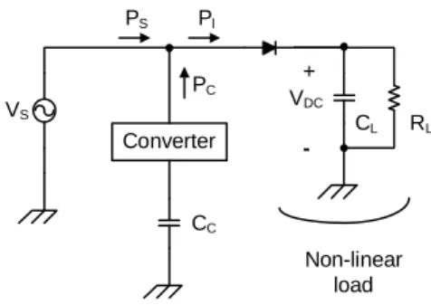
The basic circuit configuration of a utility interactive PV system is shown in Fig.1. The battery bank of a DC bus is replaced by a capacity due to less power storage in the DC bus. The system configuration is the same as APF except for the DC converter stage. DC converter stage will be disabled and the system will be transferred to APF mode during non-operation duration. The Fig. 1(a) shows the utility interaction PV system operates on generation mode, and the Fig. 1(b) shows the system operates on APF mode.
Fig. 1 The block diagram of PV power supply system
Converter VB L L L iS RL CL VDC + -Non-linear load VC + - CC il iC
Fig. 2 The block diagram of the three-phase APF system The fundamental building block of the three-phase APF system is shown in Fig.2. Under normal circumstances, the utility can be assumed as a sinusoidal voltage source.
1 and -1,0, k , Re ) ( 3) 2 ( , � � � � �t k j sm k s t V e v (1)
If a nonlinear load is applied, then the load current will consist of the fundamental component and all the higher order harmonics. It can be represented as
1 and -1,0, k , Re ) ( 3) ) 2 ( ( , 1 , � � � � � �
�
jn t k n n l n k l t I e i � � � (2) Therefore, the three-load power can be expresses as1 and 0, -1, k where , Re Re Re 2 1 cos 2 3 ) ( ) ( ) ( ) ) 3 2 ( ( ) 3 2 ( , ‡ 2 1 1 ) 3 4 2 ( 1 1 ,1 1 1 , 1 1 , , ,
‡”
‡”
‡”
‡”
1 � � � � � � � � � � � � � � � � � � n k t n j k t j n l n k sm k t j k sm l l sm k sk lk l total e e I V e I V I V t i t v t p � � � � � � � � � (3)In eq.(3), the first term is the real power supplied by the utility source, the second term is the reactive power, and the third term is the harmonic power. The last two terms are supplied by the APF. For a balanced three phase system, the second item is zero, i.e.
) ( ) ( , , t P p t ptotall � s� totalc (4) 2 3 cos 2 3 1 1 , sm m l sm s I V I V P � � � (5) 1 and 0, -1, k where , R Re ) ( 3) ) 2 ( ( 1 1 ‡ 2 ) 3 2 ( , , ‡” � � � � � � � � � jn t k n k n k t j n l sm c total t V I e ee p � � � � � (6)
As the APF provides the harmonic power Ptotal,c , the current
supplied by the utility will be
Re
)
(
3) 2 ( , � �t k j m k st
I
e
i
�
� (7) where 1 1 , cos 3 2 � l sm s m V I P I � � (8)The current is,k(t) is in phase with the utility voltage and is
pure sinusoidal. Therefore, The APF must provide the compensation current. ) ( ) ( ) ( , , , t i t i t ick � lk � sk (9)
World Academy of Science, Engineering and Technology Vol:4 2010-02-21
28
Hence, the APF needs to calculate the current is,k(t)
accurately and instantaneously as described in the following. B. Calculation of fundamental component is,k(t)
For a three-phase APF in a steady state, the energy transformations are shown in Fig. 3.
VS Converter PS Pl PC CC CL RL Non-linear load VDC +
-Fig. 3 The energy transfers in APF The power consumption of the load is
L DC L R V P 2 � (10)
This power will be provided by the utility source. Because the reactive power and harmonic power are supplied by APF, the utility only needs to supply the pure sinusoidal current and in phase with the utility voltage (i.e. pf=1.0). The power supplied by the utility is
2 3 sm m s I V P � (11) where sm L DC m V R V I 3 2 2 � � (12)
In theory, the energy-storage capacitor does not need to provide real power to the load. Therefore, at the end of one complete utility cycle, the terminal voltage of storage energy capacitor of converter will keep no change. However, owing to the switching loss and conductive loss of the power converter, the utility must provide not only the real power needed by the load (i.e. the in phase pure sinusoidal current is,k(t), but also
the additional power required by the converter to maintain the capacitor voltage at the prescribed value.
The change of energy-storage capacitor in one period will be ) -( 2 1 2 2 c ref c c C V V E � � (13) where
Vref the reference voltage of the energy-storage capacitor in
steady state
V c the voltage of the energy-storage capacitor at the end of
each utility period.
If the energy loss of the capacitor can be compensated to the set value desired at the end of the next utility cycle by the extra utility current ΔImsinωt, then in this cycle the energy
compensated by the utility will be
2 3 t) sin sin ( 3 0 T I V dt I t V T E sm m m T sm c � � � � � � �
�
� � (14)Based on the concept of energy balance, the compensation energy from the utility must equal to the energy loss of the energy-storage capacitor, i.e. ΔEs =ΔEc. Therefore, in the next
period the variation of the utility current is ) -( 3 ) -( 2 2 2 2 c ref sm c ref c m V T K V V V V C I � � � (15) where T V C K sm c 3 �
Keep in mind, this energy-loss is caused by the increment of load. If the utility makes only this variation of current, ΔIm, it
will just keep the capacitor voltage from not dropping again, and be unable to pull the capacitor voltage back to the reference level. For the capacitor voltage to return to its reference value Vref at the end of the next cycle, the utility
must provide 2ΔIm current variation in the next cycle (one ΔIm
is for the load increment and other ΔIm is for the
compensation of energy loss in the previous cycle).
Figure 4 shows the control block diagram of energy-storage capacitor voltage. The input is the terminal voltage of the capacitor. It follows an attenuation circuit (K1) to adjust this
voltage to an appropriate level (Vc/K1). Then, it is connected
to an isolation amplifier to isolate the main power circuit from the control circuit. The value of Vc2 is calculated by a square
circuit. The other input is the reference voltage (Vref/K1), it
also follows a square circuit to calculate Vref 2. The difference
between (Vc/K1)2 and the set value (Vref /K1)2 is multiplied by
K2 (K2 =K12×K) to get ΔIm. This current ΔIm adds to the
previous command current IUP1 to obtain the steady-state
utility command current of this coming period, IUP. At the
same time, one more ΔIm adds to the steady-state utility
command current IUP, to get Im (Im=IUP+ΔIm), and it will
include the component to compensate the energy loss of the previous period. At the end of this coming period, the terminal voltage of energy-storage capacitor will return to Vref.
These values are sampled at the end of each period by the sample and hold the circuit to keep the value until the end of next period. Hence, during each period, the change of energy-storage capacitor voltage does not affect the compensation characteristics of the APF. That means the capacitor can endure a much larger voltage ripple. As the results, we can reduce the capacity of this capacitor.
World Academy of Science, Engineering and Technology Vol:4 2010-02-21
29
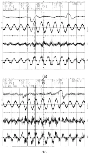
(a)
(b)
Fig. 11 The transient response test results for load current varies between IDC=0.5 p.u. and IDC=1.0 p.u.. (a) R load. (b) R-C load
Fig. 12 The sampling clock of the proposed advanced sampling technique
V. REFERENCES
[1] F. M. P. Pamplona and B. A. Souza, "Harmonic passive filter planning in radial distribution systems using genetic algorithms," pp. 126-131, 2004. [2] G. Spiazzi, E. da Silver Martins, and J. A. Pomilio, "A simple
line-frequency commutation cell improving power factor and voltage regulation of rectifiers with passive LC filter," 2001.
[3] K. Chatterjee, G. Venkataramanan, M. Cabrera, and D. Loftus, "Unity power factor single phase AC line current conditioner," 2000.
[4] H. L. Do and B. H. Kwon, "Single-stage line-coupled half-bridge ballast with unity power factor and ripple-free input current using a coupled inductor," IEEE Transactions on Industrial Electronics, vol. 50, pp. 1259-1266, 2003.
[5] K. W. Siu, Y. S. Lee, and C. K. Tse, "Analysis and experimental evaluation of single-switch fast-response switching regulators with unity power factor,"
IEEE Transactions on Industry Applications, vol. 33, pp. 1260-1266, 1997.
[6] M. Van der Berg, J. A. Ferreira, and W. Hofsajer, "A unity power factor low EMI battery charger for telecommunication applications," pp. 458-465. [7] C. Zhang, Q. Chen, Y. Zhao, D. Li, and Y. Xiong, "A Novel Active Power
Filter for High-Voltage Power Distribution Systems Application," IEEE
Transactions on Power Delivery, vol. 22, pp. 911-918, 2007.
[8] G. W. Chang and C. M. Yeh, "Optimization-based strategy for shunt active power filter control under non-ideal supply voltages," IEE
Proceedings-Electric Power Applications, vol. 152, pp. 182-190, 2005.
[9] W. U. Jin-Chang and H. L. Jou, "Novel Circuit Topology for Three-Phase Active Power Filter," IEEE Transactions on Power Delivery, vol. 22, pp. 444-449, 2007.
[10] H. L. Jou, J. C. Wu, Y. J. Chang, and Y. T. Feng, "A novel active power filter for harmonic suppression," IEEE Transactions on Power Delivery, vol. 20, pp. 1507-1513, 2005.
[11] H. H. Kuo, S. N. Yeh, and J. C. Hwang, "Novel analytical model for design and implementation of three-phase active power filter controller," IEE
Proceedings-Electric Power Applications, vol. 148, pp. 369-383, 2001.
[12] B. Singh, B. N. Singh, A. Chandra, K. Al-Haddad, A. Pandey, and D. P. Kothari, "A review of three-phase improved power quality AC-DC converters," IEEE Transactions on Industrial Electronics, vol. 51, pp. 641-660, 2004.
[13] K. P. Sozanski, "Shunt active power filter with improved dynamic performance," pp. 1995-1999, 2008.
[14] X. Wei, K. Dai, X. Fang, P. Geng, F. Luo, and Y. Kang, "Parallel Control of Three-Phase Three-Wire Shunt Active Power Filters," 2006.
[15] Y. C. Kuo, T. J. Liang, and J. F. Chen, "A high-efficiency single-phase three-wire photovoltaic energy conversion system," IEEE Transactions on
Industrial Electronics, vol. 50, pp. 116-122, 2003.
[16] Z. Chunyu, L. Yabin, and P. Yonglong, "A direct phase control scheme for unity power factor three-phase buck type rectifier based on SVPWM," 2006. [17] H. Do an and R. Akkaya, "A Simple Control Scheme for Single-Phase Shunt Active Power Filter with Fuzzy Logic Based DC Bus Voltage Controller," Proceedings of the International MultiConference of Engineers
and Computer Scientists, vol. 2, 2009.
[18] C. M. Liaw, T. H. Chen, T. C. Wang, G. J. Cho, C. M. Lee, and C. T. Wang, "Design and implementation of a single phase current-forced switching mode bilateral converter," IEE Proceedings B [see also IEE
Proceedings-Electric Power Applications] Electric Power Applications, vol.
138, pp. 129-136, 1991.
[19] L. Bowtell and A. Ahfock, "Comparison between unipolar and bipolar single phase grid connected inverters for PV applications," pp. 1-5, 2007. [20] T.-F. Lee, Y.-C. Hsiao, H.-Y. Wu, T.-L. Huang, F.-M. Fang, and M.-Y.
Cho, "Optimization of reactive power compensation and voltage regulation using artificial immune algorithm for radial transmission networks,"
Engineering Intelligent Systems, vol. 15, pp. 107-113, 2007.
World Academy of Science, Engineering and Technology Vol:4 2010-02-21
34