Cross Layer Design of Handoffs in IEEE 802.16e Network
6
0
0
全文
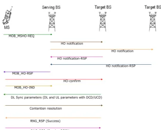
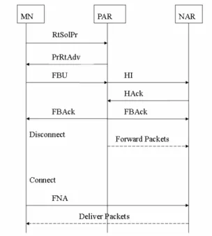
(2) This paper is organized as follows. In the following section, the handoff scenarios and related message sequence charts of 802.16e and fast mobile IPv6 are briefly reviewed. The proposed procedure of cross layer handoff is stated in section III. In section IV, we examine the performance of the proposed scheme through simulations and the results of our scheme are compared with the scheme proposed in [4] in this section. And, finally, conclusions of this paper and future researches are provided.. the target BS to allocate additional downlink sub-carrier and bandwidth for the MS. After obtaining the ranging results, the decision of which BS the MS is going to handoff can be made by either the MS or the serving BS. The basic procedure of handoff is illustrated in Figure 1. It shows that the serving BS sends “handoff (HO) notification” to two target BSs after receiving the handoff request initiated by MS. And the serving BS selects a target BS and sends the “HO response” to MS after receiving the “HO notification response” messages sent by target BSs.. 2: Overview of 802.16e Mobility and Fast Mobile IPv6 Performance of handoff is the most important issue discussed in mobile environment. As traditional communication technology is constructed in layered approach, to handoff an existing connection or service stream is a complex procedure. The main functions of layer 2 layer 3 are to deal with hop-by hop link and end-to-end connection issues, respectively. Hence the objectives of handoff at different layers are different. IP service is the most popular layer-3 protocol, however, it may run over various kinds of layer-2 protocols. In this paper we consider the mobility issue of IP over 802.16e environment. And the basic mobility scenarios of 802.16e and fast mobile IPv6 are briefly described in the following.. MOB_MSHO-REQ HO notification HO notification HO notification-RSP HO notification-RSP MOB_HO-RSP HO-confirm MOB_HO-IND DL Sync parameters (DL and UL parameters with DCD/UCD) Contention resolution. RNG_RSP (Success) RNG_REQ (Serving BSID). Figure 1. 2.1 802.16e Mobility. The message sequence chart of handoff in 802.16e. The mobility supported in 802.16e can be divided into the following steps: -. Cell reselection. 2.2 Fast Mobile IPv6. -. Handoff decision and initiation. -. Synchronization to target BS. -. Handoff ranging. -. Termination of MS context. The basic idea of fast mobile IPv6 is to allow some procedure of IP mobility to be processed in an earlier stage. Mainly, the mobility procedure of IP layer can be divided into two steps: The first one is to get the care of address (CoA) and the second one is to register the obtained CoA at home agent and correspondent node (CN) (if route optimization is required). The fast mobile IPv6 is to assist the mobile node to get its CoA before the initiation of handoff. There are two possible scenarios, named as predictive mode and reactive mode, as shown in Figure 2 and 3, for fast mobile IPv6 depending on whether the MS can connect to its previous access router (PAR) or not when sending the fast binding update (FBU) message. The reactive mode (i.e. the FBU message can not be reached PAR and shall be tunneled to the next access router (NAR)) happened when MS is moving fast. It is noted that the disconnection interval existed when the mobile node disconnects the PAR and is waiting for NAP as shown in Figure 2 and 3.. In order to speedup the handoff delay, in 802.16e, the mobile station is allowed to issue scan request for target BSs. Three kinds of associations are defined to assist the scan procedure of MS. Level 0 association is the most straightforward scheme where no coordination process between serving BS and target BS is performed. After get the permission for scan by the serving BS, the mobile station shall contend with the MS of the target BS, which it is going to scan, for sending ranging request message to the target BS. Level 1 and 2 association were proposed with the coordination of the serving BS. That is the serving BS will negotiate with the target BSs in advance so that the MS can avoid the contention procedure. And the main difference between level 1 and 2 is that the ranging results replied by the target BSs (through BS-to-BS interface) will be collected by the serving BS in level 2 association. This arrangement has the advantage that there is no need for. - 704 -.
(3) Figure 2. In order to improve the handoff delay of IP over 802.16e environment, we propose the cross layer handoff scheme (CLHS) to integrate the correlated messages of 802.16e and fast MIPv6. We analyze the message flow sequences and the message formats of 802.16e and fast MIPv6 firstly. Our purpose is to examine the correlation between these two procedures and to minimize the control flow. We found that some L3 handoff information can be integrated with the MOB_HO_IND message and RNG_REQ message of 802.16e because they have the same semantic characteristics during performing the handoff. The main reason is that when the MS decides to handoff, its target BS shall have already been determined when the MS sends the MOB_HO_IND. And the FBU message of fast MIPv6 is to inform its AR for the initiation of layer 3 handoff. It is reasonable to send the FBU together with MOB_HO_IND. Therefore, we modify the original MOB_HO_IND message to include FBU as a new message “FBU-MOB_HO-IND” and is specified Table 1. Basically, we adopt one bit from the reserved 6 bits of original layer 2 MOB_HO_IND message to indicate the enable and disable of FBU capability in layer 3. When the serving BS receives the FBU-MOB_HO-IND message with FBU bit set, it, in stead of MS, will send FBU message to PAR. Thus, this arrangement can guarantee the information of FBU and MOB_HO_IND can be sent together. Either these two information can be sent successfully or falsely. If the handoff of layer 2 and 3 can be coincident, the overhead to deal with the inconsistence will be reduced. Based on the same concept, the procedure of reactive mode shall also be modified. We found that there are 8 reserved bits in the RNG_REQ message of 802.16e and it can be applied to inform the FNA information used in fast MIPv6 when it is in reactive mode. Hence we modified the RNG_REQ message to become the FNA_ RNG_REQ message as specified in Table 2.. The predictive mode fast MIPv6. Table 1. Figure 3. FBU_MOB_HO-IND message format. Syntax Management Message Type FBU. Size 8 bits. Notes Value = 59. 1 bit. Reserved. 5 bits. Mode. 2 bits. 0b00: FBU disable 0b01: FBU enable Reserved; shall be set to zero 0b00: HO 0b01: MDHO/FBSS: Anchor BS update 0b10: MDHO/FBSS: Diversity Set update 0b11: Reserved The other detail is abridged. The reactive mode fast MIPv6. In order to achieve the complete handoff procedure, a direct way is to overlay the handoff procedure of layer 2 over layer 3 [4]. However, it can be found that this scheme requires procedure of layer 3 to be performed after that of layer 2, the duration of disconnection time increases.. 3: Cross Layer Design for L2 and L3 Handoff. - 705 -. …. ….
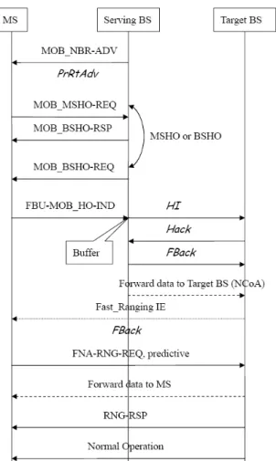
(4) Table 2. FNA_ RNG_REQ message format. Syntax Management Message Type Predictive FNA bit Reactive FNA bit Reserved TLV Encoded Information. Size. Notes. 8 bits. Value = 4. 1 bit 1 bit 6 bits variable. Predictive FNA Reactive FNA Shall be set to zero TLV specific. In addition to modifying these two messages, we make a little modification and combining on the message of neighbor advertisement in layer 3 and the message of ranging request in layer 2. The “MOB_NBR_ADV” message is periodically sent by the BS and its function is similar to the “PrRtAdv” message in fast MIPv6. So, these two periodical advertisement messages can be combined together. And the original fast binding acknowledgement message, FBack, is applied to inform the status of the configuration of CoA. We combine the “FBack” of fast MIPv6 and the “Fast Ranging IE” to be sent by the target BS such that the MS can be informed that the next CoA is valid. The proposed scheme is suitable to be applied either the BS and AR are separated or integrated together. The message sequence chart of the proposed CLHS with predictive mode for the cases of separated BS/AR and integrated BS/AR are shown in Figure 4 and 5, respectively. It shall also be noted that the proposed scheme can satisfy both of the reactive mode and the predictive mode because both conditions are considered in our scheme.. Figure 5 Predictive CLHS with integrated BS/AR. 4: Performance Simulations The performance of the proposed scheme is examined through exhaustive simulations. A network topology with 7 base stations, as shown in Figure 6, is applied for simulation. In our simulation model, each base station has 4 circles, which denote different channel conditions. From the inner circle to the most outside circle, the channel condition is assumed to be getting worse. We assume that each MS will always select the BS with the best channel condition. For example, if a MS is moving as shown in Figure 6, the MS will decide to handoff from BS 3 to BS 7 because the MS will be in the second circle of BS 7 after movement and the channel condition with BS 7 will be better than that of BS 3, which is located at the forth circle. The mobility model of each MS is assumed to be with random way point [6]. The speed of each MS is uniformly distributed between 0~120 K Meters/hour. If the speed is 0, it means that the MS stops within that interval (halt duration). And the halt time is exponentially distributed with mean 15 seconds while within the ranges of 3 seconds and 30 seconds. The transmission delay between base stations is 5 ms. It is assumed that the moving area of mobile station is confined by the outer rectangular and only the handoff Figure 4 Predictive CLHS with separated BS/AR. - 706 -.
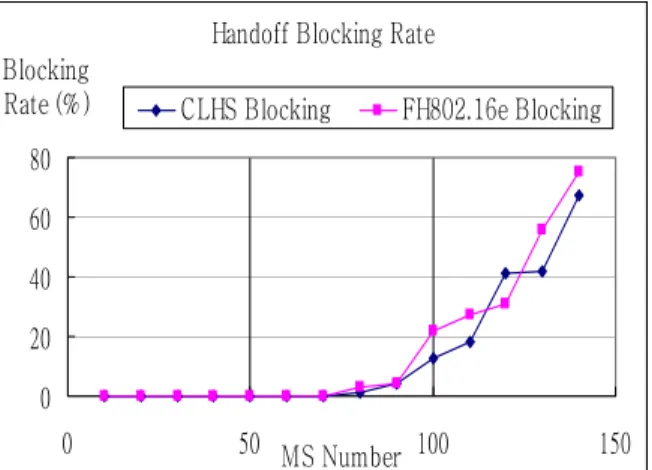
(5) behaviors occurred inside the inner rectangular are taken into consideration for simulation results.. Handoff Delay CLHS Predictive FH802.16e Predictive. Handoff Delay (ms). CLHS Reactive FH802.16e Reactive. 300 250 200 150 100 50. MS. 0 0. 20. 40. 60. 80. 100. 120. 140. 160. MS Number. Figure 7 Handoff delay v.s. number of MS Figure 6 Simulation topology The simulation results are divided into two parts. The first part is mainly related to the handoff latency and the second part is related to the blocking rates of handoff for the proposed scheme and the scheme proposed in [4]. If handoff is blocked, the mobile stations need follow the normal procedure to enter network of target BS. Figure 7 compares the handoff delay of the proposed CLHS and the fast handoff for 802.16e (FH802.16e) scheme proposed in [4]. It is noted that the delay time is mainly dependent to the number of messages to be processed in our simulation and the message shall be processed within the duration of an 802.16e frame and will be response to its peer in the following frame. We did not consider the processing overhead of BS in our simulations. Hence it is found that the delay time is insensitive to the number of mobile stations. However, the handoff latency of our scheme is less than that of FH802.16e. The reason is that our scheme needs less number of messages than that of FH802.16e when performing handoff. Figure 8 shows the handoff delay time versus the frame duration. Frame duration means the time between the beginning of a MAC frame and the end of that frame . It indicates that the delay time increases as the frame duration increases. The main reason is that the resource utilization of current frame is scheduled in advance (prior to current frame) and BS can only reply the received message at the next frame. And the response time is lengthened as the frame duration increases. Although the delay time of the proposed scheme also increases with respect to the frame duration, our scheme is still superior to that of FH802.16e.. Frame Duration and Handoff Delay Handoff Delay (ms). CLHS. FH802.16e. 200 150 100 50 0 0. 5. 10. 15. 20. 25. Frame Duration (ms) Figure 8 Handoff delay v.s. frame duration The blocking and success rates of handoff versus number of number of mobile stations for CLHS and FH802.16e are depicted in Figure 9 and 10, the sum of the two value should be 100% , respectively. Here we assume the frame duration is 20ms, and the MS capacity of each BS is 20. If the MS can not receive the handoff response, the number of retries is 3 and the retry interval is 200ms. The reactive mode for both schemes has less success handoff ratio than that of predictive mode. And it also shows that there is no significant difference between these two schemes. And The main reason is that the difference between these two schemes is the number of message, which mainly affects the performance of handoff delay not the network capacity. We believe the capacity of BS is the main criteria that affect the blocking rate.. - 707 -.
(6) the frame duration so that the optimal network throughput and handoff performance can be achieved.. Handoff Blocking Rate Blocking Rate (% ). CLHS Blocking. FH802.16e Blocking. Acknowledgement. 80. This research was supported in part by the grants from National Science Council (NSC94-2213-E-008-036, and 95-2221-E-008-030).. 60 40 20. References [1]. 0 0. 50 MS Number 100. 150. [2]. Figure 9 Handoff blocking rates v.s. number of MS [3]. Handoff Success Rate CLHS Predictive FH802.16e Predictive. Success Rate (%). [4]. CLHS Reactive FH802.16e Reactive. 150. [5]. 100 50. [6]. 0 0. 50. MS Number. 100. 150. [7]. Figure 10 Handoff success rates v.s. number of MS. 5: Conclusions In this paper, we propose an integrated layer 2 and layer 3 handoff scheme based on the concept of cross layer. The cross layer design is performed by the consideration of correlation between layer 2 and 3. Our main contribution in this paper is to combine the L2 and L3 handoff message smoothly so that the total number of control message can be reduced. And after the integration, as some handoff events of layer 2 and layer 3, such as periodical advertisement (PrRtAdv and MOB_NBR_ADV), handoff initiation (FBU and MOB_HO_IND, FNA and RNG_REG), are sent together such that the handoff of layer 2 and layer 3 can be more synchronized. In addition, we compare our scheme with previous scheme through exhaustive simulations and found that the hand off delay of our scheme is superior to that of the other scheme. In this paper, we do not consider the selection mechanism of an appropriate BS and the avoidance of connection oscillation between base stations during handoff. These issue is important especially when the connection with quality of service (QoS) is considered. Future research may extend the concept of cross layer to cover the complete handoff procedure and to dynamically adjust. - 708 -. IEEE Computer Society, IEEE Microwave Theory and Techniques Society, “ IEEE Std 802.16-2004", IEEE Standard, 1 October 2004. IEEE Computer Society, IEEE Microwave Theory and Techniques Society, “IEEE Std 802.16e-2005 and IEEE Std 802.16-2004/Cor12005”, IEEE Standard, 28 February 2006. Rajeev Koodli,“Fast Handovers for Mobile IPv6,” IETF RFC-4068, July 2005. Heejin Jang, Junghoon Jee, Youn-Hee Han, Soohong Daniel Park, Jaesun Cha, “Mobile IPv6 Fast Handoffs over IEEE 802.16e Networks < draft-jang-mipshop-fh80216e-02.txt>”, IETF Internet-Draft, 27 February 2006. Sik Choit, Gyung-Ho Hwangt, Taesoo Kwont, Ae-Ri Limt, Dong-Ho Chot, “ Fast Handoff Scheme for Real-Time Downlink Services in IEEE 802.16e BWA System " , Vehicular Technology Conference, May 2005. Chr.Bettstetter, H.Hartenstein, and X.P´erez-Costa, “Stochastic Properties of the Random Waypoint Mobility Model,” ACM Mobicom Workshop MSWIM, 2002. D. Johnson, C. Perkins, “Mobility Support in IPv6 ", IETF RFC-3775, June 2004..
(7)
數據

+2
相關文件
Included in them are 5 056 real estate units amounting to 2.43 billion Patacas, representing variations of -19.8% and -19.7% respectively in number and value over the fourth quarter
6 《中論·觀因緣品》,《佛藏要籍選刊》第 9 冊,上海古籍出版社 1994 年版,第 1
The first row shows the eyespot with white inner ring, black middle ring, and yellow outer ring in Bicyclus anynana.. The second row provides the eyespot with black inner ring
A floating point number in double precision IEEE standard format uses two words (64 bits) to store the number as shown in the following figure.. 1 sign
You are given the wavelength and total energy of a light pulse and asked to find the number of photons it
A floating point number in double precision IEEE standard format uses two words (64 bits) to store the number as shown in the following figure.. 1 sign
Wang, Solving pseudomonotone variational inequalities and pseudocon- vex optimization problems using the projection neural network, IEEE Transactions on Neural Networks 17
Consistent with the negative price of systematic volatility risk found by the option pricing studies, we see lower average raw returns, CAPM alphas, and FF-3 alphas with higher
