play, a flat panel can sense the images reflected off a bare finger. The three-axis (x, y, z) information of the fingertip can be deter-mined by analyzing these reflected images. The proposed 3-D vir-tual-touch system successfully functions with a 4-in mobile display. Index Terms—Three-dimensional (3D) virtual touch, embedded optical sensors.
I. INTRODUCTION
T
OUCH systems are interface between users and machines. Most current mobile displays are limited to a 2-axis (x and y) positioning for objects [1]. These axes are insufficient for 3D displays [2]–[5] or other 3D interactive applications. Many methods and devices, such as the WorldViz PPT (precision po-sition tracking) [6], the Wii, etc., have been used to achieve 3D interactivity. However, none of these technologies are ap-plicable to mobile display applications. A 3D mobile display with 3D virtual touch functionality can provide a more intuitive and friendly interface, as shown in Fig. 1.Current 3D interactive systems primarily fall into machine-based and camera-machine-based groups. Machine-machine-based systems [7] require wearing additional devices to detect motion, and can provide feedback vibrations to the users. However, these sys-tems are considered inconvenient because they require addi-tional heavy devices to be worn.
For camera-based systems [8]–[12], 3-axis (x, y, z) positions can be calculated using various methods. For instance, the pop-ular Kinect [13] can detect relative 3-axis (x, y, z) positions using two infrared (IR) cameras with a corresponding IR light source. However, this camera-based system requires high reso-lution images to calculate the 3-axis (x, y, z) positions, and the resolution is proportional to the size of camera sensor; therefore, Manuscript received April 01, 2013; revised July 31, 2013; accepted August 01, 2013. Date of publication August 07, 2013; date of current version De-cember 27, 2013. This work was supported by the National Science Council of Taiwan through Academic Projects NSC 101-2221-E-009-120-MY3.
G.-Z. Wang and T.-S. Chang are with the Department of Electronic Engi-neering, National Chiao Tung University, Hsinchu 300, Taiwan.
Y.-P. Huang is with the Photonics Department, Display Institute, Hsinchu 300, Taiwan.
T.-H. Chen is with the School of Electrical and Computer Engineering, Cor-nell University, Ithaca, NY 14850 USA.
Color versions of one or more of the figures are available online at http:// ieeexplore.ieee.org.
Digital Object Identifier 10.1109/JDT.2013.2277567
Fig. 1. Concept of playing a virtual 3D STACKO game on a 3D mobile display using air-touch technology.
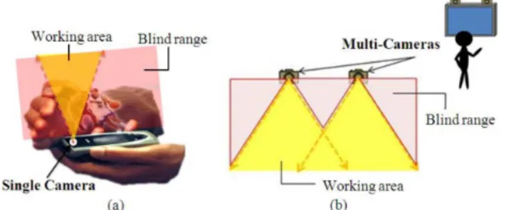
Fig. 2. The limited field of view for both (a) single-cameras and (b) multi-cameras causes a blind range within the continuous interaction space.
the form factor impedes such systems from being integrated into a portable device. The Leap 3D motion control system was re-cently unveiled by a San Francisco startup called “Leap Motion” and can provide a 3D hands-free motion controller. However, the Leap Motion technology still requires an additional device and is thus not suited to mobile devices.
Camera-based systems are usually limited by their field of view (Fig. 2) and form factor, which prevents them from de-tecting objects in close proximity to the display and being inte-grated into portable devices such as smart phones and tablet.
Another example is the BiDi screen that was proposed by M. Hirsch in 2009 [14]. The BiDi screen uses a sensor layer a small distance from the normal LCD display. When this sensor layer views an object through the optical mask, information about the distance the object is in front of the screen can be captured and decoded. This technology is generally known as depth from focus [15]. Because a BiDi screen uses an optical tiled-MURA mask to capture information about the object, it relies on the en-vironmental brightness. Without sufficient lighting, the device cannot capture a clear image. Furthermore, the mask decreases the detected brightness, which increases the required ambient conditions.
For application in real portable devices, an embedded optical sensor based approach [16]–[18] was proposed that can be in-tegrated into the display pixels to provide light and maintain a 1551-319X © 2013 IEEE
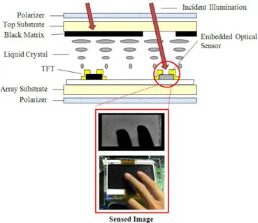
Fig. 3. Schematic structure of an optical sensor embedded onto a TFT substrate and the sensed image.
thin form. As shown in Fig. 3, the embedded optical sensors are not blocked by the black matrix, thus a photo current will occur when the sensor receives light. The embedded optical sensor was first proposed for 2D touch applications [19] and has been recently extended for 3D interactions [20]. However, the device still required a light pen for previous applications [21], [22]. To achieve a bare finger 3D air-touch device, we proposed an embedded optical sensor system with angular scanning illumi-nators added to the display edges, as shown in Fig. 4. The pro-posed system allows for near-distance 3D air-touch function-ality above the entire surface of the display. Additionally, it can be very compact and independent of ambient conditions. There-fore, floating 3D images can be touched and interacted with.
II. CONSTRUCTION ANDMETHOD
The proposed bare finger 3D virtual touch system is construc-tion from a tradiconstruc-tional display, embedded optical sensors, in-frared (IR) backlight, and angular scanning illuminators. To cal-culate the 2-axis (x and y) positions of a fingertip, the IR back-light pass through the panel and are reflected by the fingertip as shown in Fig. 4(a). To calculate the depth (z) of the fingertip, the IR angular scanning devices are placed on opposite sides of the panel as shown in Fig. 4(b).
Unlike previous image capturing techniques, which are strongly dependent on ambient illumination, the proposed system uses embedded IR sensors and light sources. The de-background image processing of each detected frame allows the device to operate under various ambient conditions.
The flow chart of proposed algorithm is shown in Fig. 5. At first, the raw data is retrieved from embedded optical sen-sors. For reducing noises from environment and system, noise suppression which include de-noise and de-background will be adopted.
Second, intensity of captured image from IR backlight needs to be accumulated. When the accumulated value is larger than touch threshold value, which is determined by the calibration
Fig. 4. Cross section of the bared finger 3D virtual touch system in (a) IR back-light illumination mode (for x and y determination) and (b) IR angular scanning mode (for z determination).
Fig. 5. Flow chart of the bare finger 3D air-touch algorithm.
data, the object will be sensed as touching on the panel. Then the “full search method” can be used to determine the 2-axis (x and y) position of a touch point. Finally, if less than the threshold, the object is hover of the screen, thus the proposed “region based algorithm” will be induced to calculate the depth (z) informa-tion. The details of “region based algorithm” will be described in the following.
Fig. 7. Concept for the region based algorithms in the different working regions.
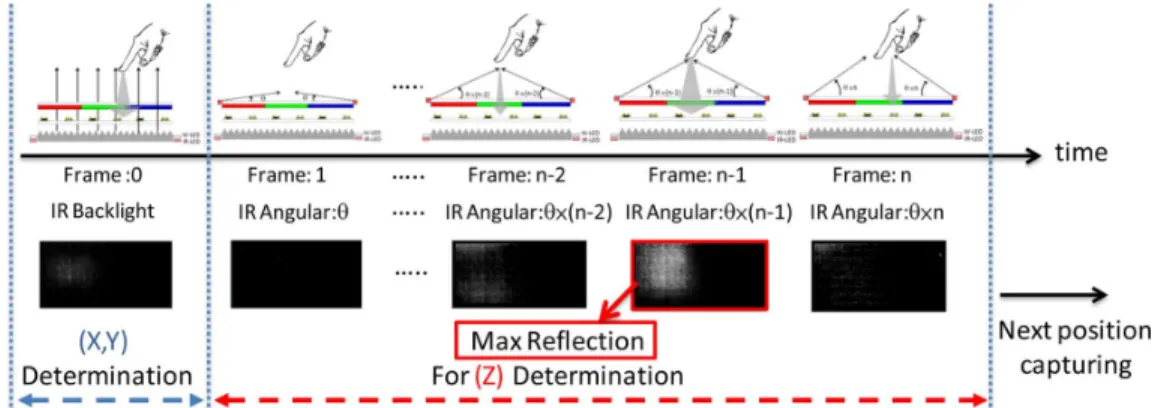
Next, we present the timing diagram (Fig. 6) for the pro-posed bare finger 3D virtual touch system to clearly illustrate the working process. Initially, the IR backlight and IR angular scanning illuminators will need to be synchronized with the em-bedded optical sensors. In the first sensing frame (Frame 0), the IR backlight passes through the panel twice and the optical sen-sors capture any reflected light to determine the 2D position (x and y) of the fingertip. Next, the IR angular scanning illumina-tors on the both sides of the panel will sequentially emit light at different tilt angles. These sensing frames (Frame 1 to Frame n) correlate to a tilt angle from to . Finally, analyzing the accumulated intensity of each frame provides the scanning angle with the maximum reflectance and thus the location of the fingertip. From the 2-axis (x and y) position and scanning angle , the depth (z) of the fingertip can be calculated. Finally, the 3D virtual touch coordinates (x, y, z) can be obtained. In the
proposed system, the algorithm for calculating the 3-axis (x, y, z) position of the fingertip is less complex than for image pro-cessing.
To calculate the 2-axis (x and y) position of a fingertip, the full search method is used to analyze the reflected IR backlight image. The full search method [9] uses a filter covered by the image to total the intensity and determine the position with the highest accumulated intensity, which is the 2-axis (x and y) po-sition of the object.
In the following steps, the images from the IR angular scanning can be processed using a region-based algorithm to obtain the depth (z) of the fingertip as shown in Fig. 6. This region-based algorithm exploits the proposed design concept to divide the hover region into three working ranges, 1 (overlapping-central), 2 (overlapping-wings), and 3 (non-over-lapping) as illustrated in Fig. 7. In the working range, 1
Fig. 8. Measurement results for the reflected intensity of a fingertip at different depths.
(overlapping-central), the fingertip is centered over the display and reflects the two side illuminators at the same tilt angle . Therefore, the intensity of the tilt angle curve only has a single peak for the scanning angle with the maximum reflectance from the fingertip. When the fingertip is in working range 2 (overlapping-wings), it reflects the two side illuminators at different tilt angles ( and ). Therefore, the intensity vs. tilt angle curve has two peaks. With working range 3 (non-over-lapping), the curve has only a single peak because the fingertip is beyond the scan angle of the closer illuminator. Finally, with both the scanning angle and 2-axis (x and y) position of the fingertip, the depth (z) information can be calculated using a
simple trigonometric function .
The proposed approach is suitable for touching and inter-acting with floated 3D images from a mobile display. Further-more, the proposed approach has the advantages of providing near-field support for full screen detection, simple algorithms for real-time calculations, and built-in illuminators for indepen-dence from ambient conditions.
III. RESULTS
A prototype 3D air-touch system was built using a 4-inch LCD equipped with IR sensors integrated onto the TFT sub-strate. The sensor resolution was 68 120, which is one fourth the image resolution of the display. For implementing the pro-posed concept, the high collimated light and scanning mirror was used to simulate the sequential lighting source. Further-more, the sequential lighting sources were synchronized with optical sensors.
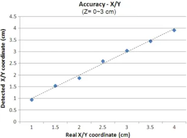
To verify the accuracy of the 3-axis (x, y, z) positioning of a fingertip above the 4-inch mobile display, a test of x/y and depth (z) coordinates ranging from 1–4 cm and 0–3 cm, respectively. The depth range was limited by the low sensitivity of the current embedded optical sensors. As shown in Fig. 8, the reflected IR intensity decreased to almost zero when approaching 4 cm in height. The experiment results shown in Figs. 9 and 10 indicate the detected coordinates of X/Y and the depth (z) matched the real value. The average error was less than 0.2 cm (x/y) and 0.3 cm (z). Furthermore, the maximum error in 3-axis (x, y, z) direction will, of course, increase with increasing depth (z) as
Fig. 9. Accuracy of the x/y coordinates at different depths (z) for the object
( cm).
Fig. 10. Accuracy of the depth (z) of the object at different x/y coordinates.
Fig. 11. Maximum error for the x/y and z coordinates at different depths (z) for the object ( cm).
shown in Fig. 11. This trend was because of the scattering effect of the fingertip and the increased scanning gap. However, in our experiment, the maximum error of the depth (z) was 0.45 cm, which can satisfy the Win 7 standard (0.5 cm increment) for 2D touch.
Fig. 12. Comparison of 3D multi-touch in the IR backlight illuminating mode (for the x, y determination) under (a) normal and (b) failing circumstances.
Fig. 13. Comparison of a 3D multi-touch system in the IR angular scanning mode (for the z determination) under (a) normal and (b) failing circumstances.
IV. DISCUSSIONS
To summarize, the approach described above focuses on a 3D virtual single-touch interface. However, including multi-touch functionality could enable more applications for the 3D user in-terface. Such an interface could be workable with the proposed system; however most multi-touch applications will fail due to the occlusion effect. Fig. 12 shows how the xy-axis of a fingertip in an occluded area cannot be distinguished. Furthermore, if the occlusion area is in the overlapping-wings, the blocked fingertip cannot reflect IR light as shown in Fig. 13, which causes a failure in the multi-touch detection of the depth (z). The interpolation and motion vector methods may be used to overcome the above-mentioned occlusion issues and achieve 3D virtual multi-touch functionality.
V. CONCLUSION
In conclusion, we have presented a camera-free 3D interac-tive system for providing bare finger air-touch functionality to mobile displays. By embedding optical sensors into the pixels of a display and adding angular scanning illuminators to its edge, a flat panel can sense images reflected from fingertips under most ambient conditions. The sensed images are then used to calculate the 3-axis (x, y, z) position of the fingertip without re-quiring complex image processing. Finally, the proposed system has been demonstrated using a 4-inch mobile 3D display with a working depth range (z) of up to 3 cm; this range can be further
[1] A. D. Wilson, “Playanywhere: A compact interactive tabletop projec-tion-vision system,” in Proc. 18th Annu. ACM Symp. User Interface
Software Technol., 2005, pp. 83–92.
[2] J. Y. Son, B. Javidi, S. Yano, and K. H. Choi, “Recent developments in 3-D imaging technologies,” J. Display Technol., vol. 6, no. 10, pp. 304–403, Oct. 2010.
[3] Y. Takaki, “Multi-view 3D display employing a flat-panel display with slanted pixel arrangement,” J. Soc. Inf. Display, vol. 18, no. 7, pp. 476–482, 2010.
[4] Y. P. Huang, C. W. Chen, and Y. C. Huang, “Superzone Fresnel liquid crystal lens for temporal scanning auto-stereoscopic display,” J.
Dis-play Technol., vol. 8, no. 11, pp. 650–655, Nov. 2012.
[5] Y. P. Huang, L. Y. Liao, and C. W. Chen, “2D/3D switchable au-tostereoscopic display with multi-electrically driven liquid crystal (MeD-LC) lenses,” J. Soc. Inf. Display, vol. 18, no. 9, pp. 642–646, 2010.
[6] G. Welch and E. Foxlin, “Motion tracking: No silver bullet, but a re-spectable arsenal,” Comput. Graph. Appl., vol. 22, no. 6, pp. 24–38, 2002.
[7] S. Feiner, B. Maclntyre, T. Hollerer, and A. Webster, “A touring machine: Prototyping 3D mobile augmented reality systems for ex-ploring the urban environment,” in Proc. 1st IEEE Int. Symp. Wearable
Comput., 1997, pp. 74–81.
[8] A. D. Wilson, “TouchLight: An imaging touch screen and display for gesture-based interaction,” in Proc. 6th Int. Conf. Multimodal
Inter-faces, 2004, pp. 69–76.
[9] T. Schlömer, B. Poppinga, N. Henze, and S. Bol, “Gesture recognition with a Wii controller,” in Proc. 2nd Int. Conf. Tangible and Embedded
Interaction, 2008, pp. 11–14.
[10] T. Schou and H. J. Gardner, “A Wii remote, a game engine, five sensor bars and a virtual reality theatre,” in Proc. 19th Australasian Conf.
Comput.-Human Interaction: Entertaining User Interfaces, 2007, pp.
231–234.
[11] D. Valkov, F. Steinicke, G. Bruder, and K. Hinrichs, “2D touching of 3D stereoscopic objects,” in Proc. SIGCHI Conf. Human Factors
Com-puting Syst., 2011, pp. 1353–1362.
[12] G. D. Morrison, “A camera-based input device for large interactive displays,” IEEE Comput. Graph. Appl., vol. 25, no. 4, pp. 52–57, Jul.-Aug. 2005.
[13] Lange, B. Flynn, and A. A. Rizzo, “Initial usability assessment of off-the-shelf video game consoles for clinical game-based motor re-habilitation,” Phys. Ther. Rev., vol. 14, pp. 355–363, 2009.
[14] M. Hirsch, D. Lanman, H. Holtzman, and R. Raskar, “BiDi screen: A thin, depth-sensing LCD for 3D interaction using light fields,” in Proc.
ACM SIGGRAPH Asia, 2009, pp. 62–65.
[15] A. Levin, R. Fergus, F. Durand, and W. T. Freeman, “Image and depth from a conventional camera with a coded aperture,” ACM Trans.
Graphics, vol. 26, no. 3, 2007.
[16] A. Brown, D. Montgomery, J. L. Castagner, H. Kato, and Y. Kan-bayashi, “31.3: A system LCD with integrated 3-dimensional input de-vice,” in SID Symp. Dig. Tech. Papers, 2010, vol. 41, pp. 453–456. [17] T. Nakamura, H. Hayashi, M. Yoshida, N. Tada, M. Ishikawa, T. Motai,
H. Nakamura, and T. Nishibe, “Incorporation of input function into displays using LTPS TFT technology,” J. Soc. Inf. Display, vol. 14, pp. 363–369, 2006.
[18] A. Abileah, W. Boer, T. Larsson, T. Baker, S. Robinson, R. Siegel, N. Fickenscher, B. Leback, T. Griffin, and P. Green, “59.3: Integrated op-tical touch panel in a 14.1 AMLCD,” in SID Symp. Dig. Tech. Papers, 2004, vol. 35, pp. 1544–1547.
Guo-Zhen Wang received an M.S. degree in display
institute at the National Chiao Tung University (NCTU), Hsinchu, Taiwan, in 2008 and is currently working toward a Ph.D. at the Department of Elec-tronics Engineering, National Chiao Tung University (NCTU). His current research is to develop 3D in-teraction systems and focusses on image processing and computer architecture technologies.
Yi-Pai Huang received his B.S. degree from
Na-tional Cheng Kung University in 1999 and earned a Ph.D. in electro-optical engineering from the National Chiao Tung University in 2004. He is currently a full-time associate professor in the de-partment of photonics & display institute, National Chiao Tung University, Taiwan. He has also been a visiting associate professor at Cornell University from 2011 to 2012. Additionally, he is the chairman of the SID Taipei Chapter, and Chair of the APV program sub-committee, SID. His expertise includes 3D displays and interactive technologies, display optics and color science, and micro-optics. In these fields, he has so far published over 40 Journal and 100 International conference papers and has been granted more than 50 patents. In addition, he has thrice received the SID’s distinguished paper award (2001, 2004, 2009).
part of an organizing committee or technical program committee member. He is current an Editorial Board Member of the IEEE Transactions of Circuits and Systems for Video Technology.
Tian-Sheuan Chen received his B.S. from the
Na-tional Taiwan University and his M.S. and Ph.D. from Caltech, all in electrical engineering. After working for Bell Labs for several years, he joined the ECE fac-ulty at Carnegie Mellon University in 1997. There, in addition to his research and teaching responsibil-ities, he served as the associate department head of ECE and the co-director of the Industrial Technology Research Institute (ITRI) Laboratory, a collaborative research program with ITRI in Taiwan. In January 2009, Chen was chosen to become the director of the School of Electrical and Computer Engineering at Cornell University after an extensive national search.