國立交通大學
材料科學與工程學系
博士論文
含氫鍵之香蕉型液晶超分子之研究
Study of Hydrogen-Bonded Banana-Shaped
Supramolucular Liquid Crystals
研究生:王怜詠 (Ling-Yung Wang)
指導教授:林宏洲 (Hong-Cheu Lin) 博士
誌謝
感謝國家科學委員會、中華映管在這四年中對實驗室經費上的幫助,也感謝 同步輻射提供光束線 17A1 光源儀器,讓作者得以完成此論文研究。 大家常說,要撐完整個博士班的過程非常煎熬,因為耗時甚鉅,不過這段日 子終究是結束了,想起以往經常於研究中絞盡腦汁的樣子,頓時倍感有趣。在研 究中燃燒生命的同時,也常想起家人不厭其煩的叮嚀,要我注意身體,做事要慢 慢來,有空要回家看長輩。雖然這些轟炸式提醒我都沒做好半樣,不過回首往事, 這些話卻是最讓我覺得溫馨的,也是最感動的話語,都勝過無數的加油與鼓勵。 我懂你們的期待,也了解你們的關懷,再多的學術發表都無法映襯出你們對我的 關愛,我想說,從今以後,你們可以以我的博士學位為榮,而我會視你們的嘮叨 為最大的驕傲!四年前,我將人生第一本論文獻給了自己,四年後,我將人生求 學生崖中最後一本論文獻給你們。感謝我家中偉大的爸爸、媽媽與長輩。 回到實驗室座位整理行李,偶然發現一份背面已被當作計算紙的論文,熟悉 的論文內容讓我看到一個碩士班學生的影子。在那裡,任何瘋狂的想法都可以被 包容被討論,賦予自由性的研究環境造就出一個對任何研究都充滿興趣的人格, 也訓練出對題目設計充滿靈敏度與豐富度的學生。這論文的指導老師是任職於暨 南大學的賴榮豊教授,而那熟悉的影子正是在打這串文章的我。感謝賴老師在碩 士班期間帶領學生了解做研究的興趣,讓我了解對研究應有的態度與認知。也感 謝碩班求學中的書報老師,他們總是期望學生能以最嚴格的姿態去閱讀論文,秉 持這樣的信念,學生才能在現今做出豐碩的成果。因為你們,讓我覺得研究是一 種謹慎,也是種幸福。在此對各位指導過學生的暨大老師敬上最至誠的感謝。 四年前,我放下了研究生生崖中第一顆攪拌石,四年後我將那顆已經被染到 發黑的磁石收起,收拾的過程,一瓶裝了些許不純物的樣品瓶被打翻了,那正是 博班實驗過程中第一個合成的產物,也是第一個合成的失敗品,一瓶帶著對新環 境青澀且徬徨的回憶。我保留著它,只期望能夠記取教訓,能於博班求學過程中 謹慎地對待每份被設計出來的題目。抬起頭來,回憶被忙碌於實驗室學弟妹們給 打斷,實驗室裡每台旋轉濃縮機被充分的運轉著,在帶有濃厚「合成氣味」的環 境裡,他們帶著期待的心,去期盼等下能做出更純的產物,好能在接下來的純化 過程中偷個懶。看著他們,我微笑的將那瓶失敗品丟入了玻璃回收槽,因為我相 信這絕對不是要留給你們的東西,被留下的應當是除了這本往後會被弄髒的博論 外,還有我們一起奮鬥過的痕跡。在此獻上對實驗室夥伴們最熱切的祝福與期 勉。(你們可以放心的拿我的瓶子去用了阿!) 實驗室的電話一如往常的常常響起,有人賊笑的拍拍被點名的夥伴,也意味 著電話那彼端是我們的老闆。林宏洲老師如家父般的叮嚀總是讓學生帶著苦笑掛 上電話,回想起,我也曾經這樣過,林老師提供學生一個看似輕鬆可是卻嚴格的 求學環境,為有自己不斷的努力奮鬥與涉取知識,才能滿足老師的要求,這是一上心頭,謝謝老師在論文上的指導,還有英文寫作上的要求,讓我了解到寫好一 篇論文應該有的態度。讓您操心了四年,除了一聲抱歉,還有更多的感謝,抱歉 讓你對我的憂慮又讓白頭髮又多了一根,感謝您四年來的教導,學生會懷念再您 身旁一起改論文討論研究內容的日子,這是珍貴的回憶。 感謝口試委員趙如蘋老師、賴重光老師、王文竹老師、徐秀福老師、陳皇銘 老師,由於您們的參予可以讓學生的論文更加完善,學生永遠會記得在台上被溫 馨砲轟的兩個多小時的口試,在仔細嚴厲的指導下,學生才能有機會再度了解自 己的缺點,能在往後更加突破,超越自己,套句別人說過的話「即使試後會遍體 麟傷,我依然會笑的很燦爛」。學生感謝趙老師與陳老師對於論文架構上的修飾, 感謝徐秀福老師與賴重光老師在 X-ray 繞射實驗上的指正與教導,也感謝王文竹 老師納啟發性的提問,讓學生意識到差點失去的思考靈活度,學生會在往後更加 的努力,才能不辜負老師們於百忙中抽空的指導。 給溫柔嫻淑的千惠,多多將十一月十號拿到的學位獻予當生日禮物,感謝你 這些年來的陪伴與照顧,讓我在高興、生氣、哀傷、憂愁的時候都能有最後的避 風港,壓力來了,我不需要再去埔里散心,因為你就是我的開心果。你也要加油, 別再替自己的懶惰找藉口囉!以後,我還想再吃你的火腿炒飯耶。 打下論文的最後一段,不是文章的修飾,也不再是論文的摘要,這是一種充 滿對生活週遭的感謝,我很榮幸也很高興可以替四年的求學生活做這樣的結論, 不是最好的,卻能讓我永遠留在心中的回憶。老爸要我在離開的時候好好感謝鎮 守於交大正門的土地公,感謝祂保佑求學生活的順利,我倒是覺得,不謝天、也 不謝地,因為即使生活在風大、潮濕、物價高的新竹,我還是覺得很快樂,因為 有你們的陪伴,所以我不孤單。
含氫鍵之香蕉型液晶超分子之研究
學生:王怜詠 指導教授:林宏洲
摘要
香蕉型(彎曲型)液晶是不具旋光中心結構卻具有光學活性(或稱對掌異構性 質)的液晶材料,本研究著重於氫鍵超分子引入至彎曲型液晶結構時,所產生的 液晶性質與光電性質的影響。分子設計上分為:含單雙氫鍵之香蕉型液晶超分 子、氫鍵與共價鍵共聚之香蕉型側鏈液晶高分子、含氫鍵之香蕉型主鏈液晶雙/ 高分子,若又包含了混掺效應討論,總共分為五個章節(討論點)在本文中討論。 由研究結論得知,氫鍵的引入會降低垂直於分子軸向的偶極距,因此彎曲型 分子引入雙氫鍵官能機時會因分子整體偶極距降低而無法得到自發極化能力。若 引入單氫鍵官能基,因為不對稱結構,雖然垂直於分子軸的偶極距下降,可其他 軸向的偶極會提升,所以分子整體偶極距會保有一定的向量,當分子有適當的彎 曲角度、適當的硬段與軟段長度時,可以誘導出自發極化能力以及光學活性。 以氫鍵連結之香蕉型液晶雙分子與主鏈高分子是世界首例的分子設計,並且 量測到自發極化能力。鐵電/反鐵電行為與消旋/對掌特性可藉由分子結構內的矽 氧基團數目不同而調控,因氫鍵而對電壓敏感之特性也在此研究中觀測得到。 於側鏈型高分子而言,因為高分子結構內分子堆疊較為緊密的關係,純共價 鍵之彎曲型側鏈高分子無法有效的誘導出自發極化能力,可是卻可藉由共聚氫鍵 結構來調控分子間疏密的堆疊行為。在氫鍵分子較多共價鍵分子較少的情況下, 彎曲型側鏈共聚高分子可以有效的誘導出自發極化能力。 混掺系統而言,可以延展與降低具極化能力的液晶相溫寬與相發生溫度,穩 定自發極化能力,而溫度範圍與自發極化值也可藉由混合不同氫鍵與共價鍵彎曲 型分子的比值進行調控,不論在共價/氫鍵小分子混掺系統或者共價/氫鍵高/小分 子混掺系統皆有上述類似性質。Study of Hydrogen-Bonded Banana-Shaped Supramolucular
Liquid Crystals
Student: Ling-Yung Wang Advisor: Dr. Hong-Cheu Lin
Abstract
Banana-shaped (so called bent-core) liquid crystals are achiral structures with spontaneous polarization and chirality properties. In this thesis, the identifications and classifications of banana-phase types, electro-optical properties, and bent-core structural configurations were introduced. Meanwhile, the influences of H-bonded functional insertions in bent-core supramolecular materials on the mesomorphic and electro-electric properties were investigated in this doctoral dissertation as well. In chapter 2, the existence of polar switching behavior in the polar smectic (SmCP) phase of bent-core asymmetric hetero-dimers (with one H-bond) was proven to be associated by their configurations with higher dipole moments and suitable bent angles. In addition, the lack of polar switching behavior in supramolecular bent-core symmetric trimers (with two H-bonds), which exhibited the regular SmC phase with weak electrical stabilities, might be related to their configurations with smaller dipole moments.
In chapter 3, the novel examples of supramolecular bent-core dimers and main-chain polymers with various siloxyl units of central linking spacer, which exhibited voltage-sensitive removable and reassemble (anti)ferroelectric polar switching behavior of spontaneous polarization, were established due to the reorganized H-bonded designs. The ferroelectricity and chirality properties could be adjusted by the controlling of siloxyl units, where the anticlinic tilt in the antiferroelectric ground state (SmCAPA) of chiral domain and anticlinic tilt in the
supramolecules with less siloxyl units (di-siloxyl unit) and more siloxyl units (tri-siloxyl unit), respectively.
In chapter 4, the voltage-dependent anti-ferroelectric properties of spontaneous polarization behavior in the polar smectic phase, which were displayed in H-bonded bent-core side-chain copolymers, were also reported influenced by tuning of proper intermolecular stacking in bent-core covalent- and H-bonded components. A special approach to constructing (or stabilizing) the SmCP phase was first developed by copolymerization of bent-core covalent- and H-bonded units in side-chain polymer complexes with proper molar ratios from both bent-core covalent- and H-bonded monomers without the SmCP phase.
With respect to mesomorphic and electro-optical properties of the bent-core H-bonded dopant systems, more stable SmCP mesophases and low phase tansition temperatures were achieved and the mesophasic range and Ps value of H-bonded complexes could be tuned by the modulating of covalent- and H-bonded doping ratio due to the softer intermolecular arrangement of H-bonded structural dopants. The phenomena were revealable in both small molecular and small molecule/polymer dopant systems as shown in chapters 5 and 6.
Overall, the details of influences by H-bonded and configuration effects in bent-core supramolecules, containing small molecules, imers, and main-chain polymers, and side-chain polymers, on the mesomorphic, molecular stacking, and electro-optical propeties were futher studied in this article.
Outline of Contents
Page Cover
誌謝
Abstract (in Chinese) 一
Abstract (in English) 二
Outline of Contents I
List of Tables VII
List of Figures X
Chapter 1 Introduction 1
1.1. Introduction of Banana-Shaped Liquid Crystals 1 1.2. Mesophasic Types of Banana-Shaped Liquid Crystals 2
1.2.1. B1 phase 4 1.2.2. B2 phase 6 1.2.3. B3 phase 7 1.2.4. B4 phase 8 1.2.5. B5 phase 10 1.2.6. B6 phase 11 1.2.7. B7 phase 11 1.2.8. B8 phase 13
1.3. Identifications of AF/FE Spontaneous Polarizations in B2 Phase 15
1.4. Identifications of Racemic/Homochiral Chirality of B2 Phase 17
1.5. Classifications of Bent-Core Structural Configurations 18
1.5.1. Central ring part 21
1.5.2. linking group 21
1.5.3. Lateral substitute 22
1.5.4. Bent-core dimer 25
1.5.5. Bent-core main-chain polymer 25 1.5.6. Bent-core side-chain polymer 26
1.5.7. Bent-core dendrimer 26
1.5.8. Bent-core structures with silyl and siloxyl linkages 28 1.5.9. Bent-core metallo structures 29 1.5.10. Bent-core nanocomposite architectures 29 1.5.11. Bent-core H-bonded supramolecules 30
Chapter 2 Configuration Effects of H-Bonded Sites and Rigid Core Lengths on H-Bonded Banana-Shaped Liquid Crystalline Supramolecules Consisting of Symmetric Trimers and Asymmetric Hetero-Dimers 33 2.1. Introduction 33 2.2. Experimental Section 36 2.2.1. Characterization methods 36 2.2.2. Computational method 37 2.2.3. Synthesis 38 2.2.4. Sample preparation 38
2.3. Results and Discussion 38
2.3.1. Mesophasic and thermal properties of H-bonded asymmetric hetero-dimers (with one H-bond):
38
2.3.1.1. Four- and five-ring systems (IIIn-Am, IIIn-Bm, and IVn-Am)
38
2.3.1.2. Six-ring systems (IIIn-Cm, IVn-Bm, and Vn-Am) 41 2.3.1.3. Seven- and eight-ring systems (IVn-Cm, Vn-Bm,
and Vn-Cm)
43
2.3.2. Mesophasic and thermal properties of H-bonded symmetric trimers (I-Am, I-Bm, II-Am, and II-Bm with two H-bonds)
46
2.3.3. IR characterization 48
2.3.4. Powder XRD analyses of H-bonded asymmetric hetero-dimers (with one H-bond):
49
2.3.4.1. Four- and five-ring systems (IIIn-Am, IIIn-Bm, and IVn-Am)
49
2.3.4.2. Six-ring systems (IIIn-Cm, IVn-Bm, and Vn-Am) 51 2.3.4.3. Seven- and eight-ring systems (Vn-Bm and Vn-Cm) 52
2.3.5. Powder XRD analyses of H-bonded symmetric trimers (I-Am and I-Bm, with two H-bonds)
53
2.3.6. Spontaneous polarization (Ps) behaviour and dielectric analysis of H-bonded complexes
55
2.3.7. Chirality investigation 58
2.3.8. Theoretical analyses of dipole moments and bent angles in H-bonded complexes
60
2.4. Conclusions 64
2.5.1.1 Synthesis of Am (m = 12 and 16) 65 2.5.1.2. Synthesis of compound I 66 2.5.1.3. Synthesis of compound 8 66 2.5.1.4. Synthesis of compound 1 (n = 12 and 16) 67 2.5.1.5. Synthesis of compound Bm (m = 12 and 16) 67 2.5.1.6. Synthesis of compound 2 (n = 12 and 16) 68 2.5.1.7. Synthesis of compound 3 (n = 12 and 16) 68 2.5.1.8. Synthesis of compound IVn (n = 12 and 16) 69 2.5.1.9. Synthesis of compound 4 (n = 12 and 16) 69 2.5.1.10. Synthesis of compound Cm (m = 12 and 16) 70 2.5.1.11. Synthesis of compound 5 (n = 12 and 16) 70 2.5.1.12. Synthesis of compound 6 (n = 12 and 16) 71 2.5.1.13. Synthesis of compound Vn (n = 12 and 16) 71 2.5.1.14. Synthesis of compound 10 72 2.5.1.15. Synthesis of compound 11 72 2.5.1.16. Synthesis of compound 12 73 2.5.1.17. Synthesis of compound 13 73 2.5.1.18. Synthesis of compound II 73 2.5.1.19. Synthesis of compound IIIn 73
Chapter 3 H-Bonded Banana-Shaped Liquid Crystalline Dimeric Complexes and Main-Chain Polymers Containing Bent-Core Pyridyl Acceptors and Siloxane Diacid Donors
82 3.1. Introduction 82 3.2. Experimental 87 3.2.1. Characterization methods 87 3.2.2. Synthesis 87 3.2.3. Sample preparation 88
3.3. Result and Disscussion 89
3.3.1. Identification of H-bonds existence 89 3.3.2. Mesophasic and thermal properties of H-bonded bent-core
dimeric complexes
90
3.3.3. Mesophasic and thermal properties of H-bonded bent-core main-chain polymeric complexes
94
3.3.4. Powder XRD analyses of H-bonded bent-core dimeric complexes
96
3.3.5. Powder XRD analyses of H-bonded bent-core main-chain polymeric complexes
97
bent-core dimeric complexes
3.3.7. Spontaneous polarization behaviors of H-bonded bent-core main-chain polymeric complexes
103
3.3.8. Voltage- and temperature-dependent spontaneous polarization behaviors of H-bonded bent-core dimeric and main-chain polymeric complexe
105
3.3.9. Chirality investigation 110
3.4. Conclusion 118
3.5. Electronic Supplementary Information 119
3.5.1. Synthesis 119 3.5.1.1. Synthesis of NP0 and BP0 119 3.5.1.2. Synthesis of PH1, BP1 and NP1 120 3.5.1.3. Synthesis of PH2-1, PH2-2, BP2 and NP2 121 3.5.1.4. Synthesis of A, C, D and E 122 3.5.1.5. Synthesis of PH3 123 3.5.1.6. Synthesis of B 124
Chapter 4 Novel Supramolecular Side-Chain Banana-Shaped Liquid
Crystalline Polymers Containing Covalent- and
Hydrogen-Bonded Bent-Cores 127 4.1. Introduction 127 4.2. Experimental Section 132 4.2.1. Characterization Methods 132 4.2.2. Synthesis 132 4.2.2.1. Synthesis of Monomers 132 4.2.2.2. 12-Bromododecanol (1) 133 4.2.2.3. Compound (cpd) 2 133 4.2.2.4. Compound (cpd) 3 133 4.2.2.5. H-Donor Monomer (A) 134 4.2.2.6. Compound (cpd) 134 4.2.2.7. Pyridyl H-Acceptor (N) 135 4.2.2.8. Compound (cpd) 7 135 4.2.2.9. Compound (cpd) 8 135 4.2.2.10. Compound (cpd) 9 Cpd 8 136 4.2.2.11. Compound (cpd) 10 Cpd 9 136 4.2.2.12. Bent-Core Covalent-Bonded Monomer (B) 136
4.2.3. Polymerization 137
4.3.1. Synthesis and Characterization of Polymers 139
4.3.2. IR Characterization 141
4.3.3. Mesophasic and Thermal Properties 142 4.3.3.1. Side-Chain Polymers AmBn 142 4.3.3.2. Bent-Core Side-Chain Polymer Complexes
AmBn-N
146
4.3.4. Powder XRD Analyses 150
4.3.4.1. Side-Chain Polymers AmBn 150 4.3.4.2. Bent-Core Side-Chain Polymer Complexes
AmBn-N
155
4.3.5. Switching Current Behaviors and Spontaneous Polarization (Ps) of Bent-Core Side-Chain Polymer Complexes
158
4.4. Conclusions 162
4.5. Electronic Supplementary Information 163
Chapter 5 Polymeric Dopant Effects of Bent-Core Covalent- and Hydrogen-Bonded Structures on Banana-Shaped Liquid Crystalline Complexes 167 5.1. Introduction 1667 5.2. Eeperimental 171 5.2.1. Methods 171 5.2.2. Synthesis of Monomers 172
5.2.3. Synthesis of Polymers (H-donor homopolymer AP and covalent-bonded homopolymer CP) and Preparation of H-Bonded Complexes (HPm/CBn and CPm/HBn)
172
5.3. Results and Disscussion 173
5.3.1. Polymer Characterization 173
5.3.2. IR Characterization 174
5.3.3. Mesophasic and Thermal Properties of Banana-Shaped H-Bonded Complexes HPm/CBn and CPm/HBn
175
5.3.4. Powder XRD Analyses of Bent-Core H-Bonded Complexes HPm/CBn and CPm/HBn
181
5.3.5. Electro-Optical Properties of Bent-Core Mixtures HPm/CBn and CPm/HBn
185
5.4. Conclusions 190
5.5. Electronic Supplementary Information 192
5.5.1. Synthesis 192
5.5.1.1. Synthesis of 12-bromododecanol (1) 192 5.5.1.2. Synthesis of compound (cpd) 2 192
5.5.1.3.Synthesis of cpd 3 192 5.5.1.4. Synthesis of H-donor monomer (A’) 193 5.5.1.5. Synthesis of cpd 5 193 5.5.1.6. Synthesis of pyridyl H-Acceptor (N) 194 5.5.1.7. Synthesis of cpd 7 194 5.5.1.8. Synthesis of cpd 8 194 5.5.1.9. Synthesis of cpd 9 195 5.5.1.10. Synthesis of cpd 10 195 5.5.1.11. Synthesis of bent-core covalent-bonded monomer
(B’)
195
Chapter 6 Dopant Effect of Covalent Structures on H-bonded Banana-shaped Liquid Crystals
199
6.1. Introduction 199
6.2. Experimental 202
6.2.1. Characterization methods 202
6.2.2. Sample preparation 203
6.3. Result and Discussion 203
6.3.1. Mesophasic and thermal properties: (1) bent-core covalent- and H-bonded complexes Sm/An-x/y
203
6.3.2. (2) Bent-core covalent- and H-bonded complexes Sm/Bn-x/y
204
6.3.3. (3) Bent-core covalent- and H-bonded complexes S16/C12-x/y
207
6.3.4. Powder XRD analyses of bent-core covalent- and H-bonded complexes Sm/An-x/y, Sm/Bn-x/y, and S16/C12-x/y
210
6.3.5. Electro-optical properties of bent-core covalent- and H-bonded complexes Sm/An-x/y, Sm/Bn-x/y, and S16/C12-x/y
214
6.3.6. Chirality Investigation 218
6.4. Conclusion 220
6.5. Electronic Supplementary Information 222
Reference 235
List of Tables
Page Table 1.1 The positional ordered mesophases formed by bent-core
molecules
5
Table 2.1 Phase Transition Temperatures and Enthalpies of H-Bonded Four- and Five-Ring Asymmetric Hetero-Dimers (with One H-Bond)
41
Table 2.2 Phase Transition Temperatures and Enthalpies of H-Bonded Six-Ring Asymmetric Hetero-Dimers (with One H-Bond)
42
Table 2.3 Phase Transition Temperatures and Enthalpies of H-Bonded Seven- and Eight-Ring Asymmetric Hetero-Dimers (with One H-Bond)
44
Table 2.4 phase Transition Temperatures and Enthalpies of H-Bonded Symmetric Trimers (with Two H-Bonds)
47
Table 2.5 XRD Data of H-Bonded Four- and Five-Ring Asymmetric Hetero-Dimers (with One H-Hond)
51
Table 2.6 XRD Data of H-Bonded SixRing Asymmetric Hetero Dimers (with One H-Bond)
51
Table 2.7 XRD Data of H-Bonded Seven- and Eight-Ring Asymmetric Hetero-Dimers (with One H-Bond)
52
Table 2.8 XRD Data of H-Bonded Symmetric Trimers (with Two H-Bonds)
55
Table 2.9 Calculated Dipole Moments and Bent Angles of Optimized Covalent- and H-Bonded Bent-Core Structures at the B3LYP/6-31G(d) Level
63
Table S2.1 Phase Transition Temperatures and Enthalpies of H-Donors (Am, Bm, and Cm) and H-Acceptors (I, II, IIIn, IVn, and Vn)
80
Table S2.2 Sets of Low Energy Structures Calculated at B3LYP/6-31G(d) of the Bent-Core Structures of S1, I-A1, IV1-A1, and III1-B1
81
Table 3.1 Phase transition temperatures (oC) and enthalpies (kJ/g) of H-bonded bent-core dimeric complexes
92
Table 3.2 Phase transition temperatures (oC) and enthalpies (kJ/g) of H-bonded bent-core main-chain polymeric complexes
94
Table 3.3 Powder XRD data of H-bonded bent-core dimeric complexes 98 Table 3.4 Powder XRD data of H-bonded bent-core main-chain 99
polymeric complexes
Table 3.5 Ps values and operating conditions of switching behavior 104 Table 4.1 Chemical Compositions and Molecular Weights of
Side-Chain Polymers
139
Table 4.2 Phase transition temperatures and tnthalpies of side-chain polymers
143
Table 4.3 Phase transition temperatures and enthalpies of bent-core side-chain polymer complexes
148
Table 4.4 Powder XRD data of side-chain polymers 154 Table 4.5 Powder XRD Data of bent-core side-chain polymer
complexes
156
Table 5.1 Phase Transition Temperatures and Enthalpies of Banana-Shaped H-Bonded Complexes, Side-Chain H-Bonded Homopolymer HP (i.e., AP-N), and Bent-Core Covalent-Bonded Molecule CB
178
Table 5.2 Phase Transition Temperatures and Enthalpies of Banana-Shaped H-Bonded Complexes, Bent-Core Covalent-Bonded Side-Chain Homopolymer CP, and H-Bonded Small Molecular Complex HB
179
Table 5.3 Powder XRD Data of Banana-Shaped H-Bonded Complexes and Their Corresponding Components
183
Table 5.4 Powder XRD Data of Banana-Shaped H-Bonded Complexes and Their Corresponding Components
185
Table 6.1 Powder XRD Data of series of bent-core complexes S12/A12, S16/A12, S12/A16, and S16/A16 with molar doping ratios x/y = 6/4, 7/3, 8/2, and 9/1
211
Table 6.2 Powder XRD Data of series of bent-core complexes S12/B12, S16/B12, S12/B16, and S16/B16 with molar doping ratios x/y = 2/8, 5/5, and 8/2
213
Table 6.3 Powder XRD Data of series of bent-core complexes S16/C12 with molar doping ratios x/y = 2/8, 5/5, and 8/2
214
Table S6.1 Phase Transition Temperatures and Enthalpies of complexes S12/A12
230
Table S6.2 Phase Transition Temperatures and Enthalpies of complexes S16/A12
230
Table S6.3 Phase Transition Temperatures and Enthalpies of complexes S12/A16
S16/A16
Table S6.5 Phase Transition Temperatures and Enthalpies of complexes S12/B12
232
Table S6.6 Phase Transition Temperatures and Enthalpies of complexes S12/B16
232
Table S6.7 Phase Transition Temperatures and Enthalpies of complexes S16/B12
233
Table S6.8 Phase Transition Temperatures and Enthalpies of complexes S16/B16
233
Table S6.9 Phase Transition Temperatures and Enthalpies of complexes S16/C12
234
Table S6.10 Powder XRD Data of doping components An, Bn, C12, and Sm
List of Figures
Page Figure 1.1 The molecular formation of bent-core liquid crystalline
designs
2
Figure 1.2 The dipole direction of bent-core structure 3 Figure 1.3 The chirality of bent-core structures according to the polar
direction and tilt direction
3
Figure 1.4 The mesophasic types of banana-shaped liquid crystals 4 Figure 1.5 The mesophase textures, XRD models and molecular
arranged models of B1 phase
6
Figure 1.6 The mesophase textures and molecular arranged models of B2 phase
7
Figure 1.7 The bent-core chemical structure and XRD patterns of B3
phase
8
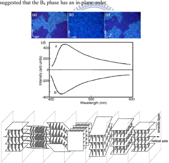
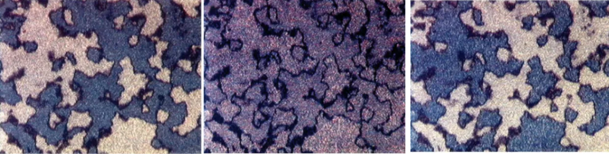
Figure 1.8 The POM textures, CD spectra, and molecular arranged model of B4 phase
9
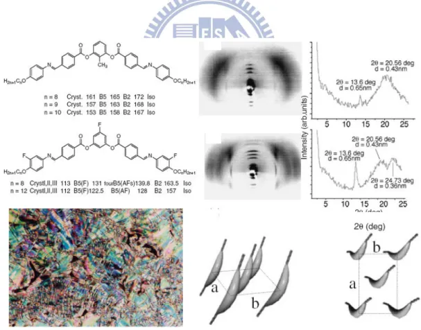
Figure 1.9 The bent-core chemical structures, POM texture, XRD patterns, and molecular arranged models of B5 phase
10
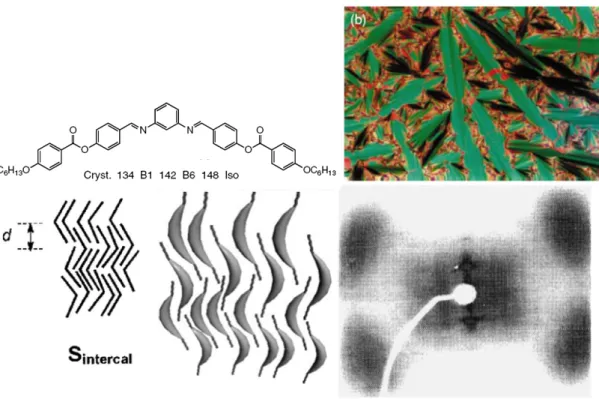
Figure 1.10 The bent-core chemical structures, POM texture, XRD patterns, and molecular arranged models of B6 phase
11
Figure 1.11 The bent-core chemical structures and several kinds of POM textures of B7 phase
12
Figure 1.12 The high resolution XRD patterns, FFTEM image, and molecular arranged model of B7 phase
13
Figure 1.13 The chemical bent-core structure and POM textures of B8
phase
14
Figure 1.14 The definitions of polar switching behaviors of ferroelectric and anti-ferroelectric behaviors
15
Figure 1.15 The identifications of spontaneous polarization behaviors of triangular wave method
16
Figure 1.16 The ferroelectric and anti-ferroelectric response switching current behaviors under normal and modified triangular waves
17
Figure 1.17 The identifications of Racemic/Homochiral Chirality: SmCAPA, SmCSPA, SmCAPF, and SmCSPF.
19
Figure 1.19 The configuration effects of bent-core structures by different central parts on mesophasic varieties
20
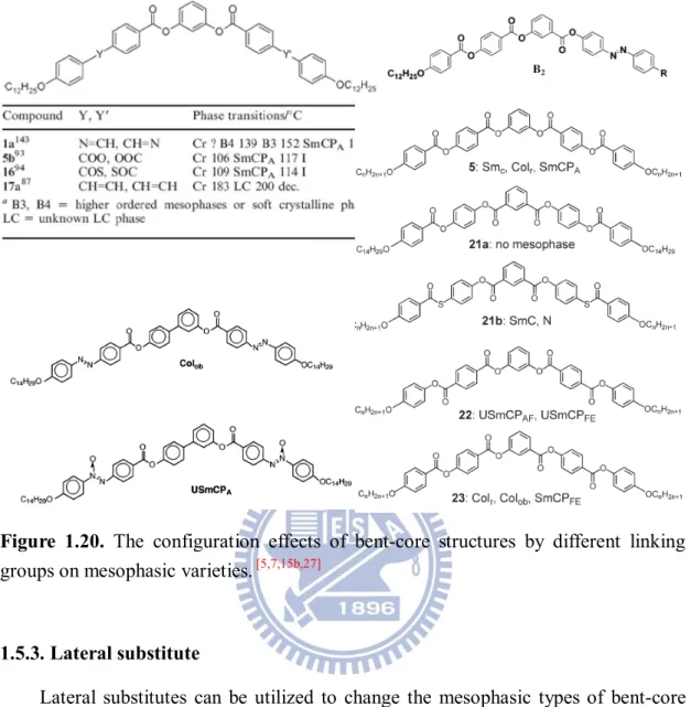
Figure 1.20 The configuration effects of bent-core structures by different linking groups on mesophasic varieties
22
Figure 1.21 The lateral substitute effects of bent-core structures with phenyl and naphthenyl central rings on mesophasic varieties
23
Figure 1.22 The lateral substitute effect for series of bent-core structures bearing different directions of C=N and COO linking groups on varieties of mesophases
24
Figure 1.23 The lateral substitute effects of five-ring bent-core structures with C=C and COO linking groups and six-ring bent-core structures on mesophasic varieties
24
Figure 1.24 The example of bent-core dimers 25
Figure 1.25 The example of bent-core main-chain polymer 26 Figure 1.26 The example of bent-core side-chain polymers 27 Figure 1.27 The example of bent-core dendrimers 27 Figure 1.28 The mesophasic varieties of siloxyl terminal subsituted
bent-core structures depending on various siloxyl terminal linkages and various positions of F lateral substitutes
28
Figure 1.29 The examples of bent-core metallo structures 29 Figure 1.30 The example of the bent-core anocomposited
structures/mixtures and there TEM image
30
Figure 1.31 The examples of bent-core H-bonded structures 31 Figure 2.1 Chemical structures of fully covalent-bonded five-ring
bent-core molecule S12, H-bonded bent-core symmetric trimers (with two H-bonds), and asymmetric dimers (with one H-bond) containing acidic H-donors (Am, Bm, and Cm) and pyridyl H-acceptors (I-II and IIIn-Vn)
35
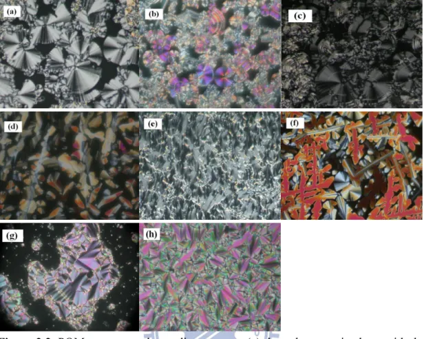
Figure 2.2 POM textures at the cooling process: (a) the polar smectic phase with the spherulite texture of complex IV12-A12 at 96 °C; (b) the polar smectic phase with spherulite and non-specific grainy textures of complex IV12-B16 at 100 °C; (c) the polar smectic phase with spherulite and stripe textures of complex V12-A12 at 100 °C; (d) the Colr phase
with dendritic- and mosaic-like textures of complex V12-B12 at 120 °C; (e) the polar smectic phase with the fan-like texture of complex V16-B16 at 140 °C; (f) the Colr
phase with dendritic- and mosaic-like textures of complex V12-C12 at 130 °C; (g) the smectic A phase with the fan-like texture of complex III16-B16 at 110 °C. (h) the smectic A phase with the fan-like texture of complex III16-A16 at 95 °
Figure 2.3 Phase diagrams (upon 2nd cooling) of asymmetric hetero-dimers: (a) four- and five-ring systems (IIIn-Am, IIIn-Bm, and IVn-Am); (b) six-ring systems (IIIn-Cm, IVn-Bm, and Vn-Am); (c) seven- and eight-ring systems (Vn-Bm and Vn-Cm), and symmetric trimers: (d) five- and seven-ring systems (I-Am and II-Am).
45
Figure 2.4 POM textures at the cooling process: (a) the till smectic phase with spherulite and schlieren texture of complex I-A12 at 100 °C; (b) the till smectic phase with the fan-like texture of complex I-B12 at 130 °C; (c) the undefined smectic phase with the arced fan-like texture of complex I-B12 at 80 °C
46
Figure 2.5 IR spectra of H-bonded asymmetric hetero-dimeric complex V16-B16 (a) at variable temperatures and (b) its composed moieties (at room temperature); H-bonded symmetric trimeric complex I-B16 (c) at variable temperatures and (d) its composed moieties (at room temperature)
49
Figure 2.6 Powder X-ray diffraction intensity against angle profiles obtained upon cooling from the isotropic phase: (a) in the polar smectic phase of complex V16-B16; (b) in the Colr
phase of complex V16-C16
54
Figure 2.7 Switching current responses of H-bonded asymmetric hetero-dimers (a) IV12-A12 at 95 °C (as Vpp = 180 V, f = 60 Hz) and (b) V16-B16 at 130 °C (as Vpp = 120 V and f = 100 Hz) by applying a triangular wave (in parallel rubbing cells with 4.25 µm thickness)
56
Figure 2.8 Ps values as a function of applied voltages (at the SmCP phase as f = 60Hz) for (a) complexes IVn-Am, (b) complexes IVn-Bm, (c) complexes Vn-Am, and (d) complexes Vn-Bm
57
the cooling processes
Figure 2.10 POM textures of the anti-ferroelectric SmCAPA chiral
domain (in a parallel rubbing cell with a cell gap of 4.25 μm) in five-ring complex IV16-A16 by applying d.c. electric fields from (a) -50 V (b) 0 V (c) +50 V; in seven-ring complex V16-B16 by applying d.c. electric fields from (d) -50 V (e) 0 V (f) +50 V. (White arrows are the directions of polarizers and analyzers.)
59
Figure 2.11 Chiral domain textures for complex V16-B16. (Arrows are the directions of polarizers and analyzers.)
59
Figure 2.12 Molecular electrostatic potential mapped on the electron density isosurface of 0.0004 au of the lowest energy structure for the four bent-core structures (a) S1, (b) I-A1, (c) IV1-A1, and (d) III1-B1
61
Figure S2.1 Phase diagram of (a) H-acceptors (Am, Bm, and Cm) and (b) H-donors (I, II, IIIn, IVn, and Vn)
76
Figure S2.2 Ps values vs. applied voltages for compound S12 77 Figure S2.3 Low energy structures of S1 optimized at B3LYP/6-31G(d) 77 Figure S2.4 Low energy structures of I-A1 optimized at
B3LYP/6-31G(d)
78
Figure S2.5 Low energy structures of IV1-A1 optimized at B3LYP/6-31G(d)
78
Figure S2.6 Low energy structures of III1-B1 optimized at B3LYP/6-31G(d)
79
Figure 3.1 The bent-shaped supramolecular frameworks of H-bonded bent-core dimeric and main-chain polymeric (MCP) complexes
84
Figure 3.2 The chemical structures of five diacid H-donors and four pyridyl H-accepters
85
Figure 3.3 H-bonded bent-core dimeric complexes IV-N and V-N (N = A, B, C, D and E)
86
Figure 3.4 H-bonded bent-core main-chain polymeric (MCP) complexes I-N and II-N (N = A, B, C, D and E)
86
Figure 3.5 IR spectra of (a) complexes II-A, V-A and their composed moieties A; (b) complex V-A at variable temperatures; (c) complex II-A at variable temperatures
90
Figure 3.6 POM textures at cooling approach: (a) the tilt smectic phase with spherulite domain of MCP complex I-B at 170
°C; (b) the polar smectic phase with spherulite domain of MCP complex II-A at 147 °C; (c) the polar smectic phase with schlieren texture of MCP complex II-E at 150 °C Figure 3.7 Phase diagrams of H-bonded bent-core (a) dimeric and (b)
MCP complexes during 2nd heating (H) and cooling (C) conditions
93
Figure 3.8 POM textures at cooling approach: (a) the tilt smectic phase with spherulite domain of MCP complex I-B at 170 °C; (b) the polar smectic phase with spherulite domain of MCP complex II-A at 147 °C; (c) the polar smectic phase with schlieren texture of MCP complex II-E at 150 °C
95
Figure 3.9 Powder X-ray diffraction pattern intensity against angle profiles obtained upon cooling from the isotropic phase: (a) in the SmCP phase of dimeric complex IV-E; (b) in the SmCP phase of dimeric complex V-D
99
Figure 3.10 Powder X-ray diffraction pattern intensity against angle profiles obtained upon cooling from the isotropic phase: (a) in the tilt SmC phase of MCP complex I-B; (b) in the SmCP phase of MCP complex II-D
100
Figure 3.11 Switching current response of H-bonded bent-core dimeric complexes (a) IV-A at 104 °C (as Vpp = 231 V, f = 60 Hz) by applying a triangular wave and (b) its POM texture under the corresponding electric field; (c) V-D at 120 °C (as Vpp = 197 V, f = 200 Hz) by applying a triangular wave, and (d) its POM texture under the corresponding electric field; (e) V-D at 120 °C (as Vpp = 197 V, f = 200 Hz) under a modified triangular wave. (in parallel rubbing cells with 4.25 µm thickness)
102
Figure 3.12 Switching current response of H-bonded bent-core MCP complexes (a) II-A at 147 °C (as Vpp = 264 V, f = 200 Hz) by applying a triangular wave and (b) its POM texture under the corresponding electric field; (c) II-E at 120 °C (as Vpp = 327 V and f = 100 Hz) by applying a triangular wave and (c) II-E at 120 °C (as Vpp = 327 V and f = 30 Hz) under a modified triangular wave (in parallel rubbing cells with 4.25 µm thickness)
104
function of cooling temperatures (as f = 200Hz and Vpp = 250 V)
Figure 3.14 Ps values of (a) dimeric complexes V-N (N = A, B, C, D and E) and (b) MCP complexes II-N (N = C, D and E) as a function of applied voltage (as f = 200Hz and (Tc - T) = 10
o
C)
106
Figure 3.15 POM textures of MCP complex II-A under the applied triangular wave electric field as (a) Vpp = 264 V, (b) Vpp = 276 V, (c) vpp = 300 V and (d) Vpp = 0 V (electric field removing)
108
Figure 3.16 POM textures of dimeric complex IV-C under the applied triangular wave electric field as (a) Vpp = 230 V, (b) Vpp = 263 V, (c) Vpp = 296 V and (d) Vpp = 0 V (voltage removing and heating and cooling again); (e) Ps values of dimeric complex IV-C as a function of applied voltage (as f = 200Hz and (Tc - T) = 10 oC)
109
Figure 3.17 The POM textures of chiral domain switching in MCP complex II-A between (a) SmCAPA groundstate with 0 V
(without electric field) and (b) SmCSPF state with ±30 V of
applied d.c. electric field in a parallel rubbing cell with a cell gap of 4.25 μm. (White arrows are the directions of polarizers and analyzers.)
111
Figure 3.18 The co-existence of chiral (SmCSPF) and racemic
(SmCAPF) domains under (a) the first time of the d.c.
electric field applying and (b) second time of d.c. electric field applying (opposite polarities). (White arrows are the directions of polarizers and analyzers.)
112
Figure 3.19 The spherulite domains of dimeric complex V-C: (a) the co-existence of chiral (SmCAPA) and racemic (SmCSPA)
domains without electric field applying; (b) the co-existence of chiral (SmCSPF) and racemic (SmCAPF)
domains under the first time of square wave electric field applying; (c) The decreasing of chiral (SmCSPF) domains,
which transferred to racemic (SmCAPF) domains partially
under third time of square wave electric field applying; (d) The racemic (SmCAPF) domains with the disappearance of
chiral (SmCSPF) domains under fifth time of square wave
electric field applying; (e) the racemic (SmCSPA) domains
without electric field applying; (f) the racemic (SmCAPF)
domains under triangular wave electric field applying; (g) the racemic (SmCAPF) domains after the removing of
triangular wave electric field applying. (White arrows are the directions of polarizers and analyzers, and red arrows are the indicators of chiral (SmCAPA or SmCSPF) domains.)
Figure 3.20 The layer structural models of chirality switching behavior in dimeric complex V-C by five executed switching processes: (a) the initial state with co-existence of SmCSPA
and SmCAPA mixed domains was transferred into (b) the
field-on state of SmCAPF and SmCSPF mixed domains,
where the SmCSPF domains were retained under triangular
wave electric fields (i.e., steps i) but decreased gradually under square wave electric fields (i.e., steps ii). (c) The fully SmCAPF domains (field-on state) were achieved by
applying square wave electric field several times (i.e., steps ii), and switched into (d) SmCSPA domains (field-off state)
were transferred after the electric field removing (i.e., steps iii). Afterwards, the inconvertibly chirality switching of racemic behavior (SmCSPA and SmCAPF) was established
even if the triangular or square wave electric fields were applied (i.e., steps iv). However, the co-existence of SmCSPA and SmCAPA mixed domains were occurred by
heating to isotropic state and cooling to mesophasic state again (i.e., steps v).
116
Figure 3.21 The POM textures of racemic domain switching in MCP complex II-D: (a) SmCAPF ground state under 0 V d.c.
electric field; (b) SmCAPF state under ±50 V d.c. electric
field; (c) SmCAPF state under triangular wave electric field
as Vpp = 140 V in a parallel rubbing cell with a cell gap of 4.25 μm. (White arrows are the directions of polarizers and analyzers.)
117
Figure 3.22 Chiral domain textures of exchange of dark and bright areas in (a) and (b) complex II-B; (c) and (d) complex IV-B; (e) and (f) complex V-B. (White arrows are the directions of polarizers and analyzers.)
118
electric field applying: (a) +100 V; (b) 0 V (voltage removing); (c) - 100 V for complex IV-C with antiferroelectric switching property to show racemic domain (exchanging between SmCSPA and SmCAPF).
Figure 4.1 The chemical structures and formation procedures of bent-core side-chain polymer complexes (AmBn-N) with covalent- and H-bonded components (B and A-N units, respectively)
129
Figure 4.2 NMR spectra of monomers A and B 140
Figure 4.3 NMR patterns of side-chain polymers A1B2 (copolymers), A1B0 (homopolymers), and A0B1 (homopolymers)
141
Figure 4.4 IR spectra of polymer A10B1, pyridyl H-acceptor N, and polymer complex A10B1-N
142
Figure 4.5 POM textures at the cooling process: (a) the tilted smectic phase with schlieren texture of polymer A1B0 at 150 °C; (b) the tilted smectic phase with grainy domain of polymer A10B1 at 150 °C; (c) the nematic phase with schlieren texture of polymer A4B1 at 125 °C; (d) the tilted smectic phase with grainy domain of polymer A1B13 at 130 °C
144
Figure 4.6 Cartoon diagrams of possible intermolecular arrangements of (a) polymers A1B0, A16B1, and A10B1 with larger m/n molar ratios mainly contributed from the self H-bonded acidic dimmers, (b) polymer A4B1 with a medium m/n molar ratio, and (c) polymers A1B2, A1B5, A1B13, and A0B1 with smaller m/n molar ratios mainly contributed from the major component of covalent-bonded bent-cores
145
Figure 4.7 Phase diagrams (upon 2nd cooling) of (a) side-chain polymers AmBn and (b) bent-core side-chain polymer complex AmBn-N
146
Figure 4.8 POM textures at the cooling process: (a) the polar smectic phase with fan-like texture of polymer complex A10B1-N at 130 °C; (b) the tilted smectic phase with grainy domain of polymer complex A1B13-N at 85 °C
147
Figure 4.9 The SmCP phase was introduced by copolymerized frameworks bearing both bent-core covalent- and H-bonded monomers (B and A-N units with proper m/n molar ratios) without the SmCP phase
150
the tilted smectic phase (150 °C); (b) Powder X-ray diffraction intensity against angle profiles at various temperatures upon cooling from the isotropic to crystalline phases
Figure 4.11 Powder X-ray data of polymer complex A16B1-N: (a) 2D pattern in the tilted smectic phase (130 °C); (b) Powder X-ray diffraction intensity against angle profiles at various temperatures upon cooling from the isotropic to crystalline phases
157
Figure 4.12 Switching current responses of polymer complex A10B1-N under (a) the triangular wave method (at Vpp = 310 V, f = 150 Hz, and T = 100 °C) and (b) the modified triangular wave method (at Vpp = 310 V, f = 30 Hz, and T = 100 °C)
160
Figure 4.13 (a) Ps values of polymer complex A10B1-N as a function of applied voltages (at f = 60 Hz and T = 100 °C). (b) Ps values of polymer complex A10B1-N as a function of temperatures (at Vpp = 200 V and f = 200 Hz)
161
Figure S4.1 The single H-bonded five-ring banana-shaped supramolecule (complex H12) and fully covalent-bonded five-ring banana-shaped material (compound S12)
163
Figure S4.2 Powder X-ray diffraction intensity against angle profiles of (a) polymer A1B0 and (b) complex polymer A1B0-N at various temperatures upon cooling from the isotropic to crystalline phases
163
Figure S4.3 Powder X-ray diffraction intensity against angle profiles of (a) polymer A16B1 and (b) complex polymer A16B1-N at various temperatures upon cooling from the isotropic to crystalline phases
164
Figure S4.4 Powder X-ray diffraction intensity against angle profiles of (a) polymer A10B1 and (b) complex polymer A10B1-N at various temperatures upon cooling from the isotropic to crystalline phases
164
Figure S4.5 Powder X-ray diffraction intensity against angle profiles of (a) polymer A4B1 and (b) complex polymer A4B1-N at various temperatures upon cooling from the isotropic to crystalline phases
164
various temperatures upon cooling from the isotropic to crystalline phases
Figure S4.7 Powder X-ray diffraction intensity against angle profiles of (a) polymer A1B5 and (b) complex polymer A1B5-N at various temperatures upon cooling from the isotropic to crystalline phases
165
Figure S4.8 Powder X-ray diffraction intensity against angle profiles of (a) polymer A1B13 and (b) complex polymer A1B13-N at various temperatures upon cooling from the isotropic to crystalline phases
165
Figure S4.9 Powder X-ray diffraction intensity against angle profiles of polymer A0B1 at various temperatures upon cooling from the isotropic to crystalline phases
166
Figure S4.10 Powder X-ray diffraction intensity against angle profiles of (a) polymer AmBn and (b) complex polymer AmBn-N
166
Figure 5.1 Chemical structures of banana-shaped LC H-bonded complexes HPm/CBn and CPm/HBn (where m/n = 15/1, 10/1, 15/1, 1/1, 1/5, 1/10, and 1/15) and their composing H-bonded and covalent-bonded bent-core side-chain homopolymers (HP and CP, respectively) as well as H-bonded and covalent-bonded bent-core small molecules (HB and CB, respectively)
170
Figure 5.2 IR spectra of (a) H-bonded bent-core side-chain polymer complex HP and its components N (H-acceptor) and AP (H-donor homopolymer), and (b) H-bonded bent-core small molecular complex HB and its components N (H-acceptor) and benzoic acid derivative A (H-donor)
175
Figure 5.3 POM textures at the cooling process: (a) the tilted smectic phase with grainy domain and birefringence of H-bonded complex HP5/CB1 at 100 °C; (b) the polar smectic phase with schlieren and fan-like textures of H-bonded complex HP1/CB15 at 90 °C; (c) the tilted smectic phase with birefringence of H-bonded complex CP1/HB5 at 80 °C; (d) the polar smectic phase with schlieren and fan-like textures of H-bonded complex CP1/HB15 at 90 °C
176
Figure 5.4 Phase diagrams (upon 2nd cooling): (a) banana-shaped H-bonded complexes HPm/CBn, consisting of side-chain H-bonded homopolymer HP (i.e., AP-N) and bent-core
covalent-bonded molecule CB; (b) banana-shaped H-bonded complexes CPm/HBn, consisting of covalent-bonded side-chain homopolymer CP and H-bonded small molecular complex HB
Figure 5.5 (a) Powder X-ray 2D pattern of H-bonded complex HP1/CB10 (at 80 °C cooling); (b) Powder X-ray diffraction intensities against angle profiles of H-bonded complexes HP1/CB10 and HP1/CB15 in the polar smectic phase (at 90 °C cooling).
181
Figure 5.6 (a) Powder X-ray 2D pattern of H-bonded complex CP1/HB10 (at 90 °C cooling); (b) Powder X-ray diffraction intensities against angle profiles of H-bonded complexes CP1/HB10 and CP1/HB15 in the polar smectic phase (at 90 °C cooling)
184
Figure 5.7 (a) Switching current responses of banana-shaped H-bonded complex HP1/CB15 (at 80 °C cooling) under the triangular wave method (as Vpp = 240 V and f = 200 Hz). (b) Ps values as a function of applied voltages (as f = 200 Hz) in the SmCP phase of banana-shaped H-bonded complexes HP1/CB15 and HP1/CB10 (at 90 °C cooling)
188
Figure 5.8 (a) Switching current responses of banana-shaped H-bonded complex CP1/HB15 (at 85 °C cooling) under the triangular wave method (as Vpp = 240 V and f = 200 Hz). (b) Ps values as a function of applied voltages (as f = 200Hz) in the SmCP phase of banana-shaped H-bonded complexes CP1/HB15 and CP1/HB10 (at 90 °C cooling)v
189
Figure 5.9 POM textures of the anti-ferroelectric SmCAPA chiral
domain (in a parallel rubbing cell with a cell gap of 4.25 μm, where white arrows are the directions of polarizers and analyzers) in banana-shaped H-bonded complex CP1/HB15 by applying d.c. electric fields from (a) -30 V (b) 0 V (c) +30 V (at 90 °C cooling)
190
Figure S5.1 NMR spectra of monomers A’ and B’ and side-chain H-donor homopolymer AP and bent-core side-chain homopolymer CP
196
Figure S5.2 Powder X-ray diffraction intensities against angle profiles of bent-core side-chain homopolymers HP and CP and
Figure 6.1 The molecular arranged models of complexes Sm/An-x/y, Sm/Bn-x/y, and S16/C12-x/y and their individual covalent- and H-bonded composited chemical structures Sm, An, Bn, and C12
201
Figure 6.2 The POM textures of (a) the complex S12/A12-6/4 in 90 °C and (b) the complex S12/A12-1/9 in 90 °C
205
Figure 6.3 The phase transition temperatures of complexes Sm/An in various molar doping (x/y) ratios
206
Figure 6.4 The SmCP ranges of series of complexes Sm/An in various molar doping (x/y) ratios
207
Figure 6.5 The POM textures of (a) the complex S12/A16-3/7 in 90 °C and (b) the complex S12/A16-7/3 in 90 °C
207
Figure 6.6 The phase transition temperatures of complexes Sm/Bn in various molar doping (x/y) ratios
208
Figure 6.7 The SmCP ranges of series of complexes Sm/Bn in various molar doping (x/y) ratios
208
Figure 6.8 The POM textures of (a) the complex S16/C12-3/7 in 105 °C and (b) the complex S16/C12-6/4 in 90 °C
209
Figure 6.9 The phase transition temperatures of complexes S16/C12 in various molar doping (x/y) ratios
210
Figure 6.10 Powder X-ray diffraction intensities against angle profiles of bent-core complexes S16/A12 with molar doping ratios x/y = 6/4, 7/3, 8/2, and 9/1
211
Figure 6.11 Powder X-ray diffraction intensities against angle profiles of bent-core complexes S16/B16 with molar doping ratios x/y = 2/8, 5/5, and 8/2
213
Figure 6.12 Powder X-ray diffraction intensities against angle profiles of bent-core complexes S16/C12 with molar doping ratios x/y = 2/8, 5/5, and 8/2
214
Figure 6.13 (a) Switching current responses of complex S12/A16-7/3 at 90°C (as V pp = 400 V, f = 60 Hz); (b) the Ps values as a function of molar doping ratio x/y (at the SmCP phases as f = 100Hz) for complexes S12/A12 and S16/A12; (c) the Ps values as a function of molar doping ratio x/y (at the SmCP phases as f = 100Hz) for complexes S12/A16 and S16/A16
216
Figure 6.14 (a) Switching current responses of complex S12/B16-7/3 at 90°C (as V pp = 400 V, f = 60 Hz); (b) the Ps values as a function of molar doping ratio x/y (at the SmCP phases as f
= 100Hz) for complexes S12/B12 and S16/B12; (c) the Ps values as a function of molar doping ratio x/y (at the SmCP phases as f = 100Hz) for complexes S12/B16 and S16/B16 Figure 6.15 Dielectric permittivity studies of (a) the complex
S16/A12-8/2 and its components and (b) the complex S16/B12-8/2 and its components in cooling processes.
218
Figure 6.16 POM textures of the antiferroelectric SmCAPA chiral
domain (in a parallel rubbing cell with a cell gap of 4.25 µm) in the complex S16/B12-7/3 by applying dc electric fields from (a) -100 to (b) 0 to (c) +100 V. (White arrows are the directions of polarizers and analyzers)
219
Figure 6.17 The chiral domain textures of the complex S12/A16-6/4 under applied triangular-wave voltage (Vpp = 180V). During the applied voltage, the observations of chiral domain were revealed via (a) crossed polarizer to (b) and (c) opposite directions of polarizer rotating conditions. The chiral domain was disappeared by the removing of applied voltage
220
Figure S6.1 Powder X-ray diffraction intensities against angle profiles of bent-core complexes S12/A12 with molar doping ratios x/y = 6/4, 7/3, 8/2, and 9/1
222
Figure S6.2 Powder X-ray diffraction intensities against angle profiles of bent-core complexes S12/A16 with molar doping ratios x/y = 6/4, 7/3, 8/2, and 9/1
222
Figure S6.3 Powder X-ray diffraction intensities against angle profiles of bent-core complexes S16/A16 with molar doping ratios x/y = 6/4, 7/3, 8/2, and 9/1
223
Figure S6.4 Powder X-ray diffraction intensities against angle profiles of bent-core complexes S12/B12 with molar doping ratios x/y = 2/8, 5/5, and 8/2
223
Figure S6.5 Powder X-ray diffraction intensities against angle profiles of bent-core complexes S12/B16 with molar doping ratios x/y = 2/8, 5/5, and 8/2
223
Figure S6.6 (a) Switching current responses of complex S16/C12-4/6 at 90°C (as V pp = 300 V, f = 60 Hz). (b) Ps values as a function of applied voltages (at the SmCP phase as f = 60 Hz) for bent-core complexes S16/C12 (x/y = 1/0, 8/2, and
Figure S6.7 Powder X-ray diffraction intensities against angle profiles of bent-core complexes S16/B12 with molar doping ratios x/y = 2/8, 5/5, and 8/2
225
Figure S6.8 Ps values as a function of applied voltages (at the SmCP phase as f = 100 Hz) for bent-core complexes S12/A12 (x/y = 1/0, 9/1, 8/2, 7/3, 6/4, and 5/5)
225
Figure S6.9 Ps values as a function of applied voltages (at the SmCP phase as f = 100 Hz) for bent-core complexes S16/A12 (x/y = 1/0, 9/1, 8/2, 7/3, 6/4, and 5/5)
225
Figure S6.10 Ps values as a function of applied voltages (at the SmCP phase as f = 100 Hz) for bent-core complexes S12/A16 (x/y = 1/0, 9/1, 8/2, 7/3, 6/4, and 5/5)
226
Figure S6.11 Ps values as a function of applied voltages (at the SmCP phase as f = 100 Hz) for bent-core complexes S16/A16 (x/y =1/0, 9/1, 8/2, 7/3, 6/4, and 5/5)
226
Figure S6.12 Ps values as a function of applied voltages (at the SmCP phase as f = 100 Hz) for bent-core complexes S12/B12 (x/y = 1/0, 8/2, 5/5, 2/8, and 0/1)
226
Figure S6.13 Ps values as a function of applied voltages (at the SmCP phase as f = 100 Hz) for bent-core complexes S16/B12 (x/y = 1/0, 8/2, 5/5, 2/8, and 0/1)
227
Figure S6.14 Ps values as a function of applied voltages (at the SmCP phase as f = 100 Hz) for bent-core complexes S12/B16 (x/y = 1/0, 8/2, 5/5, 2/8, and 0/1)
227
Figure S6.15 Ps values as a function of applied voltages (at the SmCP phase as f = 100 Hz) for bent-core complexes S16/B16 (x/y = 1/0, 8/2, 5/5, 2/8, and 0/1)
227
Figure S6.16 Dielectric permittivity studies of (a) the complex S12/A12-8/2 and its components, (b) the complex S12/A16-8/2 and its components, and (c) the complex S16/A16-8/2 and its components in cooling processes
228
Figure S6.17 Dielectric permittivity studies of (a) the complex S12/B12-8/2 and its components, (b) the complex S12/B16-8/2 and its components, and (c) the complex S16/B16-8/2 and its components in cooling processes
Chaper 1
Introduction
1.1. Introduction of Banana-Shaped Liquid Crystals
Ferroelectric and anti-ferroelectric liquid crystals (FLCs and AFLCs) become more important due to their fast response of electro-optical properties by applying external electric fields. At early stages, the molecular design of FLCs was only confined to molecular structures having chiral c enter derivatives. However, since the first example of the achiral bent-core (banana-shaped) molecule possessing switchable behavior has been explored,[1] many kinds of bent-core liquid crystals were developed and conferred fascinating optical and electrical properties.
Banana-shaped liquid crystals, which are the achiral structures, display interesting and special electro-optical properties such as spontaneous polarization and chirality duo to the bent molecular shape and polar linking functions. In general, bent-core mesogenic configurations consist of a central core and two rigid wing segments linking through polar functional groups with a suitable bent angle where appropriate lengths of flexible chains are attached linking groups (see Figure 1.1).[2] According to the bent molecular shape and the polar functions, a total dipole force perpendicular to molecular direction is produced by the coupling of three dimension dipoles (see Figure 1.2), and the spontaneous polarization behaviors of bent-core liquid crystals can be induced through the polar directions of layer structures. Furthermore, the chirality (including racemic and homochiral domains) is also accomplished according to the polar direction and the molecular tilted direction (see Figure 1.3).[3]
1.2. Mesophasic Types of Banana-Shaped Liquid Crystals
Regarding the mesophasic types of banana-shaped liquid crystals, the particular mesophases, including columnar stacking, tilted smectic phases, and three dimensional structures, named as B1 to B8 phases were explored and identified (see Figure 1.4).[3,4] These can be divided into four main types (i) layer modulation, (ii) modification of layer correlation, (iii) helix formation and (iv) splay modulation. The classification of “B phases” has been collected by C. Tschierske and R. A. Reddy as shown inTable 1.1,[5]andthe detail introduction of individual “B phases” is described as following.
Figure 1.2. The dipole direction of bent-core structure.
Figure 1.3. The chirality of bent-core structures according to the polar direction and
Figure 1.4. The mesophasic types of banana-shaped liquid crystals. [3,4]
1.2.1. B1 phase
The B1 phase, which is generally obtained in the bent-core structures with longer
and shorter molecular length ratio of rigid core and flexible chain, respectively, was generalized as a columnar (Col) phase because of the two dimension columnar layer modulation. As shown in Figure 1.5,[6] dendritic-like and mosaic textures were revealable in B1 phase. Based on the traditional identification of B1 phases via XRD
investigations, a broad diffuse scattering peak in wide angle region and several sharp peaks in small angle region were observed. In previous studies, the Colr of B1 phase,
which is the non-tilted columnar arrangement as the undulated wavy molecular stacking, generally exhibited no spontaneous polarization behavior. However, in contrast to the conventional Colr phase, two other kinds of polar switchable B1 phases
named as Colrev and Colob (Colrev,tilt) were developed under a suitable applying of an
electric field, and those different tilted modulated columnar molecular arrangements and 3D structures were shown and compared in Figure 1.5 as well.
Figure 1.5. The mesophase textures, XRD models and molecular arranged models of
B1 phase. [3,6]
1.2.2. B2 phase
The B2 phase (so called SmCP phase) is still the most extensively studied banana
phase. The spontaneous polarization behavior is obtainable in this phase, which is explained the polar order based on close packing of molecules in a smectic layer with a unique bending along a C2V symmetry axis. The schileren, broken fan, and circular
textures were possessed in this phase (see Figure 1.6).[7] The most prevailingly investigated B2 phase revealed ferroelectric (FE)/antiferroelectric (AF) properties,
arrangements with alike/opposite molecular tilted aspects between layer to layer, respectively.[8] Hence, depending on the polar directions and molecular tilted directions in neighboring layers, four kinds of different molecular architectures denoted as SmCAPA, SmCSPA, SmCAPF, and SmCSPF were categorized to homochiral
(SmCAPA and SmCSPF) and racemic (SmCSPA and SmCAPF) conditions, respectively.
In the XRD investigations of B2 phase, the smallest and next-smallest angle peaks are
related to the first and second order diffractions corresponding to the smectic layer with about 30° to 45° molecular tilted angles.
Figure 1.6. The mesophase textures and molecular arranged models of B2 phase. [7]
1.2.3. B3 phase
The B3 phase is a kind of higher-order lamellar arrangement, which often
exhibits in lower temperature cooling from B2 phase (see Figure 1.7). Even if the
spontaneous polarization behavior was received in a previous paper,[9] however the electro-optical identification was uncertainly duo to the non-confirmed second
shown in Figure 1.7, the XRD investigation of B3 phase, revealed several diffraction
peaks at small and wide angle regions to describe it is similar with a crystalline structure,[9,11] and the layer spacing in B3 phase was the same as that in a crystal state,
longer than that in B2 phase, and shorter than that in B4 phase.
Figure 1.7. The bent-core chemical structure and XRD patterns of B3 phase. [3,9,11]
1.2.4. B4 phase
The B4 phase, so called “smectic blue“, often appears in lower temperature
cooling from B2 and B3 phases. In previous studies, the lattice distance of B4 phase
was longer than that of B3 phase. Textures of B4 phase under a polarizing microscope
color was first considered to be caused by selective reflection due to the helical structure like a twist-grain-boundary (TGB) phase.[11,12] In the POM observations of B4 phase, the dark and bright domains were demonstrated, which could be exchanged
by the rotating one of the polarizers clockwise and counterclockwise. A CD spectrum with an opposite sense was also obtained to indicate the chirality structure.[13] Although the B4 phase was not switchable by an electric field and its dielectric
constant was low, SHG was observed even without the electric field. This indicated the existence of a spontaneous non-centrosymmetric order.[4] In the XRD investigations of B4 phase (see Figure 1.8), the number of diffraction peaks decreased
in wide angle region and the peaks became wider than that of B3 phase, which
suggested that the B4 phase has an in-plane order.
1.2.5. B5 phase
According to the previous articles, B5 phase was performed in the bent-core
structures which bear CH3 and F substitutes at the central-ring and the F substitute at
both terminal rings (see Figure 1.9).[14] In previous studies, this phase appeared below the B2 phase, and the transition enthalpy between them was small. In electro-optical
studies, the FE and AF switching of spontaneous polarization behaviors in B5 phase
were observable. Even if the electro-optical properties and mesophase texture of B5
phase were similar with those of B2 phase, however their XRD investigations from the
surface oriented samples were distinguishable. In a small angle region, highly order reflections peaks corresponding to the smectic layer spacing could be observed. Moreover, the model of in-plane molecular arrangement was established as well.
Figure 1.9. The bent-core chemical structures, POM texture, XRD patterns, and
1.2.6. B6 phase
As shown in Figure 1.10, the B6 phase exhibited a fan-like texture as the smectic
A phase but a homeotropic texture could never be obtained. In XRD investigations, only one reflection peak smaller than half of molecular length was obtained in the small angle region to indicate the intercalated molecular arrangement tilted in a layer. In addition, four broad diffuse peaks were observed in the wide angle region, suggesting liquid-like in-plane order.[15]
Figure 1.10. The bent-core chemical structures, POM texture, XRD patterns, and
molecular arranged models of B6 phase. [3,15]
1.2.7. B7 phase
Based on the previous articles, the B7 phase often revealed in the bent-core
structures with a NO2 or CN substitutes at the positions of central ring.[16] Many kinds
of POM textures could be observed in B7 phase such as spiral filament (coexistence of
shown in Figure 1.11.[4,17] The FE and AF switching of spontaneous behaviors in B7
phase were obtainable. In XRD investigations, a liquid-like broad diffuse peak and several sharp reflection peaks were obtained in wide and small angle regions, respectively, and the sharp reflection peaks were also identified by the high resolution X-ray diffraction, suggesting the 2D ordered modulated layer structures. The immediate image of modulated layer structures was also observable by freeze fracture transmission electron microscopy (see Figure 1.12).[18] On the other hands, the B7
phase was called SmCG phase within triclinic symmetry as well. Depending on tilting
of the molecular planes (called clinic) and of the layer polarization (called leaning) where the layer polarizations further exhibited in-layer and out-layer conditions, eight different general tilted structures were framed as shown in Figure 1.12.[19]
Figure 1.11. The bent-core chemical structures and several kinds of POM textures of
Figure 1.12. The high resolution XRD patterns, FFTEM image, and molecular
arranged model of B7 phase. [3,18,19]
Figure 1.13. The spiral and fan-like domains were examined in this phase by gradual and further cooling from isotropic phase, respectively. The AF switching of spontaneous behaviors in B7 phase was obtainable, and the bi-layer structure was also
recognized by XRD investigations.[20]
In recent years, some kinds of mesophases such as nematic, smectic A, and crystalline phases, which displayed their own spontaneous switching behaviors and chirality were discovered in novel bent-core liquid crystals (those properties are not contributed form chiral-center possessed rod-like structures). It is suggested that the original “B phase” classified rules may be not satisfied for subsequently researches. Otherwise, complete classification of the Bn-related phases is a subject for future
research.
1.3. Identifications of AF/FE Spontaneous Polarizations in B
2Phase
In this dissertation, we focus the mainly researches in the investigations and characterizations of the B2 phase of bent-core structures. The electro-opticalproperties are deservedly the important investigations for banana-shaped liquid crystals. Regarding the spontaneous polarization behaviors of B2 phase, the equal and
opposite polar directions between layer to layer micro-polar directions are detected. As shown in Figure 1.14, two kinds of polar switching conditions were defined.[21] The ferroelectric (FE) switching behavior means a polar smectic ground state (SmPF1)
with equal inter-layer polar directions switches to a reverse polar smectic excited state (SmPF2) with equal inter-layer polar directions under a sufficient applied electric field.
On the other hands, the anti-ferroelectric (AF) switching behavior means a polar smectic ground state (SmPAF) with opposite inter-layer polar directions switches to
the polar smectic excited state with equal inter-layer polar directions. Then, the spontaneous polarization behaviors can be enhanced due to the inter-molecular micro-aggregation of AF/FE polar switching conditions.
Figure 1.14. The definitions of polar switching behaviors of ferroelectric and
anti-ferroelectric behaviors.
In general, those polar switching behaviors have been determined by using a
SmP
F1SmP
F2peaks per half-period of an applied triangular voltage were obtained in the switching current response curves. Here, the characteristic behavior of a sequential electric response was due to a ferroelectric state switches into an antiferroelectric ground state and back to the opposite ferroelectric state, which was confirmed the SmCPAF
structure of the B2 phase. Single current peak per half-period of an applied triangular
voltage was acquired in switching current response curves, indicating that a sequential electric response was due to a ferroelectric state switches into the opposite ferroelectric state, which confirms the SmCPFE structure of the B2 phase. In addition,
the AF/FE behaviors have been further proved by an applying modified triangular wave as well.[23] The switching current peaks of AF behavior would be separated to two peaks, which situate at the start and the end locations of zero potential. However, only one switching current peak of FE behavior was displayed at the start or end locations of zero potential. This method can be applied to confirm the too fast switching of unobvious AF state clearly and avoid the erroneous judgment of fake FE behavior (AF behavior with a hidden AF state in normal triangular wave supplying).
Figure 1.15. The identifications of spontaneous polarization behaviors of triangular
![Figure 1.1. The molecular formation of bent-core liquid crystalline designs. [2]](https://thumb-ap.123doks.com/thumbv2/9libinfo/8362508.176926/31.892.160.739.512.1069/figure-molecular-formation-bent-core-liquid-crystalline-designs.webp)
![Figure 1.7. The bent-core chemical structure and XRD patterns of B 3 phase. [3,9,11]](https://thumb-ap.123doks.com/thumbv2/9libinfo/8362508.176926/37.892.144.757.283.838/figure-bent-core-chemical-structure-xrd-patterns-phase.webp)