Fast sequential decoding algorithm based on
dynamic searching strategy
C.-Y. Lee W.-W. Yang
L.-F. Jeng
Indexing terms: Decoding algorithm, Decoding e$ciency, Dynamic searching strategy
Abstract: The authors present a new sequential decoding algorithm based on dynamic searching strategy to improve decoding efficiency. The searching strategy is to exploit both ‘sorting’ and ‘path recording’ techniques. By means of sorting, it is possible to identify the correct path in a very fast way and then, by path recording, the bit sequence can be recovered without degrading decoding performance. The authors also develop a conditional resetting scheme to overcome the buffer overflow problem encountered in conven- tional sequential decoding algorithms. Simulation results show that, for a given code, the decoding efficiency remains the same as that obtained from maximum likelihood function by appropriately selecting sorting length and decoding depth. In addition, this algorithm can easily be mapped onto an area-efficient VLSI architecture to imple- ment long constraint length convolutional decoders for high-speed digital communications.
1 Introduction
Convolutional coding with Viterbi decoding is widely accepted as an efficient method to achieve a significant power gain on digital communication channels with low to moderate signal-to-noise ratios. Generally speaking, for information bit rates greater than 5 Mbits/s, the decoder must be based on a fully parallel implementation of the Viterbi algorithm, which often demands one com- plete cycle in each clock interval; that is, one set of input symbols is processed and one output bit presented in each clock interval. The speed requirements impose timing constraints on each module in the decoder which normally consists of three parts: an input module, an addxompare-select (ACS) module and a path storage and selection (PSS) module. The most severe constraints are found in the latter two modules, where the ACS module depends on the constraint length v and the PSS module relies on both constraint length and decoding depth d. Thus as v becomes large, the hardware complex- ity increases considerably and hence the design cost becomes huge or even not feasible for present technology. Due to this consideration, it is very often found that the
~~ ~ ~ _ _ _ _ _ _ _ _ _
0 IEE, 1994
Paper 14661 (E5), first received 27th September 1993 and in revised
form 28th June 1994
The authors are with the Department of Electronics Engineering, National Chiao Tung University, 1001, University Road, Hsinchu, 300, Taiwan, Republic of China
312
constraint length is limited, say 7, in many available hardware solutions found in the literature [ 1-31.
Alternatively, sequential decoding [4, 51 has low com- putation complexity in search of a correct path. However, the decoding rate decreases because a correct path can only be identified after several trials on incorrect paths due to error bits. The principal sequential decoding algo- rithms are due to Fano [4] and the stack-based algo- rithm due to Felinek [6]. Although these algorithms are useful for longer constraint length codes, they suffer from ‘buffer overflow’ which derives from an inability to main- tain uniform decoding rates while searching message sequences. Previously, we presented a dedicated memory structure [7] to speed up the decoding rate. However, the problem of buffer overflow still remained. We recently developed a new high-speed data sorter [8] which pro- duces a sorted sequence immediately after input samples are given. This technique provides a very powerful hard- ware solution for those applications which require massive sorting operations. In principle, sequential decoding algorithm can be regarded as a set of sorting operations working on the survived nodes to identify a possible candidate node. From this candidate node further tracking can be performed until all input sequences are decoded. This modified sequential decod- ing is called a ‘fast sequential sorter decoding’ (FSSD) algorithm. In this paper a path recording technique is developed to overcome back-tracking of correct bit sequences and to improve throughput rate. Simulation results obtained from this algorithm are provided to illus- trate the decoding efficiency of this modified algorithm. Finally, we present an efficient VLSI architecture for single-chip implementation of the developed algorithm. It is found that the constraint length is not limited by this proposed architecture and hence it is very suitable for long constraint-length applications.
2 Fast sequential decoding algorithm
The sequential decoding method is one of the alternative$ for convolutional decoder designs. Traditional sequential decoding algorithms either use ‘threshold’ or ‘stack’ to select a correct path for back tracking of input sequences. There are, however, some drawbacks in using these
This work was supported by the National Science Council of Taiwan, ROC, under Grant NSC82-F- SP-009-01. The authors would also like to thank their colleagues within the SI2 group of the National Chiao Tung University for many fruitful suggestions and discussions.
approaches. For the threshold scheme, each candidate node is sequentially checked until a path, whose accumu- lated cost* or weight, is beyond any specified threshold. This may require several trials on incorrect paths before the correct path is found. Moreover, selecting the thresh- old is not easy since it relies heavily on channel noise levels. For stack based sequential decoding, a stack often suffers the buffer overtlow problem, which leads to the irrecoverability of the correct path. In addition, both types (threshold and stack) also require back tracking of the correct paths to recover all correct bit sequences. Therefore, many operations are still needed in back tracking, although fully parallel comparisons on trellis diagrams are not required.
The modified sequential decoding algorithm presented here is derived from the concept of the stack approach. It is more efficient in its search for the correct path because a sorter is exploited to identify the most probable node from which node expansion or path tracking is per- formed. Moreover, in this paper we develop a new tech- nique called ‘path recording’ to keep track of the path information so that, after a predefined depth d is reached, the correct decoded bit sequence is automatically pro- duced. In the following, we discuss first how these two techniques are applied for performance improvement and then provide some simulation results of the FSSD algo- qithm.
2.1 Sorter kernel
At the outset we assume that both hard decision and soft decision methods can be handled. However, to make this algorithm more readable, we consider only the hard deci- sion method and use constraint 3 and rate 1/2, i.e. the (2, 1, 3) code, as an example to illustrate the decoding process.
The code generator is given in Fig. la. First we con- struct the trellis diagram indicating the diverting path at
I path:
-
b
Fig. 1 A (2, I , 3) encoder a Example
b Corresponding trellis diagram
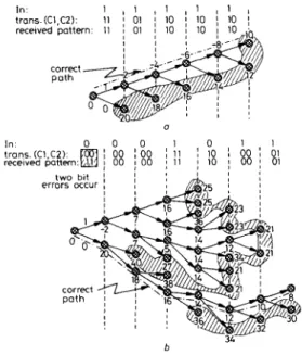
each node as shown in Fig. lb. For correct transmission of one bit, the cost will be decreased by -1, while for incorrect transmission, the cost will be increased by 10 if p is 3%
[SI.
Thus, one of three different costs (-2, 9, 20) * Here, the cost represents the branch matrix and is determined by error transmission probability p over the binary symmetrical channel(BSC).
I E E Proc.-Commun., Vol. 141, No. 5, October I994
will be added to each diverted node according to the difference between transmitted and received patterns. For example, if ‘10’ is transmitted and ‘11’ is received, then the cost to be added becomes 9.
If an error-free channel is considered, the correct path can easily be identified if we follow the node based on the minimum weight as shown in Fig. 2a. It can be found
31.
b
Fig. 2
scheme, illustrated for the (2, I , 3) code given in Fig. I a Noise-free situation
b Noise effect
Note that the mask area indicates the surviving nodes to be stored after decoding a certain bit sequences. It can be concluded that more storage space is needed lor transmission on nony channel
Search of the correct path by the fast sequential sorter decoding
that tracking the correct path is now formulated as a sorting scheme working on the weights of all survived nodes. If we start from the root and select the node with the less cost of the two candidate nodes, we can always find the correct path and hence the transmitted sequence can be fully recovered. Thus it is not necessary to track all nodes as those required in the maximum likelihood function since only the node with minimum weight is needed for each decoded bit.
Now, an error-free channel does not exist in real-life applications. As shown in Fig. 26, where two error bits occur consecutively, the correct path cannot be immedi- ately identified because of lower weights resulting from the error bits. In this case, if the decoding depth is taken further, the weight from the incorrect path becomes higher than that of the correct path. Then, after certain steps of bit decoding, we can move back to the correct path and continue estimating the weights of nodes on the correct path. This implies that a sorter can be used here to track the minimum weight of the surviving nodes. If no errors occur, only the node with the minimum weight is replaced by the new node which inherently has the new minimum weight. The other node is placed in a certain position according to its weight. If only one error occurs, we arbitarily select one, e.g. a ‘1’ path, from two diverting paths since both nodes have the same cost, say 9 in our example. The first element is deleted and then both new weights are inserted at the neighbouring positions 313
according to their sorted order. If, by luck, we select the correct path, then the weights of this path decrease; otherwise, after tracking several nodes on incorrect paths, the ‘0’ path will then be selected as shown in Fig. 2b. By the above process, we found that the search for the correct path can be formulated as a sorter-based scheme again. In other words, if we always start from the minimum weight, we can speedily identify the correct path, even if there is a noise-effect. Thus, this sorter-based scheme may be summarised as follows.
(i) Reset the weights of all nodes and start the cost estimation from root.
(ii) Use the weight of the first element to generate two new weights and record the decoded bit; in the mean time, extract the decoded bit sequence when the prede- fined depth is reached.
(iii) Sort the weights of all nodes according to ascending sequence.
(iv) If the input sequences are not terminated, then go back to step (ii) for bit decoding; otherwise output the decoded bit sequence.
Since sorting requires a lot of operations, we can reduce this computation complexity by checking the error pat- terns. If one error bit is detected, we only have to sort once since both candidates have the same weight. But, if no error bits or two error bits are detected, we can replace the first element by the new minimum weight and then insert the other weight according to its sorted order. In this way, the required sorting operations ca? be reduced by half. In summary, the aproach is to dynamic- ally search for the node with the minimum weight from the surviving tree nodes.
2 2 Speed up decoding process by path recording The above process focuses on the identification of the current path by sorter-based operations. Even so, it still requires some effort to obtain the recovered bit sequence. After the correct path is identified, we need to back-track for a certain depth d because of the limit of storage space in the sorter. This back-tracking strategy often requires the use of extra storage space and hence cost generation and accumulation becomes idle or another storage unit is needed to speed up the performance.
Fortunately, the back-tracking strategy can be avoided because, when a candidate node is selected, we already know that either ‘0’ or ‘1’ path is assigned to this node as shown in Fig. 3. Thus each node is already combined
bit order1 path information
1
I?
t
lengt h, L
produce decoded pattern
/
Fig. 3 Illustration of the path recording scheme
with a possible decoded bit information. The new bit sequence is obtained by shifting up the old bit sequence and inserting one bit (either ‘1’ or ‘0’). Then, this new sequence is written to the position as identified by the sorter. The path information identified by the minimum 314
weight is shifted up one bit and then conditionally loaded into the output buffer. Therefore, if the decoding depth d is taken appropriately, the correct bit can be obtained from the path recorder identified by the first element of the sorter while the weight calculation can still be per- formed simultaneously. The path-recording strategy is very efficient in generating the correct bit sequence since no back-tracking is needed.
It should be noted too that the decoded bit obtained from the path recorder relies on the condition that the depth d should be reached before it is passed to the output buffer. This is to ensure that all bits obtained are from the correct path. However, since in the decoding process, part of the surviving nodes are from incorrect paths and may temporarily stay at the first position of the sorter. If we always extract the bit sequence from the first element, error bits will be inserted into the output bit sequence. Therefore we must ensure that output bits can be extracted from the path recorder only when the speci- fied depth d is reached. To do this, a status register, which specifies the order of output bit sequence, can be employed. The status register serves two purposes: (i) for the address to access the input buffer when input bit pat- terns are to be detected again, i.e. when path tracking from the surviving nodes has to be performed and (ii) for depth detection to see if the specified depth is reached.
By combining both sorting and path recording tech- niques we can search the correct path and obtain the output bit sequence in a very efficient way. Fig. 4 shows the results for these two techniques, where the data are based on the path search given in Fig. 2a. Clearly, the three important parameters are updated simultaneously. Each time, when a new node is detected, one more space is created to record the required information, such as decoded bit order, new weight and path information. No. of Sorted Decoded Recorded
traced weight bit path nodes sequence order information
1 - 2 1 20 1 2 - 4 2 18 2 20 1 3 -6 3 16 3 18 2 20 1 4 -8 4 14 4 16 3 18 2 20 1 5 -10 5 12 5 14 4 16 3 18 2 20 1 1 0 11 10 0 111 110 10 0 1111 1110 110 10 0 11111 11110 1110 110 10 0
. . .
. . . .. . .
. . . Fig. 4path search given in Fig. 2a
Illustration ofthe sorting and path recording techniques for the
2.3 Straregy to improve coding gain
Two issues are to be considered here: (i) the finite preci- sion and finite length problem and (ii) the relation between decoding depth and sorter length.
In some cases the decoding process will fail because a loop is detected or the new generated weight cannot be
stored in the sorter due to burst errors. In this case, the weights of survived nodes are almost the same as illus- trated in Fig. 5a, which implies that some important
sorter 1enath.L one error + 9 a 192
119212561256(216125612561--12561256)256)
one error + 9 Fig. 5D Weights of surviving nodes remlun almost the same so that new weight cannot be stored in the case of I bit-error
b Removing path loss by resetting strategy to allow new weights be stored Path loss due t o burst errors
LY W
m
SN R
Fig. 8
depth d, where sorter length L and S N R are adjustable
-0- 128
-*-
96-0- 64 -A- Viterbi
Simulation results in t e r m of bit error rate (BER)for a f i r e d
paths can never be recovered. Therefore, the new pro- duced weights cannot be stored in the sorter and hence a loop is detected or a path is lost. To solve this problem we apply a reset method to initialise the decoding process by using current decoded bit sequences. This is per- formed by resetting the sorter content, as done in the initial phase, so that the most recent nodes can be stored. We can use the previous decoded bit sequences to ensure that correct codes are generated for comparison as shown in Fig. 5b. In the meantime, the finite precision and length problem can be solved using this reset strategy.
The relation between sorter length (L) and decoding depth (d) of path recoder can be determined by an iter- ative process. Here L represents the sorter capacity indic- ating how many surviving nodes can be stored and handled. Depth d represents that correct bits can be obtained during path tracking. Since these two param- eters are very related and dependent on channel noise level, we assume first that a very long L is used and then determine a depth d for correct bit decoding at different IEE Prac-Commun., Vol. 141, N o . 5 , October 1994
noise levels. Then, based on a selected depth d, we reduce the length L until bit error rate (BER) is above a certain level. a W m (z W m Fig L -96 2.0 2.5 3.0 3.5 ' 4.0
'
' 4.5 5.0 a'"Ol
10-11 L.128 2.0 2.5 30 3 5 40 I 4 5 5.0 EblNo.dE b7 Simulation results for afixed sorter length L, where path depth d and S N R are adjustable
Sorber depth: -m- IS -0- 21
-*-
21 -0- 33 2.4 Simulation resultsFig. 6 shows the BER of L against SNR at a fixed depth
d. For a selected channel with known error probability p . a convolutional code is first determined and then both L and d can be estimated. Fig. 7 shows the BER of d against SNR at a fixed L. It is found that d should be at least four or five times the constraint length to ensure that correct path can be recovered. Note that we have included a commercial chip from Qualcomm [9] in Fig. 6 for comparison. Results show that the performance of our algorithm is better than that from Viterbi decoding algorithm when L and d are selected appropriately. These simulation results are similar to those found in Reference 10. In addition, this algorithm is also useful for long con- straint length since only L and d have to be adjusted. For example, if SNR = 3 dB and a (2, 1,7) code are assumed, the best L of the sorter is selected as 96 for a depth d of 27 when the BER is to be less than That is only the first 96 elements are considered to be the candidate (surviving) nodes for tracking the correct path. If L is less than 96, probably the BER will be higher than lo-'.
3 VLSI architecture
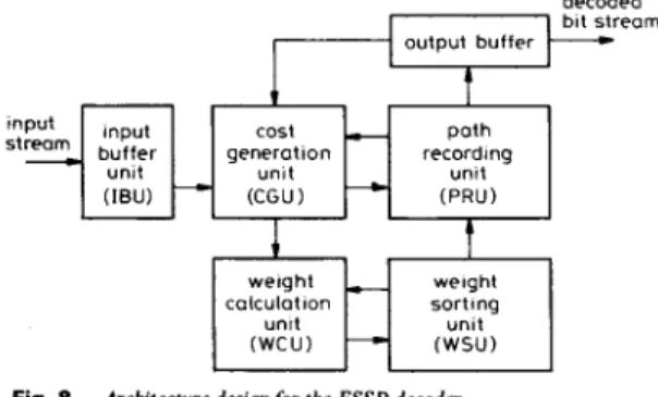
The proposed algorithm can be mapped onto a shift register based architecture which can meet high- throughput requirements. The architecture consists of several functional units as shown in Fig. 8. For example, decoded
input
buffer generation
Fig. 8 Architecture design for the FSSD decoder
the input buffer unit (IBU) contains the encoded sequences. The weight calculation unit (WCU) uses the node with minimum weight as a basis and then calculates the new weight according to the two costs which are gen- erated by the cost generation unit (CGU). The cost is obtained by pattern matching and then produces a pair of two costs. The weight sorting unit (WSU) is used to store the weights of the survived nodes. The path record- ing unit (PRU) is provided to produce the correct bit sequence when the depth is reached and, in the mean time, to give a label indicating the order of decoded bits. It can be found that both PRU and WSU occupy most of the area (at least 96 x (16
+
8) cells are needed). They can be realised on shift register arrays. For example, the detailed architecture for the PRU is given in Fig. 9. TheI
t
shift leftlright register array porollel bit sequencet-
I - r Iaddress incrementer d e c o d ~ i ~ & ‘ a b e l
I
U-
Fig. 9 Detailed architecture of the path recording unit
first element of the PRU should record all the path infor- mation and possible decoded bit sequence with the maximum number up t o the specified depth d. It is con- nected to an up shifter whose LSB is injected with ‘0’ or ‘1’ depending on the path to be detected. In addition, a status register labelling the order of the decoded bit sequence is needed for two purposes. One is to trace back bit patterns of the survived nodes when an incorrect path is detected. This implies that the status content should be sent to the IBU to load input pattern for path 316
tracking. Thus, all status registers should be reset in the initial phase and the content of the first element should be incremented by ‘1’ when a new decoded bit is deter- mined. The other is to detect whether the depth d is reached. To reach this goal, the content from this status register has to be compared with the specified depth to generate a load control signal to conditionally govern whether the MSB of the up shifter should be stored in the output buffer. Again normalisation should be done here because of finite precision problem. We use a dynamic matching technique to reach this goal. That is, in the initial phase, the depth is stored in the detection register. When the content of the first status register is the same as the content of the detection register, the shift-out MSB should be stored in the output buffer. Then both status and detection registers are simultaneously incremented by ‘1’.
With this efficient architecture, not only can high- speed be achieved but also programmability for different constraint length can be handled. A prototype chip based on the proposed algorithm and architecture for a (2,1,7) code has been implemented and tested. Its decoding speed can be up to 25 Mbits/s, where the core area is 4.3 mm x 4.5 mm using a commercial 0.8 pm CMOS double metal process [ll].
4 Conclusion
A new sequential decoding algorithm for high-speed digital communications has been presented. The use of both sorting and path recording techniques not only solves the low-throughput problem but also provides a solution for long constraint convolutional code designs when mapped onto shift register array architecture. Thus a cost-effective solution for high-speed convolutional codes can be achieved. The proposed technique can also be applied to trellis codes and rate-k/n convolutional codes for video distribution and high-speed communica- tion links. We are currently developing a prototype VLSI chip to implement the proposed algorithm for HDTV and high-speed networking applications.
5 References
1 ISHITANI, T., TANSHO, K., MIYAHARA, N., KUBOTA, S., and KATO, S.: ‘A scaroe-state-transition Viterbidecoder VLSI for bit
error correction’, IEEE J . Solid-state Circuits, Aug. 1987, 22, (4), pp. 575-581
2 COGGINS, D.J., SKELLERN, D.J., KEANEY, R.A., and NICOLAS, J.J.: ‘A comparison iof path memory techniques for VLSI Viterbi decoders’. Proc. VLSI’89, Munich Germany, Aug. 1989, pp. 378-388
3 PAASKE, E., PEDERSEN, S., and SPARSO, J.: “An area-efficient path memory structure for VLSI implementation of high-speed Viterbi decoders’, Integr. VLSI J., 1991, pp. 79-91
4 FANO, R.M.: ‘A heuristic discussion of probabilistic decoding’, IEEE Trans. Inform. Theory, 1963, IT-9, pp. 64-73
5 VITERBI, AJ., and OMURA, J.K.: ‘Principles of digital communi- cation and coding’(McGraw-HiU, New York, 1979)
6 FELINEK, F.: ‘Fast sequential decoding algorithm using a stack‘, IBM J . Res. Develop., Nov. 1969, 13, pp. 675-685
7 LEE, C.Y., CATTHOOR, F., and DE MAN, H.: ‘Breaking the bottleneck of sequential decoding for high-speed digital communica- tion’. Proc. ICASSP, Toronto, May 1991
8 LEE, C.Y., TSAI, I.M., and HSIEH, P.W.: ‘High-speed median filter designs using shiltable content address memory’. To appear in IEEE Trans. Circults Syst. Video Technol.
9 QUALCOMM, Inc., ‘41650 product description’. San Diego, CA
1990
10 GOULD, T.M., and HARRIS, J.H.: ‘Single-chip design of biterror- correcting stack decoders’, IEEE J . Solid-State Circuits, May 1992, 27, (SA pp. 76&775
11 YANG, W.W., and LEE, C.Y.: ‘High-speed sequential decoder designs using shirtable content addressable memory’. Submitted to
APCCASP4,5-8 Dec., 1994, Taipei, Taiwan