國 立 交 通 大 學
電信工程研究所
碩 士 論 文
具多封包接收能力無線網路之媒體存取控
制及適應性調變和編碼之聯合最佳化
Joint Optimization of Medium Access Control and
Adaptive Modulation and Coding for Wireless
Networks with Multipacket Reception
研 究 生:劉士淵 Student: Shih-Yuan Liu
指導教授:李大嵩 博士 Advisor: Dr. Ta-Sung Lee
具多封包接收能力無線網路之媒體存取控制及適應性
調變和編碼之聯合最佳化
Joint Optimization of Medium Access Control and
Adaptive Modulation and Coding for Wireless Networks
with Multipacket Reception
研 究 生:劉士淵 Student: Shih-Yuan Liu
指導教授:李大嵩 博士 Advisor: Dr. Ta-Sung Lee
國立交通大學
電信工程研究所
碩士論文
A Thesis
Submitted to Institute of Communication Engineering
College of Electrical and Computer Engineering
National Chiao Tung University
in Partial Fulfillment of the Requirements
for the Degree of
Master of Science
in
Communication Engineering
June 2010
Hsinchu, Taiwan, Republic of China
具多封包接收能力無線網路之媒體存取控制及
適應性調變和編碼之聯合最佳化
學生:劉士淵
指導教授:李大嵩 博士
Chinese Abstract
國立交通大學電信工程研究所碩士班
摘要
多封包接收(MPR)已被視為一種可有效增加無線網路容量的技術。然而, 在結合適應性調變編碼(AMC)的無線通訊網路中,傳統的多封包接收矩陣已無法 反應真實的物理層(PHY)特性。若將 AMC 機制直接加入 MPR 的環境中,由媒體 存取控制(MAC)層所選到的使用者及其相對應的傳輸模式可能非為最佳,這將使 得 PHY 的 MPR 能力無法完全發揮。在本論文中,吾人提出一跨層式(cross-layer) 設計將所選之使用者及其相對應的傳輸模式做一聯合最佳化,使得 MAC 層在做 排程程序時可將 PHY 的 MPR 能力完全發揮。模擬結果顯示吾人所提出的方法 較其他將 AMC 機制直接加入 MPR 環境的次佳方法有著較佳的表現。Joint Optimization of Medium Access Control and
Adaptive Modulation and Coding for Wireless
Networks with Multipacket Reception
Student: Shih-Yuan Liu
Advisor: Dr. Ta-Sung Lee
English Abstract
Institute of Communication Engineering
National Chiao Tung University
Abstract
Multipacket reception (MPR) has been recognized as an effective technique to enhance the capacity of wireless networks. However, the traditional MPR matrices cannot reflect the channel dynamics in modern wireless communication networks, where adaptive modulation and coding (AMC) mechanisms are adopted to improve the system performance. If AMC mechanisms are directly incorporated into MPR environments, the selected users and the associated transmission modes may not be optimal for the medium access control (MAC) layer to fully exploit the MPR capabilities of the physical layer. In this thesis, we propose a cross-layer design to jointly optimize the user selection and the corresponding modes, which can fully exploit the MPR capabilities when the MAC layer performs the scheduling procedure. Computer simulations show that the proposed method outperforms other suboptimal AMC methods, where AMC is directly incorporated into MPR environments.
Acknowledgement
I would like to express my deepest gratitude to my advisor, Dr. Ta-Sung Lee for his enthusiastic guidance and great patience, especially in the training of presentation. I learned a lot from his positive attitude in many areas. Thanks are also offered to all members in the Communication System Design and Signal Processing (CSDSP) Lab. Last but not least, I would like to show my sincere thanks to my family and my lovely girlfriend for their invaluable love and support.
Table of Contents
Chinese Abstract ... II
English Abstract ... III
Table of Contents ... V
List of Figures ...VII
Acronym Glossary ... IX
Notations ... X
Chapter 1 Introduction ... 1
Chapter 2 System Model and Problem Formulation... 4
2.1 System Scenario...5
2.2 MPR Channel Matrix...6
2.3 Adaptive Modulation and Coding...9
2.4 Multi-Group Priority Queuing MAC Protocol ...12
2.5 Summary ...14
Chapter 3 MPR MAC Protocol with Adaptive Modulation and
Coding ... 15
3.1 Motivation...16
3.2 Proposed Joint AMC-MAC Design ...21
3.3 Proposed Joint AMC-MAC Design with MGPQ MAC Protocol...24
3.4 Computer Simulations ...25
Chapter 4 Enhanced Joint AMC-MAC Design... 34
4.1 Proposed Probability Based Mode Tuning Method ...35
4.2 Proposed Enhanced Joint AMC-MAC Algorithm ...36
4.3 Proposed Enhanced Joint AMC-MAC Design with MGPQ MAC Protocol .37 4.4 Computer Simulations ...39
4.5 Summary ...43
Chapter 5 Conclusions and Future Works... 44
List of Figures
Fig. 2-1 Network model of the uplink centralized wireless network ...5
Fig. 2-2 Mechanism of adaptive modulation and coding...10
Fig. 2-3 Throughput contribution of adopted modes corresponding to different SINR... 11
Fig. 2-4 Packet format of MGPQ MAC protocol...12
Fig. 2-5 The priority grouping process by central controller within three time slots ...13
Fig. 3-1 Dialogue of PHY and MAC through MPR matrix...16
Fig. 3-2 Flow chart of directly incorporating AMC into MPR environment...17
Fig. 3-3 Network deployment of 8 users in grid distribution ...17
Fig. 3-4 Throughput comparison between Suboptimal AMC and Mode 1...18
Fig. 3-5 Throughput comparison between Suboptimal AMC and Mode 2...20
Fig. 3-6 Packet loss rate comparison between Mode 2 and SubAMC of near/far users...20
Fig. 3-7 Joint AMC-MAC design...21
Fig. 3-8 Concept of reverse design from MAC to PHY ...23
Fig. 3-9 Throughput comparison between Joint AMC and suboptimal methods for Case 1 (SNR_max = 20 dB, SNR_min = 16 dB)...27
Fig. 3-10 Delay comparison between Joint AMC and suboptimal methods for Case 1 ...27
Fig. 3-11 Throughput comparison between Joint AMC and suboptimal methods of Case 2 (SNR_max = 13 dB, SNR_min = 9 dB)...28
Fig. 3-12 Throughput comparison between Joint AMC and suboptimal methods for Case 3 (SNR_max = 30 dB, SNR_min = 26 dB) ...29
Fig. 3-13 Network deployment of 24 users in grid distribution ...30
Fig. 3-14 Throughput comparison between Joint AMC and suboptimal methods for Case 4 (M = 24, SNR_max = 28 dB, SNR_min = 16 dB) ...31
Fig. 4-1 Enhanced Joint AMC-MAC algorithm...37
Fig. 4-2 Throughput comparison among Enhanced JAM and other methods for Case 1...39
Fig. 4-3 Throughput comparison among Enhanced JAM and other methods for Case 2...40
Fig. 4-4 Throughput comparison among Enhanced JAM and other methods for Case 3...41
Fig. 4-5 Throughput comparison among Enhanced JAM and other methods for Case 4...42
Fig. 4-6 Throughput comparison among Enhanced JAM and other methods for Case 5...42
Fig. 4-7 Loss recovery of Enhanced Joint AMC compared with Suboptimal AMC (3) and (4) for Case 5 ...43
Acronym Glossary
ACK acknowledgement AMC adaptive modulation and codingCC central controller
CDMA code division multiple access
OFDMA orthogonal frequency division multiple access MGPQ multi-group priority queueing
GMPR generalized multi-packet reception ID identification
MAC medium access control
PHY Physical layer
MPR multiple packet reception PSP packet success probability QoS quality of service
SPR single packet reception
JAM Joint AMC-MAC
EJAM Enhanced Joint AMC-MAC PBMT Probability Based Mode Tuning
Notations
C the generalized MPR channel matrix M total number of users
U the user set
i
u the index of user i
η capacity of a MPR channel 0
n the number of transmitted packet to achieve the channel capacity p packet generating probability
i
P received signal power from user i
p
T throughput when the packet generating probability is p AMC
C AMC incorporated GMPR matrix AMC
CM transmission mode matrix AMC
η channel capacity of AMC incorporated MPR environment
0,AMC
Chapter 1
Introduction
Recently, cross-layer design and optimization of wireless networks have drawn a lot of attention [1-8]. Since traditional wireless networks are designed based on a layered approach, the systems usually operate far away from the theoretical limits. For example, the medium access control (MAC) protocols are designed without considering the properties of the physical (PHY) layer. On the other hand, the PHY layer resources and capabilities are usually only partially exploited because of the separate design from MAC layer. Therefore, it is important for a system engineer to develop a cross-layer approach to mitigate the gap between PHY and MAC and further achieve the goal of efficient management of the system resources.
Effective MAC mechanisms are characterized by high throughput and low delay. Traditionally, the design of MAC protocol is based on the so-called collision channel model which only supports one simultaneous transmission. In the collision model, all the channel effects such as fading and noise are ignored, i.e. the packet reception is assumed to be error-free. In addition, it also under-utilizes the capability of the PHY layer to successfully decode multiple packets in the presence of simultaneous transmissions. For example, in IEEE 802.11-based wireless local area networks (WLANs), although the PHY layer is quipped with advanced signal processing
techniques, it still adopts the collision channel model as the MAC model. With advanced PHY layer signal processing techniques, it is possible for central controllers (CC) to detect multiple concurrently transmitted packets through, e.g. multiuser detection (MUD).
Recently, a new MAC channel model called multipacket reception (MPR) draws increasingly attention. Several proposals of MAC protocols for MPR environments have been reported in the literatures [9-16]. In this kind of model, a reception matrix is used to model such a channel, and the number of successfully received packets is modeled by a random variable that depends on the number of simultaneous attempted transmissions. There are several possible solutions for enabling MPR, e.g. deployment of adaptive antenna arrays, code division multiple access (CDMA), multi-input multi-output (MIMO) technology and orthogonal frequency division multiplexing (OFDM). Through an MPR channel, the central controller (CC) can receive two or more packets at the same time. The throughput performance is improved compared to the MAC protocol with single packet reception (SPR) capability.
Due to the enhancement of the spectral efficiency and link robustness, adaptive modulation and coding (AMC) has been widely adopted as an efficient technique in the PHY layer of several standards [17, 18]. Traditionally, AMC refers to the concept of adjusting modulation order and coding rate dynamically to different channel conditions. When the channel is good, higher-order modulation and higher coding rate are used; when channel is bad, robust but less efficient lower-order modulation and lower coding rate are chosen. In [19], an AMC link adaptation algorithm that adjusts transmission parameters such as rate and power over time-varying channels is proposed to improve the system performance. Recently, many cross-layer designs about analyzing the joint effects of AMC and other techniques are proposed. In [20], the effects of finite-length queuing on AMC are studied. Several proposals about
combining MIMO and AMC have been reported in the literatures, e.g. deadline constrained traffic [21], queuing analysis [22], dynamic adaptation between diversity and multiplexing modes [23].
However, all of the previous MPR works do not take the AMC mechanism into consideration such that the traditional MPR matrix cannot reflect the channel dynamics in modern wireless communication networks, where AMC mechanisms are used to improve the system performance. Therefore, the extracted information from the traditional MPR matrices may not be correct. This may cause the user selection and the corresponding modes non-optimal and make it impossible to fully exploit the MPR capability of the physical layer. In this thesis, our design objective is to perform a cross-layer design by jointly optimizing the user selection and the associated transmission modes, which makes the MPR capability being fully exploited during the scheduling process. However, in previous MPR works, all the selected users are assumed active to send packets, which may be improper when the traffic is low. Hence, we further propose an enhanced design which takes traffic conditions into consideration and provides chances to the selected users to be reassigned higher order transmission modes, which may be more proper to the actual traffic conditions.
The remainder of the thesis is organized as follows. In Chapter 2, we give a brief review on the system model of MPR channels, AMC mechanism and the MGPQ MAC protocol with MPR capability. The first proposed Joint AMC-MAC (JAM) method will be described in Chapter 3. Theoretical throughput will be analyzed and given along with simulation results. The second proposed Enhanced JAM with Probability Based Mode Tuning (PBMT) method will be described in Chapter 4. This new scheme is developed based on the findings in Chapter 3. Performance analysis and simulation results of the proposed approaches are illustrated in this chapter. Finally, we summarize
Chapter 2
System Model and Problem
Formulation
In this chapter, we present the model of a communication network with MPR capability. There are three basic components in this communication network: users, common wireless channel, and the central controller (CC). The transmission data format of each user in this network is equal-sized packet. Transmission time is slotted here and each packet requires one time slot to be transmitted. In typical cases, the CC does not know the buffer state of users from the feedback information. For the conventional collision channel, a transmission is successful only if there is just one user trying to send data with other users being idle at the same time slot. As for MPR channels, different from collision channels, packets could be successfully received even there are more than one simultaneous transmission. To utilize the MPR capability efficiently, complicated user state estimation algorithms are required. The modulation-coding pairs (transmission mode) of users are assigned by CC at the beginning of transmission. There are two adopted transmission modes which can be assigned to users based on their channel conditions, which are represented by their SINRs (signal to interference and noise ratio). In Section 2.2, we will firstly present the MPR channel model. In Section 2.3 an introduction to the AMC mechanism is
described. Some related previous studies are introduced in Section 2.4. The Multi-Group Priority Queuing (MGPQ) protocol is presented in Section 2.5, which is adopted to be the MPR MAC protocol in this thesis with the advantage of not requiring active user detection and further improving the system throughput. A summary of Chapter 2 is given in Section 2.6.
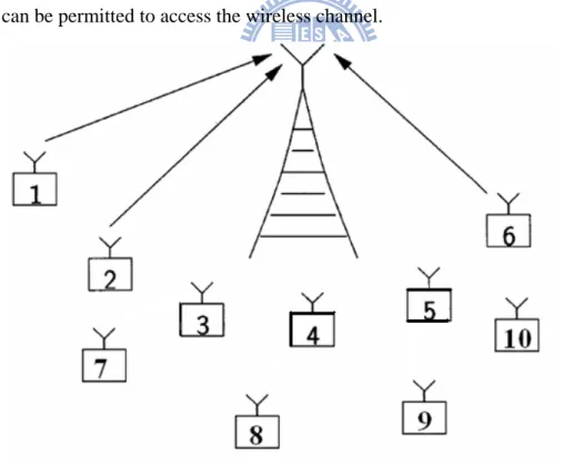
2.1 System Scenario
Consider the uplink of a centralized wireless network in which there are totally M users who transmit data to CC through a common wireless channel as illustrated in Fig. 2-1. We assume that the transmission time is slotted, and the CC controls which user can be permitted to access the wireless channel.
Fig. 2-1 Network model of the uplink centralized wireless network
The adopted MGPQ MAC protocol is proposed which adds one tail flag-bit to indicate if the next buffer has the user’s own packet to transmit [13, 14]. The added
flag-bit has the advantage to provide explicit information about the incoming traffic condition, which makes the selected accessing users be more probable to have packets to transmit instead of wasting bandwidth on those users who have no packets to transmit. At the beginning of each time slot, the CC determines the access set according to some user scheduling rule and assigns each selected user’s transmission mode, and then broadcasts this information to the network to initialize the data transmission. According to the result of packet reception, CC will broadcast ACK or NACK to all users. According to ACK or NACK, users could decide to discard those successful transmitted packets or to keep those packets which are not successfully received.
2.2 MPR Channel Matrix
MPR channel matrix is a great tool that is a bridge of communication between the physical layer and the MAC layer. It transforms the properties of the physical layer to a simple matrix which provides important information for The physical layer to perform scheduling procedure. Let 1~M denote users’ IDs. Then the generalized MPR (GMPR) channel matrix can be expressed as
( ) ( ) ( ) ( ) ( ( )) ( ) ( ) ( ( )) ( ( )) ( ) ( ) ( ( )) ( ( )) ( ( )) 1,0 1,1 2,0 2,1 2,2 ,0 ,1 ,2 , C M M M M M C U t C U t C U t C U t C U t U t C U t C U t C U t C U t ⎡ ⎤ ⎢ ⎥ ⎢ ⎥ ⎢ ⎥ ⎢ ⎥ = ⎢ ⎥ ⎢ ⎥ ⎢ ⎥ ⎢ ⎥ ⎣ ⎦ , (2.1)
where the user set U t( )=
{
u t1( ), u t2( ), , uM( )t}
,( )
{
1, 2, ,}
i
mechanism such as priority sorting [13, 14]. For 1≤ ≤n M and 0≤ ≤k n , ( )
[
packets are correctly received packets from first users in are transmitted]
, . n k C =P k n n U t Denotes ( ) ( ) , ( ( )) 1 n n n k k C U t k C U t =
∑
(2.2)the expected value of correctly received packets when the first n packets from ( )
{
1( ), 2( ), , ( )}
n n
U t = u t u t u t are transmitted. The capacity of an MPR
channel for the particular U t is defined as
( )
( )(U t ) maxC U tn( ( ))
η . (2.3)
Note that the numbers of simultaneously transmitted packets to achieve the channel capacity may not be unique. Let
( )
( )
{
( ( ))}
0 min arg maxn 1,...,M n
n U t C U t
= (2.4)
be the optimal number of capacity-achieving accessing users. The system throughput will degrade with other number of selected users to access the channel. If the selected number of users is less than n U t , the MPR capability is not fully exploited, and 0( ( )) if more than n U t users are selected, the additional interference may make the 0( ( )) channel capacity decrease.
The general model for MPR channels given in (2.1), it can be applied to many systems, such as spread spectrum, antenna array or sophisticated signal-processing-based packet separation schemes [25]. It can also be used to describe some special cases such as conventional collision channel or channels with capture effect. The reception matrix of conventional collision channel can be represented by
0 1 0 0 1 0 0 0 1 0 0 0 ⎡ ⎤ ⎢ ⎥ ⎢ ⎥ ⎢ ⎥ ⎢ ⎥ ⎢ ⎥ ⎢ ⎥ ⎢ ⎥ ⎢ ⎥ ⎣ ⎦ . (2.5)
It can be seen that a transmitted packet can be successfully received only if there is no other concurrent transmissions. The MPR matrix can be determined via the properties of the physical layer such as bit error probability and coding rate. An illustrative example of a CDMA cellular network system will be given as follows [10, 13]. The CDMA cellular network is expressed as the standard Gaussian approximation (SGA) shown below. Let U denote the subset consisted of the first n nodes of n U t ,
( )
then the bit error probability (BEP) can be represented by
( )
{ } 2 3 BEP 3 n j n k k U j j G U Q P G P σ ∈ − ⎛ ⎞⎟ ⎜ ⎟ ⎜ ⎟ ⎜ ⎟ ⎜ ⎟ ⎜ = ⎜ ⎟⎟ ⎜ + ⎟⎟ ⎜ ⎟ ⎜ ⎟⎟ ⎜⎝∑
⎠ , (2.6)where G is the processing gain, P is the received signal power transmitted by user k. k
Each packet contains Lp bits, and a block error control code is used to correct up to t
errors in each received packet. The noise component is modeled as the additive white Gaussian noise with variance denoted by σ . We can characterize these physical 2 layer’s properties with a reception matrix C U t constructed as follows. Under the ( ( )) assumption that errors occur independently to every packet, the packet success probability (PSP) with the presence of interfering packets is
( )
( )
( )
0 PSP BEP 1 BEP p t p l L l j n j n j n l L U U U l − = ⎛ ⎞⎟ ⎜ ⎟⎡ ⎤ ⎡ ⎤ ⎜ = ⎜ ⎟⎟⎣ ⎦ ⎣ − ⎦ ⎜ ⎟ ⎝ ⎠∑
. (2.7) Thus, we have ( )(
( )
( )
)
, , PSP 1 PSP n n n k j j n j U j n U k C U U U ∈Ψ ∈ −Ψ Ψ⊂ Ψ = ⎡ ⎤ =∑
Π Π ⎣ − ⎦ . (2.8)After calculating each Cn k, (U t , the reception matrix ( )) C U t can be fully ( ( )) constructed. As mentioned before, the reception matrix C U t serves as an ( ( )) interface between the physical layer and the MAC layer. Many physical layer parameters such as correlation of the spreading codes, error control codes, fading characteristics of the channel and background noise all affect the elements of
( )
( )
C U t . After the physical layer is totally characterized by the reception matrix ( )
( )
C U t , the issues about how to design a MAC protocol which utilizes the reception capability of the physical layer efficiently become important.
2.3 Adaptive Modulation and Coding
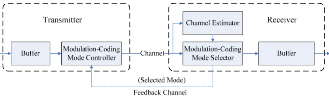
The objective of AMC mechanism in the physical layer is to maximize the data rate by adjusting transmission parameters to the different available channel conditions, which are characterized by each user’s SINR. In conventional AMC works [19-20], there is a certain algorithm to segment the SINR axis (from 0 to infinity) with thresholds to be the criterion of mode selection for attaining some goals, e.g. maintaining a prescribed packet error rate in every mode segmentation [20]. After those mode thresholds of AMC are determined, each user’s modulation-coding pair (transmission mode) is adaptively assigned with the feedback information from receiving side after the channel estimation procedure. The AMC flow could be depicted in Fig. 2-2. The modulation-coding pairs adopted in this thesis are given in Table 2-1.
Fig. 2-2 Mechanism of adaptive modulation and coding
Table 2-1 Adopted modes in this thesis
Mode 1 2
Modulation QPSK 16-QAM
Coding rate 1/2 3/4
When AMC is incorporated in the MPR environment, every user’s SINR depends on the calculated number of optimal accessing users, i.e. n U t . With 0( ( ))
( )
( )
0
n U t , the SINR of user i can be calculated by (2.9): ( ) ( ) 0 SINRi i n U t i i j j i S S I N S N ≠ = = + +
∑
. (2.9)Unlike conventional AMC works, there is no particular algorithm to segment the SINR axis as in this thesis. The basic idea of mode assignment here is to calculate every user’s average contribution to the system throughput. After each user’s SINR is calculated, CC assigns the mode maximizing the user’s contribution to the throughput, which can be calculated by multiplying the user’s coding rate by the packet success probability (PSP) under the certain SINR. The reason of this mode assignment criterion is that although those modes with higher coding rate could have higher percentage of data in a packet, the packet success probability would be lower since its error controlling capability is weaker; however those modes with lower coding rate
might not possess high data percentage, they do have higher packet success probability. The relation between SINR and contribution to throughput of the adopted modes is depicted in Fig. 2-3.
Fig. 2-3 Throughput contribution of adopted modes corresponding to different SINR
In Fig. 2-3, it can be observed that there exists a crossing point between the two modes. Therefore if a user’s SINR is given, the suitable transmission mode for the user could be decided simply by checking Fig. 2-3, e.g., if a user’s SINR is higher than the crossing point (about 6.7 dB), the suitable mode would be mode 2 to attain a high data rate; on the other hand, if the SINR is lower than the SINR of the crossing point, the suitable mode should be mode 1 to guarantee the user have higher packet success probability with stronger error controlling capability.
2.4 Multi-Group Priority Queuing MAC
Protocol
In this section, the basic idea of MGPQ protocol proposed in [13] applied in this thesis as the MAC protocol is introduced. Relying on a simple flag-assisted mechanism and an associated multi-priority user grouping strategy, the search for the active users is avoided and hence the computational complexity is significantly reduced. Through the use of a single flag-bit, the scheme provides the deterministic knowledge about the incoming network traffic while the incurred overhead due to the insertion of this flag-bit is rather small. In MGPQ MAC protocol, the users are allowed to access the channel according to the prescribed service priority. Users are assigned to three groups (PREM, ACTIVE, and STANDBY) according to the priority grouping mechanism and then the active set can be determined automatically. The packet blocking constraint is relaxed and the throughput performance is further improved.
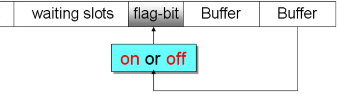
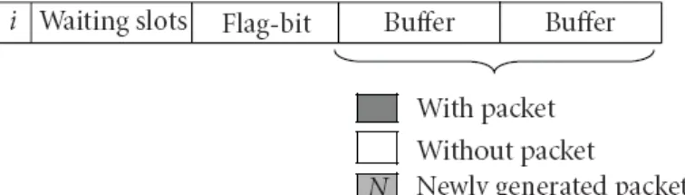
Fig. 2-4 shows the schematic packet formats of the MGPQ MAC protocol, the first part represents user ID, second part counts the number of waiting slot, third part marks the on/off status of the flag-bit, fourth and fifth parts represent the contents of buffers.
A simple illustrative example is shown in Fig. 2-5 to depict the operation of the MGPQ MAC protocol in three consecutive time slots.
Fig. 2-5 The priority grouping process by central controller within three time slots
From the example in Fig. 2-5, the MGPQ MAC protocol can be summarized as below.
Central controller:
I. Put all users into the PREM group.
II. Select first n U users (by the order of PREM, ACTIVE, and then 0( ) STANDBY group) to access the channel.
a) If the packet of a certain user is received successfully, then put the user to the tail of the ACTIVE (if the flag bit is on) or STANDBY group (if the flag-bit is off). And reset its count of waiting slots to zero.
transmitted but not successfully received, and then put the user back to the tail of the STANDBY or ACTIVE group in which the user originally stayed. Reset its count of waiting slots to zero.
III. Increase waiting slots of all users by one.
IV. Move those users with waiting slots equal to S to the PREM group. V. Repeat steps II to IV.
2.5 Summary
The basic ideas about MPR channel model and AMC mechanism are introduced in this chapter. Speaking of AMC scheme at the physical layer, instead of considering it separately from higher layer techniques, i.e. ARQ, queuing, many researches pursue cross-layer designs that incorporates AMC with those higher layer techniques to improve the overall system performance. Many MAC protocols exploiting the MPR capability at the physical layer are designed to maximize the per-slot throughput. However, the issue about reducing computational complexity is still important. For reducing the complexity of finding active users, MGPQ MAC protocol is proposed with a simple flag-assisted mechanism and an efficient multi-priority user grouping strategy to sort the users into three groups (PREM, ACTIVE, and STANDBY). Hence the set of accessing users can be determined automatically via the grouping strategy. In this thesis, the basic idea we considered is also a cross-layer design that incorporates AMC with MPR MAC protocols to assure that the transformed properties of the physical layer represented by the MPR matrix could be fully exploited during MAC scheduling procedure. The detailed discussion will be introduced in the following chapters.
Chapter 3
MPR MAC Protocol with Adaptive
Modulation and Coding
In this chapter, we introduce the Joint AMC-MAC (JAM) algorithm. First, some simulation results are shown to highlight the performance issue of directly incorporating AMC into MPR networks. The new Joint AMC-MAC algorithm is proposed to jointly optimize user set selection and the corresponding assigned modes, which can fully exploit the packet reception capabilities of the physical layer. The analytic results reveal that the throughput performance is improved compared with those suboptimal methods, i.e. directly incorporating AMC into MPR environments. In Section 3.1, the motivation of this thesis is described and some simulations are shown. The proposed Joint AMC-MAC design is introduced in Section 3.2. In Section 3.3, the proposed Joint AMC-MAC design with MGPQ MAC protocol is summarized. Section 3.4 contains the numerical results of the proposed method, and Section 3.5 summarizes this chapter.
3.1 Motivation
In previous MPR works [8, 25, 26], AMC mechanisms are not considered, so the formulation of the MPR matrix is static due to the constant modulation and coding rate as shown as a conceptual diagram in Fig. 3-1.
Fig. 3-1 Dialogue of PHY and MAC through MPR matrix
The constant MPR matrices [13] cannot reflect the channel dynamics in modern wireless communication networks, where AMC mechanisms are used to improve the system performance. If the AMC mechanism is directly applied to conventional MPR environments, the determined user-mode set, i.e. the selected accessing user set and the corresponding assigned transmission modes, might be non-optimal, such that the multipacket reception capabilities of the physical layer cannot be fully exploited.
The procedure of incorporating AMC into MPR environments is summarized as follows, and the corresponding flow chart is given in Fig. 3-2.
1. Form the MPR matrix by one of the adopted modes and calculate n0 by (2.3) 2. Calculate each selected user’s SINR by (2.9).
3. Assign every user’s mode by the mechanism depicted in Section 2.3.
4. Perform Multi-group priority queuing MAC protocol with the selected user-mode set.
Fig. 3-2 Flow chart of directly incorporating AMC into MPR environment After assigning modes, the average throughput contributed by these selected users could be calculated. With the simulation results, we will show that the selected user-mode set determined through this direct flow may not attain the achievable channel capacity from AMC incorporation.
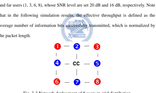
We consider a CDMA network with randomly generated spreading codes. Eight users are deployed in a grid distribution as in Fig. 3-3. CC is located in the middle of the grid distribution. The users can be regarded as two groups: near users (2, 4, 5, 7) and far users (1, 3, 6, 8), whose SNR level are set 20 dB and 16 dB, respectively. Note that in the following simulation results, the effective throughput is defined as the average number of information bits successfully transmitted, which is normalized by the packet length.
Fig. 3-3 Network deployment of 8 users in grid distribution
Case 1:
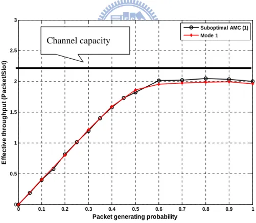
The parameters of the MPR matrix formulation are based on Mode 1, which means that all users’ default transmission modes are set to Mode 1. After all selected users’ SINRs are calculated; those users with higher SINRs will be switched to Mode 2. The numerical result of this case is shown in Fig. 3-4.
In Fig. 3-4, the line labeled as channel capacity is the attainable channel capacity when AMC is incorporated into the MPR environment, which can be calculated as (3.7). It can be observed that the curve labeled as Suboptimal AMC, AMC directly applied to the MPR environment, doesn’t improve the system throughput in a significant way compared with the Mode 1 (AMC is not incorporated). The reason of this situation is that the formed MPR matrix based on Mode 1 inherently informs the CC that this environment allows for a strong packet reception capability. Therefore the calculated n0 will be large, making those selected users’ SINR levels too low to be switched to Mode 2. In other words, the AMC mechanism will not be actually activated in this case because all the selected users’ SINRs are too low, which is due to that the CC selects too many users to simultaneously access the channel.
0 0.1 0.2 0.3 0.4 0.5 0.6 0.7 0.8 0.9 1 0 0.5 1 1.5 2 2.5 3
Packet generating probability
E ff e c ti v e t h roug hpu t ( P a c k e t/ S lot ) Suboptimal AMC (1) Mode 1
Fig. 3-4 Throughput comparison between Suboptimal AMC and Mode 1 Channel capacity
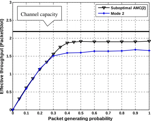
Case 2:
The parameters of the MPR matrix formulation are based on Mode 2, which means that all users’ default transmission modes are set to Mode 2. After all selected users’ SINRs are calculated, and those users with lower SINR will be switched to Mode 1. The numerical result of this case is shown in Fig. 3-5.
As in Case 1, the Suboptimal AMC and Mode 2 in Fig. 3-5 represent the cases in which AMC is applied and not applied, respectively. It can be observed that applying AMC can improve the system throughput because the AMC mechanism adjusts the modes of those lower SINR users to Mode 1, which guarantees that they can obtain a higher packet success probability. This can be verified by Fig. 3-6, which shows that the average packet loss rate of the far users (user 1,3,6,8 in Fig. 3-3) is improved by AMC. However, even though the throughput performance is improved in Fig. 3-5 by directly incorporating AMC, it still cannot attain the channel capacity.
By the two cases, we can find out that if AMC is directly incorporated into MPR environment, either no improvement to the system throughput or limited throughput could be achieved. Both cases imply that the packet reception capabilities of the physical layer are not fully exploited by the direct incorporation of AMC into MPR environment, which means that the selected accessing user set and the assigned transmission modes are non-optimal. Thus, a Joint AMC-MAC algorithm is proposed to fully exploit the MPR capabilities by a simple iterative procedure which optimizes the user selection and the associated transmission modes. The algorithm will be introduced in next section.
0 0.1 0.2 0.3 0.4 0.5 0.6 0.7 0.8 0.9 1 0 0.5 1 1.5 2 2.5 3
Packet generating probability
E ff ect ive thr o ughput ( P acke t/ S lot ) Suboptimal AMC(2) Mode 2
Fig. 3-5 Throughput comparison between Suboptimal AMC and Mode 2
0 0.1 0.2 0.3 0.4 0.5 0.6 0.7 0.8 0.9 1 0 0.1 0.2 0.3 0.4 0.5 0.6 0.7 0.8 0.9 1
Packet generating probability
P ack et l o ss r at e Mode 2 (Far) SubAMC(2)(Far) Mode 2 (Near) SubAMC(2)(Near)
Fig. 3-6 Packet loss rate comparison between Mode 2 and SubAMC of near/far users Channel capacity
3.2 Proposed Joint AMC-MAC Design
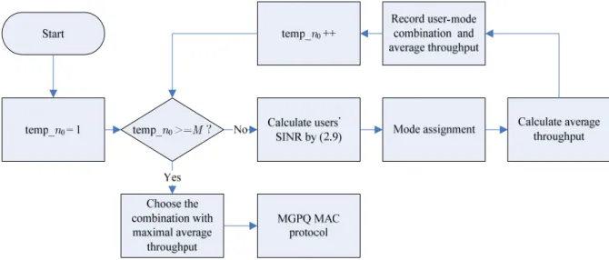
The basic idea of the proposed method is a reverse design from MAC to PHY because other previous MPR works are based on a “PHY to MAC” concept as depicted in Fig. 3-1. The term “PHY to MAC” means that the MAC scheduling procedure works based on the information from PHY, i.e. n0 and channel capacity. In this thesis, we start from the MAC layer, trying to find the optimal accessing user set selection and the corresponding transmission modes, and then the MAC layer reversely tells the physical layer that which transmission mode should be adopted to fully exploit the MPR capabilities. The method designed to achieve this objective is a simple iterative procedure which tries every possible combination of user set and modes to find the user-mode combination that maximizes the average system throughput, which is defined as the optimal accessing user-mode set. After the optimal user-mode set is obtained, we perform the scheduling procedure with the selected users and the corresponding modes. The flow chart of the method is given in Fig. 3-7
The proposed Joint AMC-MAC could form a matrix as in (3.1), which is similar to the GMPR matrix as in (2.1). Denote
( ) ( ) ( ) ( ) ( ) ( ) ( ( )) ( ) ( ) ( ( )) ( ( )) 1,1 2,1 2,2 AMC ,1 ,2 , M M M M C U t C U t C U t U t C U t C U t C U t ⎡ ′ ⎤ ⎢ ⎥ ⎢ ′ ′ ⎥ ⎢ ⎥ ⎢ ⎥ = ⎢ ⎥ ⎢ ⎥ ⎢ ′ ′ ′ ⎥ ⎢ ⎥ ⎣ ⎦ C (3.1) and ( ) ( ) ( ) ( ) ( ) ( ) ( ( )) ( ) ( ) ( ( )) ( ( )) AMC 1,1 2,1 2,2 ,1 ,2 , M M M M TM U t TM U t TM U t U t TM U t TM U t TM U t ⎡ ⎤ ⎢ ⎥ ⎢ ⎥ ⎢ ⎥ ⎢ ⎥ = ⎢ ⎥ ⎢ ⎥ ⎢ ⎥ ⎢ ⎥ ⎣ ⎦ CM (3.2)
as the GMPR matrix incorporated with AMC and the corresponding mode matrix, respectively; where , ( ( )) ( ) 1,2,...
max
n k c m C U t R m = ′ = ⋅Pr{k user’s packet in th U t is ( )correctly received using mode i| n packets from first n users in U t are ( ) transmitted}, i.e. the maximal average throughput contributed by user i, R i is the c( ) coding rate of mode i, and m is the index of modes. TMn k, (U t in (3.2) records ( )) the associated transmission mode of the kth user in U t when the first n users in ( )
( )
U t are selected. Since the AMC mechanism is incorporated into the MPR environment, the calculation of (2.6), (2.7) and (2.8) are slightly different. Let U n denote the subset consisted of the first n nodes of U t , then the bit error
( )
probability (BEP) can be represented by(
)
( ) ( ) ( ) { } 2 3 BEP , 3 n j n k k U j j G m N m U m Q P G m P σ ∈ − ⎛ ⎞⎟ ⎜ ⎟ ⎜ ⎟ ⎜ ⎟ ⎜ ⎟ ⎜ = ⎜ ⎟⎟ ⎜ + ⎟⎟ ⎜ ⎟ ⎜ ⎟⎟ ⎜⎝∑
⎠ , (3.3)N(m) is the normalizing factor such that the received SNR of each constellation size is the same, P is the received signal power transmitted by user k. Each packet k
contains Lp bits, and a block error control code is used to correct up to t(m) errors in
each received packet. t(m) can be calculated from [10, 27]
( ) 1 log2( ) (1 )log 12( ),
c
R m = +α α + −α −α (3.4)
( )
( )
where α = 2t m +1 /Lp. The packet success probability (PSP) in (2.7) becomes
(
)
( )( )
( )
0 PSP , BEP 1 BEP p t m p l L l j n j n j n l L U m U U l − = ⎛ ⎞⎟ ⎜ ⎟⎡ ⎤ ⎡ ⎤ ⎜ = ⎜ ⎟⎟⎣ ⎦ ⎣ − ⎦ ⎜ ⎟ ⎝ ⎠∑
. (3.5) And (2.8) becomes: ( ) ( ) ( )(
)
, 1,2,... PSP ,max
n k c j n m C U t R m U m = ′ = ⋅ (3.6)As in GMPR matrix, the channel capacity and the corresponding number of accessing users can also be calculated from (3.7) and (3.8), respectively.
( ) ( ) ( ( )) AMC U t maxC U tn η ′ , (3.7) where ( ( )) , ( ( )) 1 n n n k k C U t C U t = ′
∑
′ . And ( ) ( ) ( ( )) 0,AMC 1,...,min arg max n
n M n U t C U t = ⎧ ⎫ ⎪ ⎪ ⎪ ′ ⎪ ⎨ ⎬ ⎪ ⎪ ⎪ ⎪ ⎩ ⎭. (3.8)
The corresponding transmission modes of the n0,AMC(U t( )) users are the ( )
( )
0,AMC
n U t th row of CMAMC(U t( )). Therefore, the reverse design from MAC to
3.3 Proposed Joint AMC-MAC Design with
MGPQ MAC Protocol
Central controller:
I. Put all users in the user set into the PREM group. II. Input: U(t)
temp_n0 = 1; temp_ η = 0; ηAMC(U t( ))= 0
while temp_n0 <= M
a) Calculate the SINR levels of the first temp_n0 users in U(t) by (2.9). b) Assign modes to the first temp_n0 users and record the associated
average throughput (temp_ η ) by the corresponding SINRs.
if temp_ η > ηAMC(U t( )) ( ) ( ) AMC U t η = temp_ η ( ) ( ) 0,AMC n U t = temp_n0
Record the current user-mode combination
end if
temp_n0 = temp_n0 + 1
end while
III. Select first n0,AMC(U t users (by the order of PREM, ACTIVE, and ( )) then STANDBY group) in the user set and adopt the corresponding transmission modes to access the channel.
a) If the packet of a certain user is received successfully, then put the user to the tail of the ACTIVE (if the flag bit is on) or STANDBY group (if the
flag-bit is off). Reset its count of waiting slots to zero.
b) If, for a certain user, the buffer is empty (no packet sent) or there is packet transmitted but not successfully received, then put the user back to the tail of the STANDBY or ACTIVE group in which the user originally stayed. Reset its count of waiting slots to zero.
IV. Increase waiting slots of all users in the user set by one.
V. Move those users with waiting slots equal to S to the PREM group. VI. Repeat steps II to V.
3.4 Computer Simulations
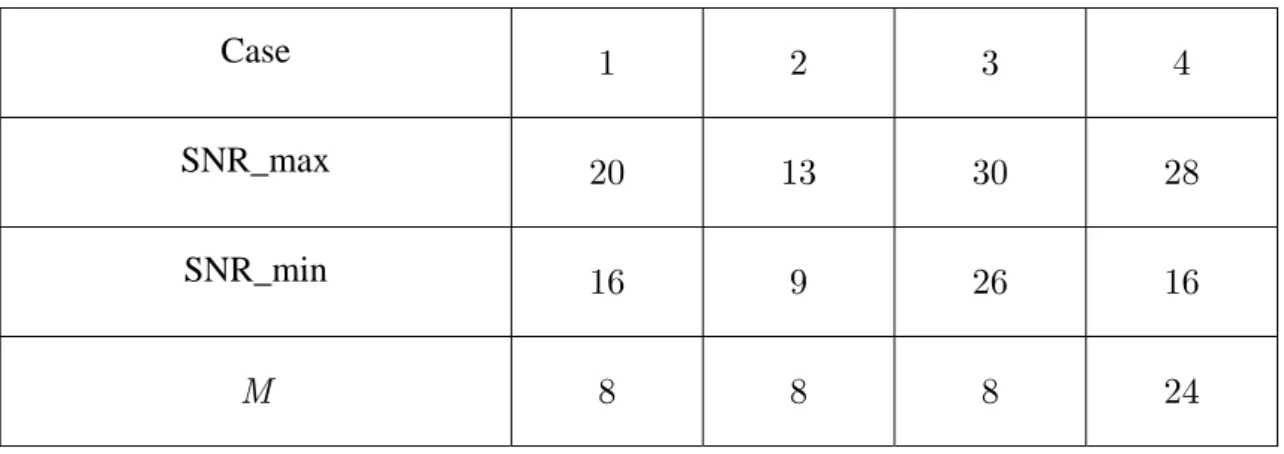
In this section, we compare the simulated results of the suboptimal cases and the proposed method mentioned in Section 3.1 and 3.2, respectively. The system deployment is the same as Section 3.1, which is a CDMA network with randomly generated spreading codes. In the first three cases, there are eight users deployed as in Fig. 3-3. The network deployment of the fourth case is given in Fig. 3-13. SNR_max and SNR_min in Table 3-1 represent the SNR level of the nearest and farthest users from the CC, respectively.
Table 3-1 SNR parameters of the four simulated cases
Case 1 2 3 4
SNR_max 20 13 30 28
SNR_min 16 9 26 16
Case 1:
The Joint AMC curve in Fig. 3-9 represents the performance of the proposed method, and the curve labeled as Suboptimal AMC (k) means that the MPR matrix is formed based on the parameters of mode k and the AMC is directly incorporated into MPR environment through the flow described in Fig. 3-2. It can be observed that the Joint AMC curve outperforms the other two suboptimal cases in the region p>0.45 (p: packet generating probability). The Joint AMC curve also attains the channel capacity of the MPR environment incorporated with AMC, which means that through Joint AMC-MAC design, the MPR capabilities of the physical layer can be fully exploited. In addition, it can be observed in Fig. 3-10 that although the Suboptimal AMC (1) curve outperforms Joint AMC in the delay performance, its throughput performance is worse than the Joint AMC curve.
It is observed that there exist some losses of the Joint AMC curve compared with the Suboptimal AMC (2) curve in the low traffic region (p<0.45) in Fig. 3-9. The reason of the low traffic loss is that in previous MPR works, it is assumed that all the selected n0 users are active to transmit packets, i.e. full load assumption. But this assumption is invalid in the low traffic region because the selected users might be idle. Thus in the proposed method, the invalid assumption causes that the interference levels are overestimated for all selected users, therefore CC assigns some weaker users Mode 1 to combat the overestimated interferences. In fact, those weak users could be assigned Mode 2 since the actual interference levels might be low in the low traffic region. Therefore, since users’ default modes are set to Mode 2 in Suboptimal AMC (2), it has more information bits in a packet and achieves a higher effective throughput than Joint AMC in the low traffic region.
0 0.1 0.2 0.3 0.4 0.5 0.6 0.7 0.8 0.9 1 0 0.5 1 1.5 2 2.5 3
Packet generating probability
Ef fe ct iv e t h ro u ghpu t ( P a c k e t/ S lot ) Joint AMC Suboptimal AMC(1) Suboptimal AMC(2)
Fig. 3-9 Throughput comparison between Joint AMC and suboptimal methods for Case 1 (SNR_max = 20 dB, SNR_min = 16 dB)
0 0.1 0.2 0.3 0.4 0.5 0.6 0.7 0.8 0.9 1 0 1 2 3 4 5 6 7 8 9 10
Packet generating probability
D e lay( S lo t/ P ack et ) Suboptimal AMC(2) Joint AMC Suboptimal AMC(1)
Case 2:
Simulation in Fig. 3-11 demonstrates a network in which all users’ SNR levels are very low such that the SINRs of the selected users are too low to activate the AMC mechanism. If the channel conditions are always poor, users will always be assigned Mode 1, i.e. AMC mechanism is not activated. This makes the proposed method acts almost the same as the Suboptimal AMC (1). To deal with the poor channel condition cases, some more robust modes, e.g. smaller constellation size or lower coding rate, may be considered to be added into the AMC mechanism to combat the bad environments. Besides, there still exist some losses in the low traffic area compared to the Suboptimal AMC (2) curve. This is because that although the SNR levels are low, the actual interferences from other users in the low traffic region are low as well.
0 0.1 0.2 0.3 0.4 0.5 0.6 0.7 0.8 0.9 1 0 0.5 1 1.5 2 2.5 3
Packet generating probability
E ff ect iv e t h ro u ghp ut ( P ack et /S lo t) Joint AMC Suboptimal AMC(1) Suboptimal AMC(2)
Fig. 3-11 Throughput comparison between Joint AMC and suboptimal methods of Case 2 (SNR_max = 13 dB, SNR_min = 9 dB)
Case 3:
This case simulates an environment in which all users’ SNR levels are high. It can be observed that the trends of Fig. 3-12 (Case 3) and Fig. 3-11 (Case 1) are almost the same, except that Case 3 corresponds to a better environment, which leads to a higher attainable channel capacity than others. In this kind of environment, larger constellation size modulation and higher coding rate transmission modes may be added to further increase the attainable channel capacity.
0 0.1 0.2 0.3 0.4 0.5 0.6 0.7 0.8 0.9 1 0 0.5 1 1.5 2 2.5 3
Packet generating probability
E ff e ct ive t h ro u g h p u t ( P acket /S lo t) Joint AMC Suboptimal AMC(1) Suboptimal AMC(2)
Fig. 3-12 Throughput comparison between Joint AMC and suboptimal methods for Case 3 (SNR_max = 30 dB, SNR_min = 26 dB)
Case 4:
This case demonstrates a network in which there are 24 users. It can be observed that the trend in Fig. 3-14 acts like a left-shifted version of the other cases. Since the number of users in this case is larger, the probability of the selected accessing users being idle is lower. Therefore the low traffic loss problem is less severe because the average waiting slots of users becomes longer when there are many users in the network. The longer the users wait the more probable they have packets to send as they are selected to access the channel; this mitigates the low traffic loss problem.
0 0.1 0.2 0.3 0.4 0.5 0.6 0.7 0.8 0.9 1 0 0.5 1 1.5 2 2.5 3
Packet generating probability
E ff e ct ive t h ro u g h p u t ( P acket /S lo t) Joint AMC Suboptimal AMC(1) Suboptimal AMC(2)
Fig. 3-14 Throughput comparison between Joint AMC and suboptimal methods for Case 4 (M = 24, SNR_max = 28 dB, SNR_min = 16 dB)
Case 5:
In typical AMC mechanisms, there are usually more than two modes for selection. The reason we only adopt two modes in this thesis is that using the two modes are quite enough for us to clarify the main idea of the proposed method. In this case, we add two more modes into the AMC mechanism as in Table 3-2 to characterize a more realistic system environment. In Fig. 3-15, it can be observed that attainable channel capacity is further increased, and the Joint AMC still outperforms other suboptimal methods. However, the low traffic loss becomes more severe since the coding rate of Mode 4 is higher.
Table 3-2 Adopted AMC modes in Case 5
Mode 1 2 3 4
Modulation BPSK QPSK 16-QAM 64-QAM
Coding rate 1/3 1/2 3/4 7/8 0 0.1 0.2 0.3 0.4 0.5 0.6 0.7 0.8 0.9 1 0 0.5 1 1.5 2 2.5 3
Packet generating probability
E ff ect ive t h ro u g h p u t ( P acket /S lo t) Joint AMC Suboptimal AMC (1) Suboptimal AMC (2) Suboptimal AMC (3) Suboptimal AMC (4)
Fig. 3-15 Throughput comparison between Joint AMC and suboptimal methods for Case 5
3.5 Summary
In this chapter, we give a detailed description of the proposed Joint AMC-MAC design. By the two simulations in Section 2.1, we showed that if the AMC mechanism is directly incorporated into MPR environments, the packet reception capabilities of the physical layer could not be fully exploited by the suboptimal flow depicted in Fig.
3-2. The Joint AMC-MAC algorithm uses a simple iterative procedure in Fig. 3-7 that tries every possible combination of user selection and modes to find the optimal user-mode combination, which can fully exploit the physical layer’s MPR capabilities. However, it can be observed that there exist some losses in the low traffic region in all simulated cases. This low traffic loss problem will be tackled in the next chapter, in which an enhanced version of the Joint AMC-MAC design will be introduced.
Chapter 4
Enhanced Joint AMC-MAC Design
In this chapter, we introduce the proposed Enhanced Joint AMC-MAC (Enhanced JAM) design. First, the proposed Probability Based Mode Tuning (PBMT) method is introduced. The Enhanced Joint AMC-MAC design is an extended version of the Joint AMC-MAC design discussed in Chapter 3. By exploiting the advantage of low complexity in MGPQ and throughput enhancement due to the joint optimization of user selection and modes assignment in the Joint AMC-MAC design, the Enhanced Joint AMC-MAC design further takes the traffic conditions into consideration during the iterative procedure. By the PBMT method, some users who originally assigned as Mode 1 may have chances to be reassigned as Mode 2 because the actual interference levels in the lower traffic region may be low. This method can be used to tackle the low traffic loss problem in Chapter 3. The simulation results show that the Enhanced Joint AMC-MAC design further improves the overall network throughput in the low traffic region. In Section 4.1 and 4.2, the proposed PBMT method and the Enhanced Joint AMC-MAC design are introduced. In Section 4.3, the proposed Enhanced Joint AMC-MAC design with MGPQ MAC protocol is summarized. Some numerical results are shown in Section 4.4. Section 4.5 summarizes this chapter.4.1 Proposed Probability Based Mode Tuning
Method
In the previous chapter, the Joint AMC-MAC algorithm is discussed. However, the simulation results show that there exist some throughput losses in the low traffic region. The low traffic loss results from the improper full load assumption which makes some of the selected users may be assigned robust but low coding rate mode to combat the overestimated interferences. To solve this problem, we can further utilize the packet generating probability and two properties of MGPQ protocol, the waiting slot counter and flag-bit. By these traffic related parameters, we can estimate the probability of the selected user being active, i.e. the interfering probability to other users. With this probability, we can obtain a new SINR level which is closer to the actual SINR level in the low traffic region. After the new SINRs being obtained, some users originally assigned as Mode 1 may have chances to be reassigned as Mode 2, which can compensate the low traffic loss problem in the previous chapter.
The modified SINR calculation (2.9) is modified as
( ) ( ) 0,AMC SINRi n U t i j j j i S S p N ≠ ′ = ⋅ +
∑
, (4.1) where ( ) , flag - bit on , flag - bit off 1 1 1 j j W p p ⎧⎪⎪⎪ = ⎨ ⎪ − − ⎪⎪⎩ (4.2)represents the probability of user j having packet to transmit, i.e. the probability of user j to interfere other users. p is the packet generating probability and Wj is the
(
)
( ) ( ) ( ) { } 2 3 BEP , 3 n i n j j j U i i G m N m U m Q P p G m P σ ∈ − ⎛ ⎞⎟ ⎜ ⎟ ⎜ ⎟ ⎜ ⎟ ⎜ ⎟ ⎜ ′ = ⎜ ⎟⎟ ⎜ ⎟⎟ ⎜ + ⎟ ⎜ ⎟ ⎜ ⎟ ⎜⎝∑
⎠ i . (4.3)With (4.3), we calculate (3.5) and (3.6) again and update the corresponding mode vector (i.e. the n0,AMC(U t( ))th row of CMAMC(U t( ))) to make sure that these users’ modes can match more to the actual traffic conditions..
4.2 Proposed Enhanced Joint AMC-MAC
Algorithm
In this section, the Enhanced Joint AMC-MAC algorithm is introduced. Fig. 4-1 depicts the Enhanced Joint AMC-MAC algorithm, which is a slightly modified version of the Joint AMC-MAC algorithm in Fig. 3-7. In the iterative procedure, we still use the full load assumption to obtain the optimal user-mode combination that maximizes the average throughput. Then, we append the PBMT algorithm after the iteration part to perform the mode reassignment procedure. The Enhanced Joint AMC-MAC not only compensates the low traffic loss discussed in the previous chapter, but also remains the advantage of the Joint AMC-MAC algorithm in the heavy traffic region since the estimation of users’ activity is more accurate. Some numerical results are shown in the next section.
Fig. 4-1 Enhanced Joint AMC-MAC algorithm
4.3 Proposed Enhanced Joint AMC-MAC
Design with MGPQ MAC Protocol
Central controller:
I. Put all users in the user set into the PREM group. II. Input: U(t)
temp_n0 = 1; temp_ η = 0; ηAMC(U t( ))= 0
while temp_n0 <= M
a) Calculate the SINR levels of the first temp_n0 users in U(t) by (2.9). b) Assign modes to the first temp_n0 users and record the associated
average throughput (temp_ η ) by the corresponding SINRs.
if temp_ η > ηAMC(U t( )) ( )
( )
AMC U t
( )
( )
0,AMC
n U t = temp_n0
Record the current user-mode combination
end if
temp_n0 = temp_n0 + 1
end while
III. Recalculate the selected n0,AMC(U t users’ SINR by (4.1) and update the ( )) corresponding transmission modes.
IV. Select first n0,AMC(U t users (by the order of PREM, ACTIVE, and then ( )) STANDBY group) in the user set and adopt the updated corresponding transmission modes to access the channel.
a) If the packet of a certain user is received successfully, then put the user to the tail of the ACTIVE (if the flag bit is on) or STANDBY group (if the flag-bit is off). Reset its count of waiting slots to zero.
b) If, for a certain user, the buffer is empty (no packet sent) or there is packet transmitted but not successfully received, then put the user back to the tail of the STANDBY or ACTIVE group in which the user originally stayed. Reset its count of waiting slots to zero.
V. Increase waiting slots of all users in the user set by one.
VI. Move those users with waiting slots equal to S to the PREM group. VII. Repeat steps II to VI.
4.4 Computer Simulations
In this section, we simulate the proposed Enhanced Joint AMC-MAC method and compare it with the proposed Joint AMC-MAC method and two suboptimal methods mentioned in Chapter 3. The network and the corresponding parameters are defined the same as in Chapter 3.
Case 1:
In the low traffic region of Fig. 4-2, it can be observed that the Enhanced Joint AMC curve behaves like the Suboptimal AMC (2) curve because the PBMT method reassigns some selected users as Mode 2. The mode reassignment procedure leads to the compensation of the low traffic loss in Fig. 3-9. Besides, in the heavy traffic region, the Enhanced Joint AMC curve overlaps the Joint AMC curve and attains the channel capacity, which means that the MPR capabilities can still be fully exploited by the Enhanced Joint AMC-MAC algorithm.
0 0.1 0.2 0.3 0.4 0.5 0.6 0.7 0.8 0.9 1 0 0.5 1 1.5 2 2.5 3
Packet generating probability
E ff ect ive t h rough put ( P acket /S lo t)
Enhanced Joint AMC Joint AMC
Suboptimal AMC(1) Suboptimal AMC(2)
Case 2:
As in Fig. 4-2, the Enhanced Joint AMC curve in Fig. 4-3 behaves the same as the Suboptimal AMC (2) curve at low traffic, and then overlaps the original Joint AMC curve with increasing traffic load. Since low traffic loss is not poor in such an environment, the improvement of the Enhanced Joint AMC over the Joint AMC in the low traffic region is not obvious too.
0 0.1 0.2 0.3 0.4 0.5 0.6 0.7 0.8 0.9 1 0 0.5 1 1.5 2 2.5 3
Packet generating probability
E ff e ct ive t h ro u g h p u t ( P acket /S lo t)
Enhanced Joint AMC Joint AMC
Suboptimal AMC(1) Suboptimal AMC(2)
Case 3:
Since the users’ SNRs are quite high in this case, the Enhanced JAM curve not only recovers the losses, but also slightly outperforms the Suboptimal AMC (2) curve, which is different from Case 1 in which the Enhanced JAM curve in Fig. 4-2 just acts the same as the Suboptimal AMC (2) curve in the low traffic region.
0 0.1 0.2 0.3 0.4 0.5 0.6 0.7 0.8 0.9 1 0 0.5 1 1.5 2 2.5 3
Packet generating probability
E ff e ct ive t h ro u g h p u t ( P acket /S lo t)
Enhanced Joint AMC Joint AMC
Suboptimal AMC(1) Suboptimal AMC(2)
Fig. 4-4 Throughput comparison among Enhanced JAM and other methods for Case 3
In the following Case 4 and Case 5, the trends of the curves are basically the same as in previous figures. The Enhanced JAM curve firstly recovers the losses in the low traffic region, and then overlaps with the original Joint AMC curve in the heavy traffic region.
Case 4: 0 0.1 0.2 0.3 0.4 0.5 0.6 0.7 0.8 0.9 1 0 0.5 1 1.5 2 2.5 3
Packet generating probability
E
ff
e
c
ti
v
e t
h
roughput
(P
ac
k
e
t/
S
lo
t)
Enhanced Joint AMCJoint AMC
Suboptimal AMC(1) Suboptimal AMC(2)
Fig. 4-5 Throughput comparison among Enhanced JAM and other methods for Case 4
Case 5: 0 0.1 0.2 0.3 0.4 0.5 0.6 0.7 0.8 0.9 1 0 0.5 1 1.5 2 2.5 3
Packet generating probability
E ff ect ive t h roughput ( P acket /S lo t)
Enhanced Joint AMC Joint AMC
Suboptimal AMC (1) Suboptimal AMC (2) Suboptimal AMC (3) Suboptimal AMC (4)
0 0.1 0.2 0.3 0.4 0.5 0.6 0.7 0.8 0.9 1 0 0.5 1 1.5 2 2.5 3
Packet generating probability
E ff ect ive t h roughput ( P acket /S lo t)
Enhanced Joint AMC Suboptimal AMC (3) Suboptimal AMC (4)
Fig. 4-7 Loss recovery of Enhanced Joint AMC compared with Suboptimal AMC (3) and (4) for Case 5
4.5 Summary
The proposed Enhanced JAM design is described in this chapter. This design incorporates the proposed PBMT method to recover the low traffic throughput loss of the original Joint AMC-MAC design. By appending the PBMT method at the tail of the JAM design, the Enhanced JAM provides opportunities to the selected users to be reassigned higher order transmission modes, which may be more proper to the actual traffic conditions. Computer simulations show that throughput performance can be improved by assigning users with more suitable modes instead of improper modes based on overestimated interferences.
Chapter 5
Conclusions and Future Works
In the beginning, this thesis introduces the basic idea of the AMC mechanism and reviews the MAC protocol with MPR capability called MGPQ, which is proposed with a simple flag-assisted mechanism and an efficient multi-priority user grouping strategy to achieve high performance in a wireless network with MPR capability. However, if the AMC mechanism is directly incorporated into the MPR environment, the MPR capability may not be fully utilized during the MAC scheduling process since the conventional MPR matrix cannot reflect the dynamic properties of the physical layer. Our design objective is to perform a cross layer design by jointly optimizing the user selection and the associated transmission modes, which makes the MPR capability fully exploited during the scheduling process. The proposed Joint AMC-MAC algorithm and Enhanced Joint AMC-MAC algorithm achieve the objective and improve the system throughput performance.
Aiming at fully exploiting the MPR capability of the AMC incorporated physical layer, this work tries to perform a cross layer design in a direction from MAC to PHY instead of a traditional way of PHY to MAC. By the proposed JAM design introduced in Chapter 3, we firstly find the optimal user-mode combination that attains the maximum average throughput from MAC layer, then reversely informs PHY of which
transmission mode should be adopted to fully utilize the MPR capability. In the JAM design, we use the full load assumption of traditional MPR works, which means that all the selected users are assumed to be active to transmit packets. This assumption may overestimate the interference levels of the selected users such that some users are assigned robust but low coding rate mode to combat the nonexistent interferences, i.e. the corresponding modes are underestimated. Therefore, the optimal user-mode combination obtained in the proposed method is inherently optimal for heavy traffic conditions, where the full load assumption is more likely to be valid. In the low traffic region, the improper full load assumption may cause some throughput loss due to users’ underestimated transmission modes.
In Chapter 4, the PBMT method of the Enhanced JAM algorithm is proposed to recover the low traffic throughput loss by providing the selected users with opportunities to be reassigned more proper modes to the associated traffic conditions. There are three steps in the PBMT. We firstly estimate every selected user’s probability of being active, i.e. the probability of interfering other selected users. Secondly, we recalculate the selected users’ SINRs by multiplying the interferences with the estimated active probabilities. The third step is to check whether the updated SINRs are qualified to be reassigned higher order modes. It is demonstrated that the proposed method outperforms other suboptimal methods, in which the AMC mechanism is directly incorporated into MPR environments. The simulations in Sections 3.4 and 4.4 show the superiority of the proposed methods.
If AMC mechanism is directly incorporated into MPR environments, then the users’ SINRs for mode assignment depend on the number of selected users, i.e. n0. However, the information about n0 needs to be extracted from the MPR matrices, which are constructed based on users’ parameters of transmission modes. Since the