行政院國家科學委員會專題研究計畫 期末報告
行動合作網通之無線訊號與訊息處理技術研究--子計畫
二:合作型感知通訊之機會式傳輸技術
計 畫 類 別 : 整合型
計 畫 編 號 : NSC 101-2219-E-009-019-
執 行 期 間 : 101 年 05 月 01 日至 102 年 04 月 30 日
執 行 單 位 : 國立交通大學電子工程學系及電子研究所
計 畫 主 持 人 : 馮智豪
計畫參與人員: 此計畫無其他參與人員
報 告 附 件 : 出席國際會議研究心得報告及發表論文
公 開 資 訊 : 本計畫可公開查詢
中 華 民 國 102 年 07 月 30 日
中 文 摘 要 : 在多天線干擾通道傳輸多仰賴精確的通道資訊,但因往往缺
乏精準的通道資訊,穩健傳輸設計也與誤匹配模型的保守程
度息息相關。以往的誤匹配模型不是過於保守(確定模
型),就是被其分布函數及其參數所誤(隨機模型)。為了
解決此問題,本研究計畫中提出使用確定型結構性誤匹配模
型(SMM)使用在多天線干擾通道穩健傳輸設計。不同於以往的
誤匹配模型,SMM 善加利用多天線干擾通道之統計相關矩陣
中隱含的稀疏特性。在感知無線環境中的前置編碼設計,在
本研究計畫中,不論是理論分析或是實驗數據,均顯示使用
SMM 時,較多的傳輸功率被分配給干擾通道中的稀疏元素
上,因此,相較於傳統範數球誤匹配模型,在通訊鏈有較佳
的通訊品質。
中文關鍵詞: 干擾迴避,感知無線電,多天線系統,前置編碼,非完美通
道
英 文 摘 要 : Transmission over MIMO interference channel often
relies on the use of robust precoder due to a lack of
accurate channel state information, with performance
often depending on the conservativeness of the
mismatch model. Previously proposed mismatch models
either have been deemed too conservative
(deterministic models) or are prone to error due to
inaccuracy in the pdf and corresponding parameters
(stochastic models). A deterministic mismatch model,
called \emph{structural mismatch model}, or SMM, is
proposed herein in attempt to alleviate these
problems. Different from all previously
deterministic models, the SMM exploits the inherent
sparse characteristics of MIMO interference channel
in the form of the statistical correlation matrix.
In the context of precoder design for cognitive radio
systems, it is shown analytically and by simulation
that the SMM enables the transmitter to allocate more
transmission power to the sparse elements of the
interfering (SU-Tx to PU) link so that performance in
the communicating (SU-Tx to SU-Rx) link is enhanced
compared to conventional norm ball mismatch model
(NBMM).
英文關鍵詞: Interference avoidance, cognitive radio, MIMO,
precoder, imperfect channels
Structural Mismatch Model for Robust
Transmission in MIMO-CR Network
Principal Investigator: Carrson C. Fung Project Number: NSC-101-2219-E-009-019 Effective Date: May 1, 2012 to Apr. 30, 2013
Abstract
Transmission over MIMO interference channel often relies on the use of robust precoder due to a lack of accurate channel state information, with performance often depending on the conservativeness of the mismatch model. Previously proposed mismatch models either have been deemed too conser-vative (deterministic models) or are prone to error due to inaccuracy in the pdf and corresponding parameters (stochastic models). A deterministic mismatch model, called structural mismatch model, or SMM, is proposed herein in attempt to alleviate these problems. Different from all previously deterministic models, the SMM exploits the inherent sparse characteristics of MIMO interference channel in the form of the statistical correlation matrix. In the context of precoder design for cognitive radio systems, it is shown analytically and by simulation that the SMM enables the transmitter to allocate more transmission power to the sparse elements of the interfering (SU-Tx to PU) link so that performance in the communicating (SU-Tx to SU-Rx) link is enhanced compared to conventional norm ball mismatch model (NBMM).
Keywords
Interference avoidance, cognitive radio, MIMO, precoder, imperfect channels
I. INTRODUCTION
Multiple antennas have recently been exploited to enable efficient transmission over interference channel in the presence of inaccurate channel state information (CSI). This inaccuracy exists in the channel state information (CSI) of both the communicating and interfering link due to lack of estimation accuracy and handshaking. The MIMO interference channel (MIMO-IC) model can be applied to model a cognitive radio system when secondary users (SUs) and primary users (PUs) are allowed to transmit simultaneously but the transmission of the SUs are oblivious to the PUs. This is accomplished by constraining the transmit power at the SU transmitter (SU-Tx) toward the PUs so that the interference toward the PUs is unnoticeable. In this case, the communicating link in the MIMO-IC models the channel between the SU-Tx and SU receiver (SU-Rx) while interfering link
models the channel between the SU-Tx and PU. However, performance of such system is hindered by inaccurate CSI between the SU-Tx and the PU, as well as SU-Tx and SU-Rx, but the channel estimation error in the former will be greater thus more detrimental to system performance. Although optimal channel learning time has been derived to maximize the accuracy of the CSI, the accuracy will undoubtedly be limited by the use of blind channel estimators.
Stochastic and deterministic mismatch models to model mismatch between the actual and estimated CSI have been incorporated in transmitter [1], [3]–[6], [8], [9] and transceiver [2], [7] designs to guard against performance loss caused by channel estimation noise. The stochastic model attempts to model the mismatch in the form of confidence level. In [1], the mismatch terms associated with the communicating and interfering links are assumed to be independent and identically complex Gaussian distributed and the transmit power toward the PUs are bounded using a probabilistic constraint. In [2], only the 1st and 2nd order statistics about the mismatch terms are assumed known a priori and that the mean of the transmit power toward the PUs are bounded. However, using the stochastic model requires the knowledge of the distribution function, or the first and/or second-order statistics of function of the channel estimate. The optimality of the design will be affected if the assumed pdf and/or corresponding parameters are incorrect or inaccurately estimated.
In contrast, the deterministic mismatch, or worst-case performance, model assumes a priori knowl-edge about the maximum error bound and model the error using norm ball. This shall be known hereafter as norm ball mismatch model or NBMM, which can be generalized to an ellipsoid by assuming a priori knowledge about the directionality of the mismatch. In the context of cognitive radio, the deterministic mismatch model has been applied to a wide array of designs, from single SU and PU robust precoder design [3], [4], multiple SUs and PUs robust precoder design [5], [6], robust precoder design for multicast signal transmission [8], [9], to robust transceiver design [2], [7]. Unfortunately, the error bound, i.e. radius of the norm ball, that is assumed to bound the energy of the mismatch is often chosen arbitrarily, thus affecting optimality of the design. By assuming the channel coefficients and estimation noise are jointly Gaussian, a closed-form equation for the error bound was given in [10] in which estimation of the Gaussian parameters are required.
Although the above (conventional) stochastic and deterministic models can account for the channel estimation error in the communicating and interfering links, they are not designed specifically to take advantage of the potential offered by the MIMO-IC. A deterministic mismatch model called the structural mismatch model, or SMM, is proposed herein for precoder design at the SU-Tx. The proposed model allows the secondary transmitter to utilize higher transmit power without violating the interference constraint placed at the PUs, resulting in enhanced performance for the SUs. This is achievable because the additional transmit power have been “absorbed”, or allocated, to the sparse elements in the interfering channel. The design problem aims to maximize the minimum receive
SNR with an average or instantaneous interference constraint of the PU. Even though the single SU scenario is considered in this project, the proposed model does not preclude the inclusion of multiple SUs, in which problem formulation and methodology similar to the ones considered in [6] can be used.
The SMM deals with channel uncertainty by exploiting the structural property, which translates into sparsity, of the statistical correlation matrix of the channel between the SU-Tx and the PUs. The structural property refers to the diagonal elements of the spatial correlation matrix which always equal 1. The amount of sparsity which can be exploited for precoder design in cognitive radio systems to attain higher performance compared to the use of the NBMM will be shown analytically to be equal to the number of transmit antennas at the SU-Tx times the number of receive antennas at the PU, i.e. nTnP.
The system model and design metric for the precoder design are given in Sec. II, followed by a complete exposition of the SMM and formulation of the precoder design problem using it in Sec. III. Simulation results are presented in Sec. IV and the paper is concluded in Sec. V.
Notations: Upper (lower) bold face letters indicate matrices (column vectors). SuperscriptH denotes Hermitian,T denotes transposition. [A]ij denotes the (i, j)th element of A.E[·] stands for statistical expectation of the entity inside the square bracket. A≻ 0 and A ≽ 0 mean A is a positive definite and positive semidefinite matrix, respectively. IN denotes an N× N identity matrix. Denote 1M×N and 1M as an M× N matrix and M × 1 vector, respectively, containing 1 in all of their entries. ⊗ and◦ denote the Kronecker and Hadamard product, respectively. vec(·) is the vectorization operator.
tr(A) denotes the trace of the matrix A. ∥·∥2 and ∥·∥F denote ℓ2 and Frobenius norm, respectively.
ℜ(·) denotes the real part of the argument. R(A) denotes the column space of A. Sn denotes a set of n× n Hermitian symmetric matrices. λmax(A) denotes the maximum eigenvalue of matrix A.
R+/R− denotes a set of positive/negative real number. |S| denotes the cardinality of the set S
II. SYSTEMMODEL ANDDESIGNMETRIC A. System Model
Herein a single SU transmitter and receiver equipped with multiple antenna is considered. All PUs have nP antennas while the SU-Tx and SU-Rx have nT and nR antennas, respectively. The channel between SU-Tx and SU-Rx, the so-called communicating link, is denoted as H ∈CnR×nT and the
channel between SU-Tx and the kth PU, the so-called interfering link, is denoted as Gk ∈CnP×nT. Orthogonal space-time code (OSTBC) is used to encode the data signal vector s ∈ CB×1 at the SU-Tx containing 4-QAM modulated symbol with equal probability and equal power, i.e. |si|2= 1. Therefore, the received signal matrix at the SU-Rx is Y = HFC+N∈CnR×T, where F∈CnT×B is
with T denoting the number of symbols encoded in time and B denoting the number of data streams during T , and N∈CnR×T is the noise matrix containing zero-mean, independent Gaussian distributed
samples with known variance σ2n. It is assumed that the noise is uncorrelated with the data signal. Finally, a maximum likelihood (ML) decoder is employed at the SU-Rx to recover an estimate of the data signalbs ∈ CB×1.
B. Design Metric
Given that OSTBC encoding and ML decoding are used, the reliability of the SU link is evaluated by the symbol error rate (SER), which is inversely proportional to the receive SNR [10]
SNR (∆H) = T σ2 n ∥HF∥2 F = T σ2 n (H + ∆b H ) F 2 F, (1)
where bH and ∆H denote the estimate and error (or mismatch) matrix of H, respectively, such that
H = bH + ∆H. σn2 is the noise power. The proposed robust precoder is formulated by maximizing the minimum of SNR (∆H), denoted as SNRmin, given that the transmit power and interference
constraints are not violated. SNRmin is obtained by finding the “worst case” ∆H, denoted as ∆wstH , where δwstH , vec(∆wstH ) ∈ H, so that SNRmin = SNR
( ∆wstH ) with HE , { δH| δHHBδH ≤ 1 } .
B ≻ 0 defines the shape and direction of an ellipsoid and it is used to bound ∆H. Without a a priori knowledge of ∆H, it is assumed that B = ε12
HInTnR, implying that the uncertainty model
degenerates back to a norm ball, and it is bounded as ∥∆H∥2F ≤ ε2H. That is, ∆H ∈ HN BM M , {
∆H ∥∆H∥2F ≤ ε2H }
, where HN BM M shall be referred to as the NBMM for H and it shall be used hereafter to bound the norm of ∆H.
Since Gkwill likely be estimated blindly as there is no handshaking between the SU and PUs, two uncertainty models are proposed hereafter to deal with the expected large degree of estimation error in Gk. For improved aesthetic, without loss of generality, the subscript k in Gk and its associated mismatch matrix shall be ignored in the derivation in the following sections, and will only appear in the final problem formulation.
In the next section, the SMM will be introduced and it will be shown how the interference constraint is formulated using it. The constraint will be combined with the design metric described in this section to form the complete formulation of the precoder design. Comparison will be made with the design using the NBMM for the mismatch between G and its estimate.
III. STRUCTURALMISMATCHMODEL (SMM)ANDPRECODERDESIGN
The Kronecker channel model [15] shall be adopted so that G = R1/2G,PGwRT /2G,T ∈ CnP×nT.
RG,T ∈CnT×nT and RG,P ∈CnP×nP are spatial covariance matrix at the SU-Tx and PU, respec-tively. RG , E
[
channel matrix G. The entries of Gw ∈ CnP×nT are identical and independent complex Gaussian distributed with zero mean and unit variance. Hence, the average interference power toward the PU can be written as E[∥GF∥2 F ] =E[ (FT ⊗ InP ) vec(G) 22 ] = tr(((FFH)T ⊗ InP ) RG ) .
Let RG= bRG+ ∆R, where bRGdenotes the estimate of RG, and ∆R is its corresponding mismatch matrix. In the present scheme, the error power is upper bounded such that ∆R∈ URs, with
SMM : Us R, { ∆R| ∥∆R∥F ≤ εR, ∆HR = ∆R, [∆R]ii= 0,∀i }
expressing the proposed SMM, since [RG]ii= 1,∀i due to the use of the Kronecker model.
Notice thatURs is different from the traditional NBMM defined asURb ,{∆R| ∥∆R∥F ≤ εR, ∆HR = ∆R }1
, where the structural property of RG, i.e. [RG]ii= 1,∀i, is not exploited.
Ignoring σT2
n in (1) and let ∆H ∈ H and ∆R∈ U
s
R, the precoder F can be computed by solving max F ∆minH∈H (H + ∆b H ) F 2 F s.t. tr(((FFH)T ⊗ InP ) ( b RG+ ∆R )) ≤ Qth, ∆R∈ URs, tr ( FFH)≤ Pth, (2)
where Pth and Qth are the maximum transmit power of the SU-Tx brought about by F and the interference constraint threshold of the PU, respectively. Denote Q , FFH and eQP , QT ⊗ InP,
(2) can be rewritten as max Q ∆minH∈H tr (( b H + ∆H ) Q ( b H + ∆H )) s.t. tr ( e QP ( b RG+ ∆R )) ≤ Qth, ∆R∈ URs, tr (Q)≤ Pth, rank(Q) = B, eQP = QT ⊗ InP. (3)
The use of URs allows the precoder to maintain high link reliability for a continuum of all possible channel covariance mismatches given by URs instead of providing such performance for only a fixed channel covariance matrix. However, the existence of infinite number of constraints also makes finding the solution impossible. Fortunately, the problem can be bypassed by finding an upper bound for
tr ( e QP ( b RG+ ∆R ))
of which ∆R ∈ URs. The result of this bound using URb and URs is stated
1
The only difference between the NBMM for H,HN BM M, andURb, is the symmetry condition for ∆R. This is of course
needed because the latter mismatch model is applied to the mismatch matrix associated with a Hermitian matrix. Since the symmetry condition does not affect the performance of the model, hence,H and URb shall both be referred to as NBMM
in Theorem 1, which is called the Power Allocation exploiting Sparsity Theorem-SMM, or PAST-SMM. This name is used because as the theorem will show, more transmit power can be used when
∆R∈ URs is employed (compared to URb) as part of the precoder design for cognitive radio systems because more transmit power can be allocated to the interfering channel without exceeding Qth.
Theorem 1: Power Allocation exploiting Sparsity Theorem-SMM (PAST-SMM): An upper bound for tr ( e QP ( b RG+ ∆R )) using (i) the NBMM defined as URb is
max ∆R∈URb tr ( e QP ( b RG+ ∆R )) = tr ( e QPRbG ) + εR eQP F , (4) and using
(ii) the SMM defined as URs is max ∆R∈URs tr ( e QP ( b RG+ ∆R )) = tr ( e QPRbG ) + εR ¯InTnP ◦ eQP F, (5) where ¯InTnP , 1nTnP×nTnP − InTnP.
The amount of sparsity in the SMM that can be exploited by precoder design for performance improvement equals nTnP.
Proof: The proof of the PAST-SMM is shown in Appendix A.
The result of the PAST-SMM allows for reduction in symbol error rate compared to the use of the NBMM in [6]. Numerical result corroborating this claim is shown in Sec. IV.
Therefore, employing semidefinite relaxation [11], in which the rank constraint (3) is removed so that (3) becomes max Q ∆minH∈H tr (( b H + ∆H ) Q ( b H + ∆H )) s.t. tr ( e QPRbG ) + εR ¯InTnP ◦ eQP F ≤ Qth, tr (Q)≤ Pth, eQP = QT ⊗ InP. (6)
After the optimal solution for (6) is obtained, the randomization procedure proposed in [8], [14] can be used to find a precoder matrix, denoted as Fopt, which is of rank B. Specifically, randA method is used, in which Fopt = UQΛ
1/2
Q E, from Q = UQΛQUHQ, where [E]ij = ejθij and θij are independent identical uniform distributed on [0, 2π). There is no guarantee, however, that Fopt will be the same as the solution of (3), but (6) is easier to solve. Two methods are used hereafter to solve the minimization problem stated in (6).
1) Lower Bound (LB) Method: Instead of directly solving for the solution of the minimization problem min ∆H∈H tr (( b H + ∆H ) Q ( b H + ∆H )) ,
it is possible to find its lower bound and substitute it into (6). The following theorem will ease the derivation of the lower bound [3].
Theorem 2: Receive signal is lower bounded by
tr (( b H + ∆H ) Q ( b H + ∆H )) ≥ tr (QA) , where A, bHHH +b ( ε2H − 2εH bH F )
InT. Equality holds iff
∆H =−kH, rank ( b H )
= rank (∆H) = rank (F) = 1, and R(HbT
)
=R(∆TH)=R (F) .
Proof: The proof is given in Appendix B.
However, the first condition is difficult to achieve as H is supposedly unknown. The second and third condition cannot be attained without severely diminishing the design freedom of the precoder. Even if the first condition is satisfied, the solution obtained will still be suboptimal.
Therefore, including PU index k, (6) can be rewritten as
LB + SMM : max Q tr(QA) s.t. tr ( e QPRbG,k ) + εR ¯InTnP ◦ eQP F ≤ Qth,∀k tr (Q)≤ Pth, eQP = QT ⊗ InP, (7) which is a convex SDP.
2) S-Procedure (SP) Method: By hypograph equivalence [13], (6) can be rewritten as
max Q,γ γ s.t. tr(( bH + ∆H)Q( bH + ∆H)H)≥ γ, ∀∆H ∈ H, tr ( e QPRbG ) + εR ¯InTnP ◦ eQP F ≤ Qth, tr (Q)≤ Pth, eQP = QT ⊗ InP. (8)
Define bh , vec( bH), δH , vec (∆H), and eQR , QT ⊗ InR. Using the fact that tr
(
XAXH)=
xH(AT ⊗ Im )
be expressed as tr (( b H + ∆H ) Q ( b H + ∆H )H) = ( bh + δH )H( QT ⊗ InR) (bh + δH ) = δHHQeRδH + 2ℜ ( bhHQe RδH ) + bhHQeRbh.
The first constraint, which contains infinite number of constraints, can be replaced by a linear matrix inequality (LMI) via S-lemma [13].
Theorem 3: (S-Lemma): For Ai ∈ Sn , and ci ∈ R, where i ∈ {0, 1}, and b ∈ Cn. Suppose Slater condition holds, i.e., ∃˜x ∈ Cn such that ˜xHA1x + c˜ 1 > 0, then the following two statement
are equivalent: (i) xHA0x + 2ℜ
(
bHx)+ c0 ≥ 0, ∀xHA1x + c1≥ 0.
(ii) ∃α ≥ 0 such that
A0− αA1 b
bH c
0− αc1
≽ 0.
Let x = δH, A0 = eQR, A1 =−B, b = eQRbh, c0 = bhHQeRbh − γ, and c1 = 1. Including the PU
index k, (8) is equivalent to the convex SDP
SP + SMM : max Q,γ,α≥0γ s.t. QeR+ αB QeRbh bhHQe R bhHQeRbh − α − γ ≽ 0, tr ( e QPRbG,k ) + εR ¯InTnP ◦ eQP F ≤ Qth,∀k tr (Q)≤ Pth, e QR= QT ⊗ InR, eQP = Q T ⊗ I nP. (9)
It will be shown in Sec. IV that precoders designed using the proposed SMM, via the lower bound method (7) and the SP method (9), outperform over those designed using the NBMM defined asURb. As alluded earlier, this is because higher transmit power can be used without violating the interference constraint due to the existence of the sparse elements in ¯InTnP ◦ eQP
F induced by U s R. IV. SIMULATIONS
All simulations employ 4-QAM modulation. One PU is considered hereafter. Simulation results using the SMM are generated using 2× 2 Alamouti OSTBC, with B = 2, T = 2, nT = 4, and nR = 2. Without loss of generality, nP is assumed to be 1. The channel matrix between the
SU-Tx and PU degenerates to a vector G = gT = gTwRT /2G,T ∈ C1×nT. The average interference becomes E [ ∥GF∥2 F ] = tr(FFHRG,T )
. The antennas are aligned in an uniform linear array with half wavelength antenna spacing. The spatial correlation matrix RG,T is generated according to [15], where the mean angle of departure (AoD) is 65◦, and the angular spread (AS) is 25◦. The entries of
H are independent and identically complex Gaussian distributed, with zero mean and unit variance.
Uncertainty level εH and εR have been normalized to have values in the interval [0, 1]. The transmit power threshold Pth is set to 10 and interference threshold Qth is set to 0.1.
To establish the efficacy of the proposed SMM based precoder design, the robust precoders designed from (7) and (9) are also compared with one designed using the norm ball constraint as stated inURb. Hence, four different cases are compared: LB method with norm ball constraint, LB method with the SMM (see (7)), S-procedure (SP) method with norm ball constraint, and SP method with the SMM (see (9)).
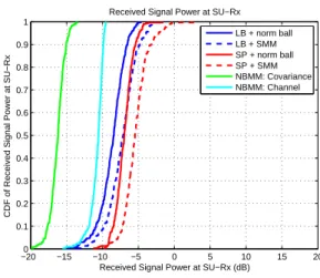
Fig. 1 shows the CDF curve of the receive signal power∥HF∥2. It is clear that the proposed SMM design enables the SU-Rx to receive higher signal power than the NBMM based methods by about 1.5 dB on average. It is shown in the figure that using the SP method with the SMM outperforms the channel and covariance constraints based designs proposed in [6] by about 5 and 10 dB, respectively, when the instantaneous interference threshold in [6] is Ith = 0.01 or -20 dB. This is again due to the existence of ¯InTnP ◦ eQP
F in (9) which allows for more transmit power to be used without exceeding Qth. This is verified in Fig. 2 which shows higher transmit power tr(Q) are consistently achieved using the SP method with structural constraint than all other methods. This increase in receive SNR translates directly into gain in SER as shown in Fig. 3 where the SP and LB methods with the SMM are able to outperform their NBMM counterparts by 1 and 2 dB, respectively, at SER = 10−2. −200 −15 −10 −5 0 5 10 15 20 0.1 0.2 0.3 0.4 0.5 0.6 0.7 0.8 0.9 1
Received Signal Power at SU−Rx (dB)
CDF of Received Signal Power at SU−Rx
Received Signal Power at SU−Rx LB + norm ball LB + SMM SP + norm ball SP + SMM NBMM: Covariance NBMM: Channel
Fig. 1. CDF curve of receive signal power∥HF∥2 at the SU-Rx. εH= 0.1 and εR= 0.3. NBMM herein stands for the
−300 −25 −20 −15 −10 −5 0 5 10 0.1 0.2 0.3 0.4 0.5 0.6 0.7 0.8 0.9 1
Transmit Power at SU−Tx (dB)
CDF of Transmit Power at SU−Tx
Transmit Power at SU−Tx LB + norm ball LB + SMM SP + norm ball SP + SMM NBMM: Covariance NBMM: Channel
Fig. 2. CDF curve of transmit power tr(Q). NBMM herein stands for the method proposed in [6].
0 5 10 15 20 10−5 10−4 10−3 10−2 10−1 100 SNR SER LB + norm ball LB + SMM SP + norm ball SP + SMM NBMM: Covariance NBMM: Channel
Fig. 3. SER versus SNR performance comparison. εH= 0.1 and εR= 0.3. NBMM herein stands for the method proposed
in [6].
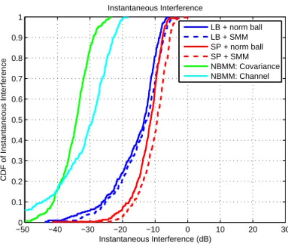
Figures 4 and 5 show the instantaneous interference power toward the PU and the average inter-ference power toward the PU from the SU-Tx, respectively. The instantaneous interinter-ference power is defined as∥GF∥2F, and the average interference power is defined asE
[ ∥GF∥2 F ] = tr(FFHRG,T ) . From the figures, it is clear that the PU experiences a lower level of interference from the SU-Tx when the NBMM is used. This is understandable as the higher interference power experienced at the PU in the SMM based systems translates into higher receive power at the SU-Rx. Even though higher average interference power is experienced by the PU when the proposed model is used, the average interference constraint is not violated, i.e. P r(average instantaneous power ≤ −10dB) ≈ 1, as the average interference power constraint is used as part of the proposed design. However, since the instantaneous interference power is not used as a constraint in both the NBMM and SMM
based designs, hence, it is possible for both methods to experience instantaneous interference power exceeding −20 dB (Ith= 0.01). −500 −40 −30 −20 −10 0 10 20 30 0.1 0.2 0.3 0.4 0.5 0.6 0.7 0.8 0.9 1 Instantaneous Interference (dB) CDF of Instantaneous Interference Instantaneous Interference LB + norm ball LB + SMM SP + norm ball SP + SMM NBMM: Covariance NBMM: Channel
Fig. 4. CDF curve of instantaneous interference power∥GF∥F toward PU. εH = 0.1 and εR = 0.3. NBMM herein
stands for the method proposed in [6].
−500 −40 −30 −20 −10 0 10 20 0.1 0.2 0.3 0.4 0.5 0.6 0.7 0.8 0.9 1 Average Interference (dB) CDF of Average Interference Average Interference LB + norm ball LB + SMM SP + norm ball SP + SMM NBMM: Covariance NBMM: Channel
Fig. 5. CDF curve of the average interference power toward the PU, in terms of tr(FFHR G,T
)
. εH = 0.1 and εR= 0.3.
NBMM herein stands for the method proposed in [6].
V. CONCLUSION
A mismatch model called the structural mismatch model, or SMM, is proposed for robust interfer-ence channel transmission when CSI in the communicating and interfering links is inaccurate. The results were presented in the context of a cognitive radio system in which the SU-Tx is allowed to transmit simultaneously with the PU, but without causing noticeable interference at the PUs. It has been shown that precoder design using the SMM can outperform its NBMM counterpart by
2 dB in terms of transmit power and SER, by successfully trading off the interference power, but without violating the average interference power constraint. Analysis has been included to highlight the deficiency of the lower bound method. It has been shown analytically in the PAST-SMM that the performance gain of the SMM comes from allocation of the transmit power to the sparse elements in the interfering link, where this sparsity is brought forth by exploiting the structural property of the statistical correlation matrix of the channel in the SMM. It was also proven that the amount of sparsity available to be exploited by the SMM for precoder design equals nTnP.
APPENDIX A
PAST-SMM
(i) Since eQP is Hermitian symmetric, according to the Cauchy-Schwarz inequality, tr ( e QP∆R ) ≤ eQP
F ∥∆R∥F. Equality holds iff ∆R and eQP are linear dependent, i.e., ∆R = k eQP. In addition, since∥∆R∥F ≤ εR, maximum of tr
( e QP∆R ) occurs at k = εR/ eQP F. Therefore, max∆R∈Ub Rtr ( e QP∆R ) = εR eQP
F. Substituting this into the left-hand side of (4) would equal to the right-hand side of (4).
(ii) Denote Au and Aℓ as the strictly upper and lower triangular portion of matrix A, respectively. Also denote Ad as diagonal portion of A. Note that
tr ( e QP∆R ) = tr ( e QuP∆ℓR ) + tr ( e QℓP∆uR ) + tr ( e QdP∆dR ) = tr ( e QuP∆ℓR ) + tr ( e QℓP∆uR ) . (10) tr ( e QdP∆dR )
vanishes because [∆R]ii= 0. Due to Hermitian symmetry of eQP, eQuP = ( eQℓP)H, thus tr ( e QuP∆ℓR ) + tr ( e QℓP∆uR ) = tr (( e QℓP )H ∆ℓR ) + tr (( e QuP )H ∆uR ) . (11) In URs, ∆R is also Hermitian symmetric, i.e., ∆uR =
(
∆ℓR)H, implies ∥∆uR∥2F = ∆ℓR 2F =
∥∆R∥2F/2≤ ε2R/2. Applying the Cauchy-Schwarz inequality, tr (( e QℓP )H ∆ℓR ) ≤ eQℓP F ∆ℓ R F. (12)
Equality holds iff ∆ℓR and eQℓP are linear dependent, i.e., ∆ℓR = kℓQeℓP. Furthermore, since ∆ℓR ≤εR/
√
2, the maximum occurs at kℓ= εR /(√ 2 eQℓP F ) and tr (( e QℓP )H ∆ℓR ) ≤ εR eQℓP F / √ 2. Since eQℓP 2 F + eQuP 2 F = ¯InTnP ◦ eQP 2 F and eQℓP F = eQuP F, it is clear that eQℓP F = ¯InTnP ◦ eQP F / √ 2 so that tr (( e QℓP )H ∆ℓR ) ≤ εR ¯InTnP ◦ eQP F 2 . (13)
Similarly, tr (( e QuP )H ∆uR ) ≤ εR ¯InTnP ◦ eQP F 2 . (14)
Substituting (13) and (14) into (10), it can be concluded that
max ∆R∈URs tr ( e QP∆R ) = εR ¯InTnP ◦ eQP F. (15)
Substituting (15) into (5), the second part of the proof is complete.
Comparing (4) and (5) in Theorem 1, and interpreting the result by incorporating these equations into (2), the existence of ¯InTnP ◦ Q removes all the diagonal terms in Q, which allows the corresponding
elements of Q more room to increase when the worst-case SNR is maximized without causing any constraint violation. This can be interpreted as allowing more transmit power to be used as they are “absorbed” by, or allocated to, the zeros in ¯InTnP ◦ Q . Hence, the amount of power allocated to
the interfering link equals nTnP. Note that this result is similar to the water-filling solution in which the coefficients of Q serve as the bottom of the subchannel of the effective channel GF, which is similar to the role the inverse eigenmode coefficients played in the water-filling solution. Hence, (15) suggests that the use of the SMM allows the removal of some of the coefficients in Q, resulting in higher transmit power utilization.
APPENDIXB LINEARBOUNDTHEOREM
Corollary 1: For A∈ Cm×n and B ∈Cn×p, then ∥AB∥F ≤ ∥A∥F∥B∥F. Equality is attained iff rank(A) = rank(B) = 1 and R(AT) =R(B).
Proof: Since ∥AB∥2 F = ∑ i,j a′Hi bj 2 ≤∑ i ∑ j a′i 22∥bj∥22=∥A∥2F ∥B∥2F ,
where (a′i)H = [ai1· · · ain] is the ith row of matrix A and bj is jth column of B. From the Cauchy-Schwarz inequality, equality is attained when a′i = kbj∀i, j, implying that a′i and bj are linear dependent∀i, j. In other words, rank(A) = rank(B) = 1 and R(AT) =R(B).
Lemma 1 (Reverse triangle inequality): For A, B ∈ Cn×m, ∥A + B∥F ≥ ∥A∥F − ∥B∥F . Equality holds if A = kB, where k∈R−.
Proof: ∥A + B∥2 F =∥A∥ 2 F + 2ℜ { tr(BHA)}+∥B∥2F ≥ ∥A∥F2 − 2 tr(BHA) +∥B∥2F ≥ ∥A∥2 F − 2 ∥A∥F∥B∥F +∥B∥ 2 F = (∥A∥F − ∥B∥F) 2
The first inequality is true because − |z| ≤ ℜ(z), ∀z ∈C and the second inequality is true due to the Cauchy-Schwarz inequality. In addition, for the equality condition of both these inequalities to be true, it requires that A = kB and k∈R−.
Using the reverse triangular inequality, it follows that (H + ∆b H ) F 2 F = bHF + ∆HF 2 F ≥ ( bHF F − ∥∆HF∥F )2 , (16)
where the equality will hold iff ∆H = −kH and k ∈ R+. Using Corollary 1 and the fact that
B = ε12
HInTnR,
∥∆HF∥F ≤ ∥∆H∥F∥F∥F ≤ εH∥F∥F, (17) where the first equality will hold by Corollary 1 iff rank (∆H) = rank (F) = 1 and R
(
∆TH)=
R (F). Substituting (17) into (16) and expanding, (16) becomes( bHF
F − ∥∆HF∥F )2 ≥ bHF 2 F+ ε2H∥F∥2F − 2εH bHF F∥F∥F Noting that bHF F ≤ bH
F ∥F∥F, then the above becomes bHF 2 F + ε 2 H∥F∥ 2 F − 2εH bHF F∥F∥F ≥ bHF 2 F + ( ε2H − 2εH bH F ) ∥F∥2 F = tr ( FFH ( b HHH +b ( ε2H − 2εH bH F ) InT )) . (18)
It should be noted the equality conditions in (16), (17), and (18) will hold iff
∆H =−kH, rank ( b H )
= rank (∆H) = rank (F) = 1, and R(HbT
)
=R(∆TH)=R (F) .
REFERENCES
[1] G. Zheng, S. Ma, K.-K. Wong, and T.-S. Ng, “Robust beamforming in cognitive radio,” IEEE Trans. on Wireless Communication, vol. 9(2), pp. 570-576, Feb. 2010.
[2] E.A. Gharavol, Y.C. Liang, and K. Mouthaan,“Robust linear tranceiver design in MIMO ad hoc cognitive radio networks with imperfect channel state information,” IEEE Trans. on Wirelss Commnication, vol. 10(5), pp. 1488-1457, May 2011.
[3] M.H. Islam, Y.-C. Liang and R. Zhang, “Robust precoding for orthogonal space-time block coded MIMO cognitive radio networks,” Proc. of the Workshop on Signal Processing Advances in Wireless Communications, pp. 86-90, Jun. 2009.
[4] L. Zhang, Y.-C. Liang, Y. Xin, and H. V. Poor, “Robust cognitive beamforming with partial channel state information,” IEEE Trans. on Wireless Communications, vol. 8(8), pp. 4143-4153, Feb. 2009.
[5] E.A. Gharavol, Y.-C. Liang, and K. Mouthaan, “Robust downlink beamforming in multiuser MISO cognitive radio networks with imperfect channel-state information,” IEEE Trans. on Vehicular Technology, vol. 59(6), pp. 2852-2860, Jul. 2010.
[6] G. Zheng, K.-K. Wong, and B. Ottersten, “Robust cognitive beamforming with bounded channel uncertainties,” IEEE Trans. on Signal Processing, vol. 57(12), pp. 4871-4881, Dec. 2009.
[7] H. Du, T. Ratnarajah, M. Pesavento, and C.B. Papadias, “Joint transceiver beamforming in MIMO cognitive radio network via second-order cone programming,” IEEE Trans. on Signal Processing, vol.60(2), pp. 781-792, Feb. 2012. [8] K.T. Phan et al., “Spectrum sharing in wireless networks via QoS-aware secondary multicast beamforming,” IEEE
Trans. on Signal Processing, vol. 57(6), pp.2323-2335, June 2009.
[9] Y. Huang et al., “Robust multicast beamforming for spectrum sharing-based cognitive radios,” IEEE Trans. on Signal Processing, vol. 60(1), pp.527-533, Jan. 2012.
[10] A. Pascual-Iserte, D. P. Palomar, A. I. Perez-Neira, and M. A. Lagunas, “A robust maximin approach for MIMO communications with imperfect channel state information based on convex optimization,” IEEE Trans. Signal Processing, vol. 54, no. 1, pp. 346-360, Jan. 2006.
[11] Z.Q. Luo et al., ”Semidefinite relaxation of quadratic optimization problems,” IEEE Signal Process Magazine, May 2010.
[12] C.-Y. Chang and C. C. Fung, “Robust interference channel transmissionusing sparsity enhanced mismatch model,” Statistical Signal Processing Workshop (SSP), pp. 836-839, Aug. 2012.
[13] S. Boyd and L. Vandenberghe, Convex optimization, Cambridge University Press, 2004.
[14] N.D. Sidiropoulos, T.N. Davidson, and Z.-Q. Luo, “Transmit beamforming for physical layer multicasting,” IEEE Trans. Signal Processing, vol. 54(6), pp. 2239-2251, Jun. 2006.
1
國科會補助專題研究計畫項下出席國際學術會議心得報告
日期: 101 年 09 月 01 日一、參加會議經過
SSP is a biannual all-poster workshop. However, there are totally 6 plenary talks provided
in this SSP workshop. The first one is “Xampling at the Rate of Innovation: Correlations,
Nonlinearities, and Bounds” by Prof. Yonina Eldar. “Xampling” is the term related to
sampling at a rate which is lower than Nyquist rate. Then, prof. Robert Ghris introduced
the topic of “Topology Signal Processing”. These two talks are the 2 plenary talks for the
first day. For the second day, Prof. Robert Nowak provided a talk entitle as “Adaptive
Sensing and Active Learning.” Machine learning is a hot topic recently, and the active
learning method can dramatically reduce the number of labeled training examples needed
to design good classifiers. In the afternoon, prof. Persi Diaconis from Stanford University,
who is a former magician, introduced the talk as “Adding Numbers and Determinental
Point Processes.”On the last day, Prof. Yoram Bresler introduced the topic of “The
invention of Compressive Sensing and Recent Results,” which is especially applied to
spectrum blind sampling and image compression. Finally, Prof. Randy Moses shared his
results entitled as “Radar Signal Processing.” can dramatically reduce the number of
labeled training examples needed to design good classifiers.
I am able to present my work on the last day.
二、與會心得
計畫編號
NSC 101-2219-E-009-019
計畫名稱
合作型感知通訊之機會式傳輸技術
出國人員
姓名
張傑堯
服務機構
及職稱
Dept. of Electronics Engineering,
NCTU, Ph. D. Candidate
會議時間
Aug. 5~8, 2012
會議地點
Ann Arbor, USA.
會議名稱
(中文) IEEE 統計訊號處理會義
(英文)
IEEE Statistical Signal Processing Workshop
發表論文
題目
(中文) 在干擾通道上使用 SEMM 方法之穩健傳輸
(英文)
Robust Interference Channel Transmission Using Sparsity Enhanced
Mismatch Model
2
![Fig. 3. SER versus SNR performance comparison. ε H = 0.1 and ε R = 0.3. NBMM herein stands for the method proposed in [6].](https://thumb-ap.123doks.com/thumbv2/9libinfo/8714879.200192/12.892.296.585.482.720/fig-versus-performance-comparison-nbmm-stands-method-proposed.webp)