Proceedings of the 2004 IEEE
International Conference on Control Applications Taipei, Taiwan, September 2-4,2004
Supervised Nonlinear Control of Hybrid System
with Application to HVAC System
Chin-I Huang', YrMing Chan', and Li-Chen F U ' . ~ Department of Electrical Engineering
Depamnent of Computer Science and Information Engineering National Tai- University, Taipei, Taiwan, R.O.C.
E-mail: [email protected]
AbstracC In this note, we have proposed B systematic approach for the hybrid system controller designs. We integrate discrete event system (DES) and continuous variable dynamic system ( C W S ) theories, while taking both sizes of operation logics as well as the system performanee into account, to propose a novel approach for the hybrid system controller design. In order to verify the performance of the proposed controllers, we perform a number of computer simulations of B real-world W A C hybrid system.
I. INTRODUCTION
Hybrid system is simply a group of time-driven and event- driven components working together to provide multi-object functionalities. The ultimate system dynamics is the resulting of interactions of CVDS and DES. Traditional controller design methodology cannot directly be applied here because hybrid system cannot he modeled hy the set of differential
primary modeling tool in this note. Assuming there are N distinct Components each equipped with a sensor and/or actuator. The automaton model of the ilk component is a six- tuple.
G, =
{
X ,A,
6
r,,
x,,~ 1,m ]where Xr is the finite discrete state set, Z, is the discrete event set, Jr : X , xZ,
+
X, is the transition function which indicates the transition relationship, x , , ~ is the initial state and Xr,m is the marked state set of automaton Gr , Whichgenerate language Lj and mark language Lr,m
(1)
L, = ( t
z:
I
6 ( x , , o , t ) ! )La,, = {l E L,
l J ( i " J )
%}
(2)
where Z: is the set of traces or event sequence form from the equations [7]. Control of hybrid system usually involved
multi-layer controller architecture. The operation logics event set
zr
and S ( x i , e ) ! means there exist an event e such controlh
the upper layer is to control the o d o f f sequences ofhybrid system that guarantee the controlled hybrid system will complete tasks. The servomechanism wntrol in the lower layer is to control the performance such that will satisfy some set of constrains.
Form level of abstractions, we can imagine the hybrid system evolves as a DES. That is, the system evolutes as between several discrete state (heating, cooling) causing hy the occurrence of discrete events. The supmisory controller that feedback event sequence, can do control of the onloff event sequence of hybrid system. When the system operates in some operation mode, the continuous system trajectory (temperature) can be formulated hy some set of differential equations. The servo controller that feedback the system trajectory can do wntrol of the servomechanism performance of hybrid system.
In
fact,DES
and CVDS components may affect each other and causing the ultimate hybrid system overly highly complex and difficult to be controlled. So a systematic methodology for the controllers design for hybrid system control is important for the wming hybrid system era and it's also a challenge tasks for their inherent complex nature.II.
SYSTEMMODELINGFor the investigation and study logical level behavior of hybrid system, we choose finite state automata [2, 71 as
nux
that bring state from x, to some other state x,'
.
Language L, is the set of all traces that automaton Gr can perform, which can demonstrate the possible behaviors of theirk
equipment. When we model all the individual equipment into automaton, we need to composite them to obtain the overall system automaton model. Composite of two automata is to capture their joint behavior retain each individual behaviors. The formal d e f ~ t i o n of composite operation as Eq.(3). The overall automaton modelof
hybrid system can be obtained by consecutively composite all of individual automaton. That is G =11
G,,
Mmich genetate language L and mark language Lm.
&&se
While system operates well, the ultimate system behavior can he thought as switching system, which can he formulated as
where 0, is the operation indicator of the k" operation mode, it is a discrete mapping from system state x tu discrete Values 0 or 1. It Cm also interpreter as the 0CC-g of discrete event when system state reaches to some saturation
region.
mere
we there are one operation mode e ELC
name these states are suprema1 infermediateat any instantaneous time point and the system is modeled as
the collecting of k subsystems each modeled by differential
0)
Removing these suprema1 intermediate stafesin
f/ andequation
f,
.
(c) The supremal controllable sublanguage K f C = LNtc
Ill. CONTROLLERS DESIGN Procedures tu calculate the in6mal prefix-closed controllable superlanguage tiJc listed as below.
(a) Labeling the illegal state
f
in automaton G such thatZ=
2 name theseillegal states are infimal intermediate states.
(71) lnclnding these infimal intermediate states and all the directed traces attached on it to automaton H and obtain the autom&on f f L C ,
(c) The infimal prefic-closed controllable superlanguage
K ~ c = LHw ,
controllable superlanguage ti". Procedures tu calculate the supremal controllable sublanguage K T C listed as below.
(a) Labeling the state x in H such that 6 ( x , e ) = f , f o r any
States.
obtain automaton H f C
.
3. I Supervisory Controller Design
Supervisory conbol of DES is based on the assumptions that some of the uncontrolled system behavior are illegal and we hope tu restrict, by control, it f" occurring. That
is we
hope system behavior become fromL
tu the relative small oneti,
the system specification. When we model the overall system into automaton G,
the procedures of supervisory controller design listed as below.(a) According to the problem we concerned, labeling each of the illegal state
f
E X in automaton G.
=
'
2 for E xn and e(6) Removing these illegal states and all the directed traces attached
on
it. obtain automaton HCase
In
such case, we need tu test the observability of system(c) System specification K = L,,
(d)
If
= Zwo =4 ,
see case 1.(e)
If
Zuc t4,
Zuo =4 ,
see case 2.fl If
Zwe =4,
Z,,, it4 ,
see case 3. (g)If
1, I4,
Zuo =4 ,
see case 4.Language K is said tu be controllable with respect tu L and Z u c j if
and observable
with
respect toP
andZ,
,
if fur all I Ea
and fur all U E Zo
,
Eq. ( 5 ) hold Where P :+
Z: is the projection from traces tu observable traces.I z , n L c K
( 5 )[tu
e
K ] A [ t u E L ]a
P - ' [ P ( t ) ] u n t =4
( 6 )Case 1
In such case,
K
is contrullahle and observable respect tu L,
Z, and P,
Zc , Design supervisor S = G x H,
The feasible event set'function of controlled DES S / G becomesr , , , ( ~ , , x ~ ) = r ( ~ ~ ) n r ( x , , ) .
Same as the control actionS ( t ) is encoded into the transition fmdion of H
.
That isL(HxC)=L(H)nL(G)
= + I C ) Case 2
specification
K ,
due tu the affect of unobservable event. If K is observable, unobservable event nu effect, we need tu build the observer of automaton H,
H.
Observer automatonH can be obtain from H after grouping the state of H
.
Here, observer means the state transition of H depends on the occurrence of observable event of H
.
Fur any event sequence t = t'u,(U
E Zo) that observe so far, the event sequences that H may generates arestate of
fi
is $ ( & , I ) and thepossible states of H is the setL, =
{
sI
s = P-1 ( I f ) LT}X
= [ xI
s E L , J " (X",J)!}(8)
(9) we call $ ( f 0 , t ) is a "super" state because it can he represented as the set of states of H
.
f?
can be obtained from H if we grouping the state of H , Gmuping of statesmeans if there exist an unobservable event sequence between states in H then all these states were on same group and belong tu a particular super state
of
H , Control action S { t )in such case becomes
S ( f ) =
U
m ( x H ) (10)xn s6(i0 ,,I
Eq. (10) means the control action after supervisor observe event sequence t is depends on feasible event set of observer
? ( $ ( i 0 , t ) ) . The feasible event set of observer at some super
In such case, we need tu test the controllabiW of system specification K due tu the uncontrollable event effect.
If
K is wntrollable, uncontrollable event nu effect, we follow thestate, called
$(io,t),
equals to the union of all the feasible event set of at x H for any xH containsin
the 'uper Statesupervisor design approach discussed in case 1. If K is $(;.t)
\ I ,
uncontrollable, we h o w there exist
nu
supervisor tu achievecontrollable sublanguage K T c and infimal prefix-closed
men
system specification is unobservable, we lmow there exist nu supervisor can achieve our control goals due tu goals' Instead we can calculate thecontrol policy contradiction problem. Instead, we can calculate the maximum observable sublanguage
K"
,
infimal prefix-closed observable superlanguage K i 0 . we h o w that K is unobservable due to there exist some states inH ,
which have mutual exclusive control policy and which are belongs to same super state in H.
Because we hope to obtain the maximum observable sublanguage fromK
,
we need to remove these contradiction states from H to ensure the language generated thereafter is observable. Procedures to calculate the maximum observable snblanrmage KfMO listed as below.Q, =
n,
(x) (11)C O k = 1
i
- kEq. (1 1) means the effect of system state is contributed by the of k subsystems, each of them model by a differential
equation f , ( x , u , , 0 , ) witb a discrete event effect embed in it. Where is the indicator of k" operation mode, which can be determinate by function
n,
, n:x+{O,l]
is a- Y
(a) Labeling each of the control policy contradiction state of
/bi Removing these conlrol D O ~ ~ C V contradiction states in H
discrete mapping from continuous system state to discrete value 0 or 1, used to represent the occurrence of model- chaneed event. Where value 1 indicates system states reach at U .
I/ Y 1 . I
ami obtain automaton H" or over some saturation region and 0 otherwise. Furthermore,
we assume there is only one operation mode at any instantaneous time mint.
(c) The marimum observable sublanguage K i m = L,,,.
.
Procedures to calculate the infimal prefi-closed obsemable superlanguage K'O listed m below.
(d) Labeling states x E X , \ X,, not in the state space of H
ami which are causing control policy contradiction due to disabling ofsome eventfrom occurring.
(e) Include it and all the directed path connected with it to
U andobtain HI"
The intimal prefx-closed observable superlanguage K ' O = L";"
3.2 Servo Controller Design
In general, embed in a hybrid system are DES and
CVDS.
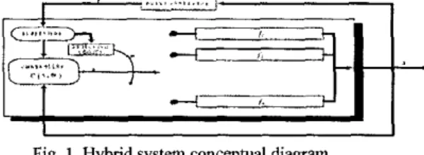
DES usually reflects the state transition or switching of operation modes in hybrid system. State transition in hybrid system causing by the occurring of discrete event at discrete time point, event such as turn o d o f f of a equipment, detect button pressed or the generate of interrupt signal when system state reach to some particular saturation region. Different operation model has its own dynamics also and the CVDS of hybrid system can be thought as switching between these several dynamics different subsystems as illustrate in Figure 1. Design a hybrid system controller to stable the system isa
challenge tasks because the ultimate system dynamics is complex and contains event driven componentI I
Fig. 1. Hybrid system conceptual diagram
Assume there are k different operation modes within a hybrid system and the operation mode indicator, denoted by 0,. is determinate by the DES embed in it. We model the hybrid system as the switching between a set of equations. That is
Stability issue [M.S. Branicky] is important of hybrid system and om goal is to design a controller C(x,O.) to stable the overall system. Let us define a Lyapunov function candidate V = i x ' , the time variation is
P = x x = x
i,
( X , U * , O , )1
(12) while system operate at some operation model, say modej
,
rewrite Eq. (12) asr'
=xr,
(x,c(
x, 0,))design the correspondence j" mode control algorithm C(x,O,) such that satisfy
v
< - y x ' , the j' mode control algorithm then obtain asfrom Lyapunov theory, we h o w system will stable in mode j if we apply the control as Eq. (14). Continuing design control algorithm for the total k possible operation mode C(x,O,),C(x,O,),..-,C(x,O,) and cboosethe control apply to hybrid system as the from
(13)
C(x,@,) = -yx(f;l(x,.)) (14)
C(x.0) =CC(x,0,)0, (15) it is a variable structure controller. From Eq. (15), we h o w
V will decade asymptotically for arbitrary switching between any two operation mode and the overall system will state in the sense of Lyapunov.
Tv.
APPLICATION TO W A C SYSTEMWe follows the controllers design method proposed in the preceded section apply to a real word W A C (heating, ventilating and air conditioning system) hybrid system. The main propose of W A C system is to provide the people working inside building with conditioned air so that they will have a comfortable and safe work environment. Conditioned air means that air is clean and odor-fiee, and the temperature, humidity, and movement of air are within certain comfortable ranges. The schematic diagram of the conventional W A C system illustrated as Fig. 2. Where a group of components
working together to move heat to where is wanted @eating) or to remove heat from where it is not wanted (cooling) and
and theprecedence-forbidden states of G, are (RAFOFF
...
CHVON...
) put is where it is un-subjectionable (ventilation). 1..
SAFOFF...CHVON.....~
Fig. 2. Schematic diagram of W A C System 4.1 Supervisory Controller Design
(a) Model each of the individual components into automaron model. The automalon model of component those perform heating functionality show os Fig. 3 and cooling functionalify show QS Fig. 4. where doshed
circle in each automaton model is ifs initial stale. We assume the sensor reading be the uncontrollable evenf. that is Z,, = (Above-SP, Below-SP}
.
@) Composite each individual automaton model to system. Heating subsystem-
Automaton model of heating subsystem G,, is composite by 7 individual automaton models. That is,
G,=G,,IIG,IIG,IIC,IIG,,IIG,,IIG,
number of states in G,, is 296. Cooling Subsystem-
The cooling subsystem G, is composite by 10 individual automaton models. That is,
Gc=GwIIGwIIG, IIG~IIGcm I I ~ ~ ~ ~ I I G ~ I I ~ ~ ~ ~ I I G ~ ~ I I ~ ~ number of states in
c,
is 1280. Due to space consideration,we will not sketch out heating and cooling subsystem automaton model.
(c) Labeling each of the forbidden states
Heafihg subsystem
Mer composite operation the state space of heating
subsystem is 'I-pairs as ( x ~ ~ , x ~ ~ , x ~ , x ~ , x ~ . , x ~ ~ , x ~ ~ ) ,
thepressurezforbidden' states o f G,, are (.,.,*,.,HVOFF,HWP~N,.)
andprecedencezfo~bidden' states of G,, are
(RAFOFF.-,.,*,HVON,-,*)
(e. SAFOF'F,*,-HVON,.,.)
...
CHWPOFf...CPON..
)(.
...
CWPOFF,CPON,.) Removing the illegal states.Heaffng subsystem
Let automaton H,, he the automaton, which obtain from after removing forbidden states of G,, , Number of states
inH, is118.
Cooling subsystem
Let automaton Hc be the automaton, which obtain from removing forbidden states of G,
.
Number of states in Hc is163
System specification.
Now, we must to elect two event sequences t,, t L (H,,
)
andtc E L(H,) he OUT reference control event sequence illustrated for hating and cooling subsystem. The overall W A C system reference control event sequence show
as
in Fie. C~Fig. 3 Automaton model of heating components
0
._.~._ .
-...
...
....
&-
...
...
...
~..~..
...
j..~..
..~."
.~.
...
...
...
~..
T S T Cwhere symbol means don't care, same as for a q possible state.
State in Gc is 10-pairs as ( x R U , x s U ; . x r s . ~ , x ~ ~ . , x ~ ~ ~ ~ , x ~ ~ , . ~ x ~ ~ ~ , x ~ ~ , x ~ ~ ) thepressureYorbidden states
o f
G, arej".~."
...
Cooling subsystem C H " C O Y'.a
...
~.O
...
...
...
1....
ClNOFF.CHWP0N...
C n w I C W P (....
CHVO rr.......
CuoN.. ) (....
COVOFF.CwPON,.,.) (....
COvOFF..,C~ON..)'
cause system undpr Ygh prerrure.*
Indicate emuol RAF or S A E inappropriately.0
-
.
...
...
...
C P L D
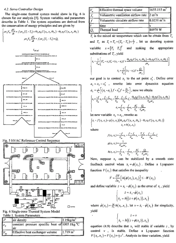
4.2. Servo Controller Design
The single-zone thermal system model show in Fig. 6 is chosen for our analysis [ 5 ] . System variables and parameters describe in Table I . Tbe system equations are derived from the conservation of energy principles and are given by
- ~ ) + @ ~ ~ ~ c ( = , , ~ ~ , @ ~ ) ~ Q ~ ~ ~ C ( ~ , , ~ ~ . @ ~ )
2=
/pep (1; -1,) + QLv,
f, f
Fig. 5 HVAC Referen :ontrol Sequence
Effective thermal space volume 1655.115
m3
volumetric ventilation aimow rate 2m3/s
Volumetric circulate airflow rate 8.0231 m'ls
Fig. 6 Sigle-zone Thermal System Model
11
V,,
]Effective heat exchanger volume 11.719 m3~ ~
f ]time s
0. Ihermalload 184970 W
,=I. I I I1
I;
is the mixed air temperature which can be obtain fromT.
andT,
as I ; = T , + ( T , - T , ) x $ , let us denoting system variable x = [ T , T , r and making the appropriate substihdions ofI;,
yieldOUT goal is to control x2 to the set point x;
.
Defmemor
e, = x i - x i
,
rewrite into error dynamics equatione2 = $[(x, - e , ) /
-
xi/+
%]
,
now we obtainNow, suppose x2 can be stabilized by a smooth state feedback control when x, =#(x,)
.
Defme a Lyapunov function V ( x 2 ) that satisfies the inequalityand define variable z = x, - # ( x l ) as the error of x,
,
yieldi
= X1-&)I
X, = h ( ( z + # ( x , ) ) , x , )where $ ( x 2 ) = g h ( x , , x 2 ) , let u = i , - c j ( x ? ) for simplicity, yield
z = v
= h ( ( z
+
#(x,))
, x 2 )equation (4.9) describe that xi will stable if variable z , by control v
,
is stable. Defme a Lyapunov function,“d.:;lan om&,# 2 ,
,
,
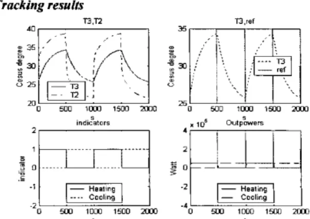
... . ... ... . ... ... .... Tracking resulfs T3.n 73 re,Fig. 9. Switching of operation mode simulation.
VI.
CONCLUSIONIn
this paper, we integrate DES switching effect into HVAC dynamics and model a W A C control as a hybrid system control problem. We prove the stability of the ultimated hyhird system through Lyapunov stability analysis. The simulations have been sdopted to verify the feasibility not only of the individual operation mode, hut also the switching during two operation modes.REFERENCES
[I] P. I. Ramadge and W. M. Wonham, “The control of discrete event systems,” Proc. IEEE, vol. 17, no. 1, pp. 81-98, January 1989.
[Z] M. Sampath, R, Sengupta, S . Lafortune, K. Shamhideen, and D. Teneketzis, “Failure diagnosis wingdiscrete went models,” IEEE Trans. Control Systems Tech., vol. 4, no. 2, pp. 105-124, March 1996.
[3] Michael S. Branicky, “Multiple Lyapunov functions and other analysis tools for switched and hybrid systems,”
IEEE Trans. Automatic Control, vol. 43,
no.
4, April 1998.[4] Michael D. Lemmon, Kevin X. He, and Ivan Markovsky, “Supervisory hybrid systems,” IEEE Control System
Magazine, vol. 19, pp. 42-55, August 1999.
[ 5 ]
J.
Teeter and M. Y. Chow, “Application of functional link neural network to HVAC thermal dynamic system identification,” IEEE Trans. Industrial Elecnonics, vol.45,
no.
I , pp. 170-176,
February 1998.[6] B. Argiiello-Serrano and Miguel Velez-Reyes, “Nonlinear control of a heating, ventilating, and air conditioning system with thermal load estimation,” IEEE Tram.
ConfrolSystems Tech., vol. 7, no. I, January 1995. [7] C. G. Cassandras and
S.
Lafortune, Introduction toDiscrete Event Svstems. Kulwer Academic Publishers,
1999.
[8] M. Vidyasagar, Nonlinear Systems Analysis, Prentice Hall, 1993.