1588 IEEE TRANSACTIONS ON COMMUNICATIONS, VOL. 41, NO. 11, NOVEMBER 1993
High-speed Decoder of Reed-Solomon Codes
Shyue-Win Wei and Che-Ho WeiAbstract-A high speed decoding algorithm using a modified step-by-step method for t-error-correcting Reed-Solomon codes is introduced. Based on this algorithm, a sequential decoder and a vector decoder are then proposed. These two decoders can be constructed by four basic modules: the syndrome calculation module, the comparison module, the decision module, and the shift-control module. These decoders can be applied for both binary and nonbinary data transmissions working at high data rate. Because of the simplicity in structure and circuit realization, a decoder employing this algorithm can be easily implemented in a monolithic chip by the VLSI technology.
1. INTRODUCTION
HE Reed-Solomon (RS) codes are a special subclass of
T
the nonbinary BCH codes in which the symbol field and the locator field are the same. The RS codes that applied for binary data transmission over GF(2") can be implemented by simply treating successive m-bit blocks as 2"-ary symbols, and will outperform binary codes with the same rate and block length at low output error rates [l]. In general, two primary approaches, algebraic decoding method and transform method, can be employed to decode the RS codes. The transform method is a fast decoding method for large t-error-correcting RS codes. However, since this method needs to perform the transform operation, it is comparable to the standard algebraic method in algorithm and implementation for small t RS codes Another algebraic decoding algorithm for BCH codes, known as step-by-step decoding method, was presented by Massey [9] in 1965. The basic principle of the step- by-step decoding algorithm for nonbinary t-error-correcting BCH codes can be summarized as follows: 1) calculate the syndrome values 2) change the syndrome values, using an iteration method, to make the weight of error pattern exactly equal to t. 3) temporarily add in order all the q-
1 nonzero elements of GF(q) to the decoding symbol of the received word with testing to determine whether the weight of the error pattern has been reduced. If the weight of error [21-[81.Recently, a new step-by-step method for decoding double- error-correcting binary BCH code has been presented by the authors [lo]. In this paper, by modifying the conventional step- by-step algorithm, a high-speed decoding algorithm for RS codes is presented in Section 111. A sequential decoder based on the decoding algorithm is then proposed in Section IV. The decoder comprises a syndrome calculation module, a comparison module, a decision module, and a shift-control module. Furthermore, in Section V, a vector structure of line speed decoder for short n small t RS codes is presented. The operation clock rate of the new vector decoder is equal to the line rate, and one complete received word can be decoded within only n clock cycles.
11. REED-SOLOMON CODES
A t-error-correcting Reed-Solomon code with symbols from the Galois field GF(2") has the following parameters
P I
-PI:
Block length = n = 2" - 1.
Number of parity-check symbols = n - k = 2t. Minimum distance = dmin = 2t
+
1.Let a be a primitive element in GF(2m). The generator polynomial g(z) of a t-error-correcting RS code of length 2" - 1 is the polynomial of degree n - k with coefficients from GF(2m), and has Q , a 2 , .
. . ,
a2t as its roots. Let k ( z ) be the information polynomial, then the encoded codeword c(z) in systematic form can be obtained as ~ ( z ) = k(z)z"-'+
Mod{ k(z)z"-'/g(z)} where Mod{ k ( z ) s n - ' / g ( z ) } indi- cates the remainder polynomial of k(z)z"-' divided by g(z).
Hereinafter, all the codewords are assumed to be in systematic form.
Let e ( s ) be a received error pattern, then the received word is given by
r(s) = c(z)
+
e(.)= To
+
T I 2+
T 2 2 2+
. . .
+
r,-/Jn--l. (1)pattern is reduced to t - 1, then both the error location and the corresponding error value are found. 4) shift r ( z )
one symbol and repeat step 3). The difference between the step-by-step method and the standard algebraic method is
The coefficients of c(z), e(z), and r ( z ) are elements from GF(2m). The syndrome values of a received word can be obtained from
. . -
-
that the step-by-step method decodes every potential error location and value directly instead of searching the roots of error location polynomial and evaluating the error values. Paper approved by M. Shahshahani, the Editor for Coding and Applications of the IEEE Communications Society. Manuscript received August 6, 1989; revised March 18, 1992.
The authors are with the Institute of Electronics and Center for Telecom- munications Research, National Chiao Tung University, Hsin Chu, Taiwan, Republic of China.
s,P
= r(ai) = e ( a i ) E GF(am) i = 1 , 2 ,. . .
, 2 t . (2) The syndrome values can also be written ast
s,P=cyx;
l = l , 2 , . . . , 2 t (3) j=1where X j is the error location of the jth error symbol and Yi
is the corresponding error value. Therefore, the decoding task IEEE Log Number 9211382.
IEEE TRANSACTIONS ON COMMUNICATIONS, VOL. 41, NO. 11, NOVEMBER 1993 1589 is, given the syndrome values, to find the error locators and
the error values.
111. DECODING ALGORITHM
A modified step-by-step decoding algorithm is presented in the following. The algorithm corrects the errors directly in terms of the differences between the original syndrome values and the temporarily changed syndrome values. This idea is based on the fact that various weights of error patterns can be distinguished from one another in terms of the relations among syndrome values. The relations among syndrome values of the
RS codes can be found by using property 5 of [9], theorem 9.9
of [ll], or theorem 7.2.2 of [3]. These theorems state the fact that if the number of errors is j - 1 or less then the syndrome matrix N! is singular, and if the number of errors is j then the syndrome matrix Nj” is nonsingular, where
Since the step-by-step decoding method involves changing received symbols one at a time with testing to determine whether the weight of the error pattern has been reduced, the weight of error pattern in the decoder may be
t
+
1 or less. Therefore, the variation in the weight of the error pattern from 0 up to t+
1 should be discriminated by the decoder if the step-by-step method is employed. That is, various weights ofthe error patterns should be distinguished from one another. The weight of error pattern can be determined from the values of det(N!) ( j = 1 , 2 , . +
.
,
t
+
l ) , where det(N:) indicatesthe determinant of the syndrome matrix
Nj”.
However, the calculation of det( Nt+,) requires the syndrome value S,ot+,which can not be obtained from the received words for a
t-
error-correcting RS code. Thus, it is necessary to define a
modified syndrome matrix de@:+,) as
det(
x+,)
= det($+’)+
S:,+’ det(N?) (4)where the submatrix N t is the cofactor of element S,ot+, in
matrix N;+,. Clearly, det(N,+,) is composed of S;, j
5
2t. Conse uently, if t - 1 or less errors have occurred, then det(N,+,) = 0 because det(N;+,) = d e t ( N f ) = 0; ift
+
1 errors have occurred and det(Nf) = 0, then det(N,+,)#
0 because det(N;+,)#
0. Since we are only concerned whether the values of det(N!), j = l , 2 , . - . , t , and det(X;+,) are equal to zero, the results can be expressed byt
+
1 binary decision bits, hj” ( j = 1,2,.
.
,
t+
l ) , defined by4
-8
-4
hy = 1 if det(Nj”) = 0 j = 1 , 2 , . . . , t (Sa)
h:+l = 1 if det(X:+l) = 0 (5b)
and, a
( t
+
1)-tuple decision vector H o is then defined asH 0 = (h?, h;, * * .
,
h:+’).
(6)4
Suppose the det ( N f ) for j = 1 , 2 , .
.
,
t
and ( N , + , ) can be found, the decision vector of a general t-error-correcting RS code can be determined as follows:If there is no error, then H o E $0 =
{
(1”+’)} wherelt+l indicates
t
+
1 consecutively identical tuple of “1” For example, vector(
i3) = (I, 1 , l ) .If there is one error, then H o E 41 = ((0, It)}.
If there are p errors, 2
5
p<
t,
thenH o
EdP
= { ( X P - ’ ,If there are
t
errors, then H o E $+ = { ( X t - ’ , 0 , X ) } .If there are
t
+
1 errors, then H o E 4t+l = {(Xt-’, 0, X),Where,
4J
(05
j5
t
+
1) is a set of all possibly happened decision vectors that j errors have occurred.From the above rules, we find that a) for the error patterns whose weights are t or less, the various weights of error patterns can be distinguished from one another b) the error pattern with weight
t
+
1 can be distinguished from the error pattern whose weight is t - 1 or less. Thus, the number of errors can be correctly determined in terms of the pattern of decision vector if and only if the weight of error pattern ist
or less. It will be shown later that the above two statements ensure that any combination oft
errors or less can be correctly decoded without ambiguity. Since the RS codesare an important subclass of cyclic codes, if the first symbol of
r(x) can be decoded correctly for all correctable error patterns, then the entire word can be decoded correctly with the same circuitry [ll]. Let us first denote that
0, lt-p+l)}, where the symbol “X” can be “0” or “1.”
(Xt-1,1,0)}.
s,‘
=s,”
+ p ,
p
= a?,j E { O , l , - . * , n - 1) ( 7 )
where S,’ (z = 1,2,
.
. ,
at) are the syndrome values of r(x)+
p.
According to the above definitions, some other decision bits can be defined in the following:hf
= 1 if det(N;) = 0 j = 1 , 2 , ..
,
t
(Sa)hi+, = 1 if det($+,) = 0 (8b)
where
j = l , 2 , . . . , t + l and
det(x:+l) = det(N;+,)
+
det(N:).
Finally, these decision bits can be used to form a decision vector H’:H 1 = ( h i , h i , . * .
,
hl+’).
(9)Theorem 1: For a t-error-correcting RS code, if 4j
( j = 1,2,
. . .
,
t )
can be distinguished from one another and 4t+l can be distinguished from $ j ( j5
t
- l), then any error pattern whose weight ist
or less can be corrected by a step-by-step decoding algorithm.1590 IEEE TRANSACTIONS ON COMMUNICATIONS, VOL. 41, NO. 11, NOVEMBER 1993 Proof: 1) If the weight of the received error pattern is
1, then
H o
E 41. Consider temporarily changing the receivedsymbols ~ ~ - 1 ,
.
+ +,
TO one at a time through all n possible errorvalues
(0
= a P , p E (0,1,.. .
,
n - 1)). Suppose that r., is an erroneous symbol and ,tI is the error value, then changing T.,will reduce the weight of error pattern and hence H' E
40.
Suppose T., is an erroneous symbol butp
is not the errorvalue, then only error value of r., is changed while the weight of error pattern is not changed, thus, H1 E $1. Suppose r., is
a correct symbol, then changing T., will increase the weight of error pattern to two and hence H1 E 4 2 . Since
&,,&,
and 4 2can be distinguished from one another, the error pattern can be correctly decoded.
2) If the weight of the received error pattern is 2, then
H o E $2. Consider temporarily changing the received symbols
rn- 1 , . . .
,
r1 one at a time through all n possible error values.Suppose T., is an erroneous symbol and
p
is the error value,then changing T., will make H' E 41. Suppose rj is an erroneous symbol but
p
is not the error value, then H' E 4 2 . Suppose r., is a correct symbol, then changing T., will makeH1 E 43. Since 41, 4 2 , and 4 3 can be distinguished from one another, the error symbol can be corrected. After the first error symbol has been corrected, this case is reduced to case 1).
.
.
0t) If the weight of the received error pattern is t, then
H o E $t. Consider temporarily changing the received symbols
rn-l,...,rt-l one at a time through all n possible error values. Suppose T., is an erroneous symbol and ,B is the error
value, then changing r3 will make H1 E Suppose T.,
is an erroneous symbol but
p
is not the error value, thenH1 E
dt.
Suppose T., is a correct symbol, then changing rJwill make H' E q5t+l. Since q5t and &+I can be distinguished from the error symbol can be corrected. After the first error symbol has been corrected, this case is reduced to case In summary, any combination of t or less can be decoded correctly with a step-by-step method.
t - 1).
From Theorem 1, we have the following corollary: Corollary I: a) If the error pattern whose weight is t - 1 or less, then we need only to consider changing the decoder symbol T., ( j
5
n - 1) once with testing a nonzero element(say, a'). If H o E q53 and H' E $.,+I ( j
<
t), then the symbolT., can be determined immediately as a correct symbol without testing any other nonzero elements. (b) If the error pattern whose weight is exactly equal to t, then consider changing the decoding symbol r3 ( j
5
n - 1) with testing value /3 = a p ,p = 0 , 1 , - . . ,n - 1 . If H o E q5t and H1 E
{ (&',
1 , 0 ) } for a testingp
with p<
n - 1, then the symbol r3 can be determined as a correct symbol without testing the other nonzero elements. Using Theorem 1 and Corollary 1, the modified step-by- step decoding algorithm of a t-error-correcting RS code can be described as follows:1) Calculate the initial syndrome values S," (z = 1, 2,.
. - ,
2t) and then obtain H o .2) Shift r(z).
3) Let j = 0.
4) let
p
= a J , then obtain S! = S!+
p
and H'.5) If H' E
4p
and H1 EIf H' E q5t and H' E
{
(xt-', l,O)}, then go to step 10). 7) If H o EdP
and H1 E (where, 15
p<
t), then change the magnitude of the first symbol of the shifted .(E)by adding the value
p.
Replace S," and H o by S: and H1, respectively, and go to step 10).then change the magnitude of the first symbol of shifted r(x). Replace S,"
and H o by S: and H1, respectively, and go to step 10).
9) If j
5
n-
2, the set j = j+
1 and go to step 4). 10) If all the k information symbols have been checked and corrected, then this algorithm is completed; otherwise, go to step 2).This modified step-by-step algorithm needs only n
+
k shift operations to decode one received word where n shift operations are used for calculating the initial syndrome valuesSi0 in step 1) and the other k shift operations are used for
correcting the errors in information part. Furthermore, steps 4)-9) constitute an iteration loop used to test the n or less possible nonzero error values for decoding a symbol of r(z). Theoretically, the number of total iterations for decoding a received word is in the range ( k , n x k ) . However, the worst case (i.e., the case with n x kiterations) occurs only when the following two conditions are met: a) t errors have occurred, and the location of highest order error falls in the parity check part (i.e.,
Xt
5
an-'-' , orXt
= an-' and yt = an-').b) H1 of X t never belongs to { (2,.
. .
,x, 1 , O ) ) in the testing for all k information symbols. In fact, for most of the RS codes, the probability of worst case is very small. Clearly, when the order of location of the tth error is higher, the required number of iterations is smaller. If the weight of the error pattern is less than t, then the number of iterations would be less than k+
Y1+
Y2+
. . .
+
Yt-l. In practice, the average number of iterations for a specified RS code over the transmission medium can be estimated by using computer simulation. The estimated average number of iterations is related to the decoding speed of the decoder and the required size of the buffer that preceded the decoder. For example, consider the (63, 59,7) RS code applied in a mobile fading channel with a fading frequency fd = 20 Hz and signal-to- noise ratio (SNR) = 20 dB, the average number of iterations is 317 per word, which is only eleventh of the worst case (i.e., 63 x 59 = 3591 iterations). Furthermore, as the SNR increases to 27.5 dB, the average number of iterations is reduced to 114 per word because the occurrence probability of three errors becomes smaller. Comparing this modified step- by-step decoding algorithm to the conventional step-by-step algorithm, we find that the conventional decoding algorithm has two drawbacks: 1) it needs an iteration loop to change the received syndrome values to obtain an error pattern with exact weight t 2) it adds in order all the nonzero elements in GF(2") to every correct symbols. That is, it requires n(k - t)+
Y1+
Y2+
+. .
+
Yt iterations (nearby n x k forsmall t) for every received word. Therefore, the modified (where, 0
5
p<
t), then go to step 10).IEEE TRANSACTIONS ON COMMUNICATIONS, VOL. 41, NO. 11, NOVEMBER 1993
IN
I e l I
-
:*bit bus line,: t+l-bit bus lin+
-
: me-bit signal lin+@
: a&r in OF(2").Fig. 1. The functional block diagram of the sequential decoder.
step-by-step decoding algorithm is much faster than the con- ventional step-by-step decoding algorithm.
IV. SEQUENTIAL DECODER
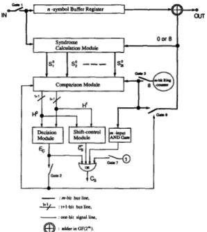
Based on the modified step-by-step decoding algorithm, a structure of sequential decoder is presented. Fig. 1 shows the functional block diagram of the decoder, which comprises a syndrome calculation module, a comparison module, a decision module and a shift-control module. The syndrome calculation module is used to calculate the syndrome values SI, Sa,
. . .
,
Szt. The comparison module is used to obtain the temporarily changed syndrome valuesSi'
and to determine the decision bits hi, 1 = 0 , l ; j = 1 , 2 , .- .
,t
+
1. From these decision bits, the decision module can determine whether the decoding symbol of ~ ( x ) with a testing valuep
is an erroneous symbol. If the corresponding erroneous symbol and its error value have been found, the decoder sends a correcting-bit E, to change the magnitude of the decoding symbol; that is, addingp
to the decoding symbol. The syndrome calculation module has been described well in [3] in detail while the design of the other three modules are described in the following.A. Comparison Module
The comparison module is used to obtain the temporarily changed syndrome values and then to determine the corre- sponding decision vector. The block diagram of the compar- ison module for a t-error-correcting RS code is illustrated in Fig. 2. In Fig. 2, the module first obtains the syndrome values 5'2 or S i , then, a matrix calculation circuit is used to calculate the determinant of syndrome matrices det ( N j )
{ j = 1 , 2 , .
.
.
,
t} and det(flT:+,) where 1 = 0 or 1. When the input are S; (i.e., gate 3 is open), the matrix calculation obtainsd e t ( N j ) and det(N,+,); when the input are Si (Le., gate 3 --o
fi
-
e,
dl.aw1591
Fig. 2. The comparison module of t-error-correcting RS codes.
is closed), then det(N:) and det($+,) are obtained. After finding the values of det(Nj) ( j = 1 , .
.
.
,
t) and det($+,), the decision bits hi can be determined by using t+
1 simple zero-checkers, which are implemented by t+
1 pieces of m-input NOR gates. Besides, in Fig. 2, the decision bits hy must be refreshed if an error value has been found, thereforet
+
1 refresh-circuits are cascaded with the zero-checkers, respectively. In each refresh circuit, gate 4 and the cascaded storage stage are used to save the initial decision bit h; while gate 5 is used to perform the refreshing operation. That is, replace hj" by hi.B. Decision Module
The decision module is used to perform the operations in steps 7) and 8) of the decoding algorithm. When the decision vectors H o and H1 are determined in the comparison module, the decision module can then decide whether or not the testing value
p
of the corresponding symbol is an error value in terms of the difference betweenH o
and H1. The decision module can be easily implemented by employing a logical circuit or a ROM of size 22t+2 x 1 bits. After the decision, the decision module sends a correcting bitE,
= 1 or E, = 0 to control gate 6 for correcting the corresponding symbol, and then refresh the decision bits in the comparison module.C. Shift-Control Module
The shift-control module is used to perform the operations in steps 5) and
-
6) of the decoding algorithm. If the module's output is true, C , = 1, the current decoding symbol must be a correct symbol and then the decoder starts to decode the next symbol. The inputs of the module are the same as that of1592 IEEE TRANSACTIONS ON COMMUNICATIONS, VOL. 41, NO. 11, NOVEMBER 1993
21
cur IN
/’ A modification of the conventional step-by-step decoding
+
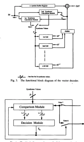
: bmlincfornryndmmcnlucr.Fig. 3. The functional block diagram of the vector decoder.
s y n ” c values
I
By duplicating the syndrome calculation module, the de- coder may work at an equal speed of line rate, with a group delay of n clock cycles. The possible working data rate of this decoder is determined by the computation time of the cell. For example, in the longest computation path of double-error-correcting RS codes, it needs only to perform one addition, one multiplication and several logic gate delays. By the current technology, the calculation time of the comparison and decision modules can be accomplished within only a few hundred nanoseconds and thus, the decoder can work at a line rate up to several millions symbols per second, that is, about several tens of megabits per second. In practice, this decoder is suitable for the short block length RS codes @e., small m and n). Usually, a small n is enough to obtain a high code rate for small t RS codes (e.g., t = 2, and m = 5, n = 31, code rate = 0.87). For these codes of small m, the circuit size of the comparison module and the decision module are very small. The vector decoder avoids the input buffer that required for the sequential decoder and improves the decoding speed, therefore, can work at higher data rate.
VI. CONCLUSIONS
In the modified step-by-step decoding algorithm, the opera- tions in steps 4)-9) constitute an iteration loop for’ testing the n (or less) nonzero values
p.
If steps 3), 5), 6), and 9) are removed, and the testing of nvalues of ,f3 are simultaneously performed in parallel, then the algorithm can be modified as a vector decoding algorithm since the symbols of received word are decoded one at a time with testing a n-tuple vector which is composed of the n possible error values. Based on the vector algorithm, a new vector structure of line speed decoder is presented. In this line speed decoder, the testing of n values ofp
can be performed in space instead of in time iteratively.l
error values in space, a vector structure of line speed decoder has been also proposed for short block length RS codes, which requires only n clock cycles to decode one received word. Therefore, both the sequential decoder and the vector decode can be applied for the nonbinary data transmission and the binary-form data transmission at high-speed data rate. Because of the simplicity in structure and circuit realization, these two types of decoders may be easily implemented in one chip by using VLSI technology.
REFERENCES
1
The functional block diagram of the vector decoder, as shown in Fig* 37 is “posed Of
and n pieces of identical cells where every cell is integrated by a comparison module and a decision module with a fixed
testing and
decision module are the same as that described in Section VI.
[l] W. C. Gore, “Transmitting binary symbols with Reed-Solomon codes,” in Proc. Princeton Conf Inform. Sei. Syst., 1973, pp. 495-497.
[2] S. Lin and D. J. Costello: Jr., Error Control Coding. Englewood Cliffs,
NJ: Prentice-Hall, 1983.
[3] R. E. Blahut, Theory and Practice of Error Control Codes. New York:
Addison-Wesley, 1983.
[4] G. C. Clark and J. B. Cain, Error-Correcting Coding for Digital Com-
munications. New York Plenum, 1981.
syndrome calculation
( y 3 shown in Fig* 4* The
~
IEEE TRANSACTIONS ON COMMUNICATIONS, VOL. 41, NO. 11, NOVEMBER 1993 1 9 3
A.M. Michelson, and A.H. Levesque, Error-Control Techniques for Digital Communication.
I. S. Reed, R. A. Scholtz, T. K. Truong, and L. R. Welch, ‘‘The fast decod-
ing of Reed-Solomon codes using Fermat theoretic transforms and con- tinued fractions,” IEEE Trans. Inform. Theory, vol. IT-24, pp. 100- 106,
Jan. 1978.
H. Okano and H. Imai, “A construction method of high-speed decoder using ROM’s for Bose-Chaudhuri-Hocquenghem and Reed-Solomon codes,” IEEE Trans. Comput., vol. C-36, pp. 1165-1171, Oct. 1987.
[8] H.M. Shao, T.K. Truong, L. J. Deutsch, J.H. Yuen, and I.S. Reed, “A VLSI design of a pipeline Reed-Solomon decoder,” IEEE Trans. Comput., vol. C-34, pp. 393-402, May 1985.
[9] J. L. Massey, “Step-by-step decoding of the Bose-Chaudhuri-Hocqueng- hem codes,”IEEE Trans. Inform. Theory, vol. IT-11, pp. 580-585, Oct.
1965.
[lo]
S. W. Wei and C. H. Wei, “High speed hardware decoder for douhle- error-correcting binary BCH codes,” IEE Proc., vol. 136, Pt. I,pp. 227-231, June 1989.
Cam- bridge, M A M.I.T. Press, 1972, 2nd ed.
New York Wiley, 1985.