IBEE PHOX"IS TECHNOLOGY LEITERS, VOL. 7, NO. 8, AUGUST 1995 923
In-service Supervisory EDFA-Repeated Wavelength
Division Multiplexing Transmission
System
Y.
K.
men,
W.
Y.
Guo,
W.
I. Way,
Senior Member, IEEE,and
S.Chi
Absfmct-An in-service supervLsory wavelength division multi-
p w
mM) 1 'on system is demonstrated for the thst lame. Simultan- fault location and EDFA status-monitoringare achieved without degrading the 2.5 GWs service in a five- EDFA, 365-km, four-WDM-chanuel system.
'
I. INTRODUCTION
HE wavelength division multiplex (WDM) technique
T
combined with erbium-doped fiber amplifiers (EDFA's) is very useful for increasing the capacity of long-distance optical communication systems. With the ever-growing development in EDFA-repeated WDM systems, it is important to use a prac- tical supervisory method that facilitates in-service monitoring and fault-locating capability. Three methods for in-service monitoring and fault-locating have been demonstrated for single-channel systems [ 11-[4], but demonstration for multi- channel systems has not yet been reported. In this letter, an in- service supervisory EDFA-repeated four-channel transmission system, based on a recently reported WDMed supervision technique [3], [4] and the use of strongly inverted EDFA's [5], is constructed and investigated. To our knowledge, this is the first demonstration of a supervisory and an in-service su- pervised WDM transmission system. Simultaneous fiber fault location and EDFA status monitoring and diversity protection can be achieved without degrading the 2.5-GWs service in a five-EDFA, 365-km, four-WDM-channel system.II. SYSTEM
CONFIGURATION AND DESIGN CONSIDERATIONS The supervisory WDM transmission system configuration, shown in Fig. 1, consists of an optical time domain reflectometer (OTDR), a booster amplifier (TOA), five 1.53/1.55-pm WDMed in-line EDFA-repeater pairs, and four optical-preamplifier (ROA) receiver units. Four DFB-laser service signals at 1549, 1551, 1553, and 1555 nm were delivered to the 4 x 1 optical coupler at -6 dBm per channel.A 2.5-Gb/s pseudorandom 23f- 1
NRZ
signal was used to modulate a chirp-adjustable Ti:LiNb03 Mach-Zehnder extemal modulator for the channel at 1551 nm. The otherthree
DFB lasers were runningCW.
An EDFA booster amplifierManuscript received December 16, 1994; revised April 14, 1995. Y. K. Chen is with the Telecommunication Laboratories, Ministry of Trans- portation and Communications Taiwan, Republic of China. He is also with
the Institute of ElectCO-Optical Engineering, National Chia o- k g University. W. Y. Guo is with the Telecommunication Laboratories, Ministry of Transportation and Communications Taiwan, Republic of China.
W. I. Way and S. Chi are with the Institute of Elecm-Optical Engineering and Center for Telecommunications Research, National Chiao-l"g Univer- sity, Taiwan, Republic of china
IEEE Log Number 9412518.
OTDR recovery
Tx1 Tx2 Tx3
Tx4 tro, ckt. / filter PINFET
fig. 1. In-service supervisory WDM system. TOA booster EDFA, ROA optical pmmplifier.
was employed after the coupler in order to compensate the insertion loss of the 4 x 1 optical coupler and to maintain sufficient optical signal power to the transmission line. The
booster ampHer is a 980-nm single-pumped EDFA yielding +12 dBm total output power.
The probe signal of a minor-modified HP8146A OTDR (with a suitable 1535 nm DFB laser diode) is combined with four service signals by a WDM multiplexer. For a pulse width of 12 ps, the OTDR offers a single-way dynamic range of 21 dB with an event resolution of 1.2
km.
In allWDMed in-line repeater stages, the forward OTDR probe signal and backscattered Rayleigh signal are passed around the "unidirectional" working EDFA (''unidirectional" because of one included optical isolator at the output port) and amplified by the bidirectional profection EDFA to increase the OTDR dynamic range.
The
pump laser of a protection EDFA is usedunder normal collditions, and is used to replace the failed pump laser in a working amplifier d e r failure conditions. A local monitoring control circuit is used to activate two mechanical optical switches so that the original failure working pump laser can be replaced.
All
1.53/1.55 pmWDMs
have an averaged channel isolation of -29dB
and back-reflection of -42dB.
The high isolation and low back-reflection features of WDM prevented any mutual crosstalk between transmission and supervision channels.The operation conditions of working and protection EDFA's are different and must be carelidly designed. Unlike single- channel systems that favor saturated operation, multiwave- length silica-based EDFA cascades d e r small interchannel power spread when operated with minimal saturation at very strong inversion levels [5]. Therefore, the operation of each working EDFA was in strong inversion instead of deep sat-
uration. The alumino-germano-silicate EDF in each EDFA, whether the working or protection EDFA, had a NA of 0.20, and a peak absorption at 1532 nm of 5.6 dB/m. The EDF length
(8 m pumped by a 980-nmW laser diode of 50 mw) was the same for all working EDFA's. The average total output power of each working amplifier was about
+
11 dBm. On the other 1041-1135/95$04.00 CQ 1995 IEPE924 E E E PHOTONICS TECHNOLOGY LE'ITERS, VOL. 7, NO. 8, AUGUST 1995 ... ... ... ... . . . . . . . . . . ... . . . . ....,...
4
...: ... j ... ...I ... ..j ... ... : ... .."I ... Dist.: 182.3923 kmb ) ;
... . . .;
,
... LOSS : 16.430 dB ~ ... . . . . . . . . . . . . .. .. . . . . . . . 1 ; . . . . . . . . . . . . ... .. .. . . ... . . j .... .... .... .. . . . . . .. .. ; , ; ; I : . . . . 1 ' : ' ; . .. .. . . . ... ...I /
...; I ;
; j ...., 1.. :. ... . .. .. .Fig. 2. (a) Normal system using a bandpass filter in the first, third, and fifth protection EDFA's to reduce the accumulated forward and backward ASE noise, (b) fault condition with a fiber-breaking at 216 km, and (c) fault condition with a fiber-bending at 183.4 km, and (d) fault condition with pump failure of the first working EDFA.
hand, each protection EDFA (with 4 m EDF pumped by a 980- nm laser diode of 20 mW; the diode has an output capability of 60 mW for pump protection) was operated in small-signal region to reduce the detrimental transient gain compression effect [6] on the OTDR probe pulses. Furthermore, the high
isolation of WDM demultiplexer in each in-line repeater stage contributes to suppress the buildup and accumulation of ASE noise at 1.53 pm in the working amplifier and at 1.55 pm in the protection amplifier. All protection EDFA's gain were designed to just compensate for the interspan loss. The conventional single-mode fiber was used for the transmission fiber in the experiment. The averaged 60.8-km interspan loss was about 19.5 dB, which includes the losses of a WDM multiplexer (0.7 dB), conventional single-mode fiber span (0.21 dB/km), a WDM demultiplexer (0.7 dB), fiber connections (2 dB), and an optical bandpass filter (3.2 dB)
before the protection amplifier. At the receiving end, the demultiplexed service signal after splitting and filtering (1 nm FWHM bandwidth) was detected by an optical-preamplifier receiver unit (-43.2 dBm sensitivity at a bit-error-rate (BER) of lo-'), and measured by the BER test. The receiver unit is composed of a 980-nm pumped EDF preamplifier, a 0.2-nm filter, a PINFET detector, and a clock recovery circuit.
In.
SYSTEM PERFoRMANCE AND DISCUSSIONS Fig. 2(a) shows the observed real-time OTDR trace of the in-service transmission system under normal condition. Note that the Fresnel reflection spike at 365 km coincides with the total link length of the system. The distorted bending OTDR trace at the rear part of each interspan does not affect any reflective fault location of each interspan as illustrated in Fig. 2(b); a fiber break at 216 km was observed and located. Furthermore, Fig. 2(c) shows the OTDR trace of the system when a non-reflective fault (e.g., a5-dB
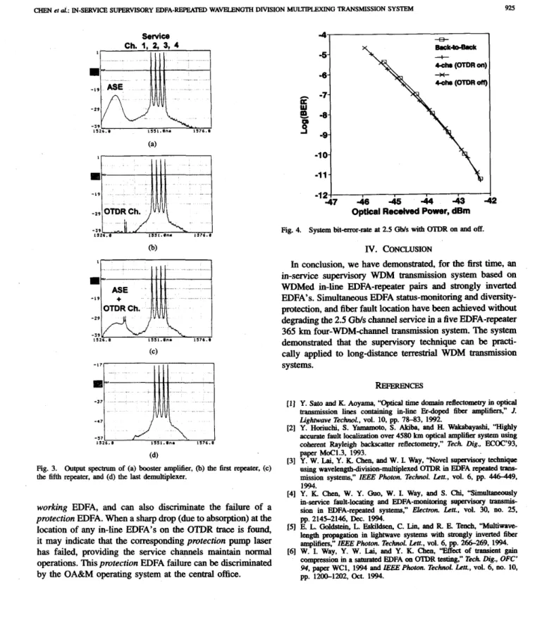
loss resulting from fiber bending) occurred at 183.4 km. This position is right after the third in-line repeater output port. Fig. 2(d) shows the real-time OTDR trace of the system under pump failure condition of the first working EDFA. The sharp drop at the position of the corresponding failed working EDFA's was due to the strong absorption in the unpumped protection EDFA when the failed working pump laser was switched by the local monitoring control circuit to the protection pump laser.Fig. 3(a)-(d) shows the evolution of output signal spectrum through the system link of the booster, the first, fifth in-line repeater, and the last demultiplexer, respectively. The spectra at 1.53 pm band in Fig. 3(b)-(c) consists of the instantaneous spectrum of OTDR probe pulses and the accumulated ASE of the corresponding amplifier stage. In Fig. 3(d), the spec- tra at 1.53 pm band was rejected by the demultiplexer in the demultiplexed signal spectrum. Furthermore, the optical signal-to-noise ratio after six EDFA's (a booster and five in-line EDFA's) amplification was about 28 dB for each channel. Fig. 4 shows the BER performance with OTDR operation on and off. Negligible degradation (0.02 dB) of system performance due to the OTDR supervision was found. The dispersion penalty introduced by the five-repeater 365
km
WDM transmission was about 0.1 dB at BER of lo-".From a cost-saving point of view, a common optical pream- plifier could have been used before the 1 x 4 splitter instead of four separate optical preamplifiers. However, a receiver sensitivity degradation of about 2 dB will be incurred. Fur- thermore, the supervisory system can detect the failure of a
925 CHEN et d : IN-SERVICE SUPERVISORY EDFA-REPEATHI WAVELENGTH DIVISION MULTIPLEXING TRANSMISSION SYSTEM
4 -5- -6- n -7-
c
-8-E
s”
-9- -1 0- -11- -12 Service Ch. 1, 2, 3, 4 1551.0na 1 5 7 6 . 0 (a) -9- 8.ck4o-BWc cchs (OTDR on)+
cob. (0“ I I isz6.e 1551.Una 1 5 7 6 . 8 1 I - 1 9 - 2 9 -J9 1 1 2 6 . 0 I I I I - 1 7 1 - 3 7 1IUUUI
15S1.0n. 1 5 7 6 . 0-‘71-‘ccLl
- 5 7 1 5 2 6 . 0 (d)Fig. 3. Output spectrum of (a) booster amplifier, 0) the 6rst repeater, (c) the fifth repeater, and (d) the last demultiplexer.
working EDFA, and can also discriminate the failure of a protection EDFA. When a sharp drop (due to absorption) at the location of any in-line EDFA’s on the
OTDR
trace is found, it may indicate that the corresponding protection pump laser has failed, providing the service channels maintain normal operations. This protection EDFA failure can be discriminated by the OA&M operating system at the central office.REFERENCFS
Y. Sat0 and K. Aoyama, “OptiIA time domain reflectomtry in optical
Lightwave Technol., vol. 10, pp. 78-83, 1992.
Y. Horiuchi, S. Yamamoto, S. Akiba, and H. Wakabayashi, “Highly accurate fault localization over 4580 km optical ampMer system using coherent Rayleigh backscatter reflectometry.” Tech. Dig., “93, paper MoC1.3, 1993.
Y. W. Lai, Y. K. Chen, and W. I. Way, “Novel supervisorY technique
using wavelengthdivision-multiplexed OTDR in EDFA repeated IXSDS-
mission systems,” IEEE Photon. Technol. Lett., vol. 6, pp. 446-449, 1994.
Y. K. Chen, W. Y. Guo, W. I. Way, and S. Chi, “Simultaneously in-service fault-locating and EDFA-monitoring superviscny transmiS-
sion in EDFA-repeated system,” E&cmn. Lett., vol. 30, no. 25, pp. 2145-2146, Dec. 1994.
E. L. Goldstein, L. Ekkildsen, C. Lin, and R. E Tench, “Multiwave- length propagation in lightwave system with strongly inverted fiber amplifiers,” IEEE Phoron. Technol. Len., vol. 6, pp. 266-269, 1994. W. I. Way, Y. W. Lai, and Y. K. Chen, “EiTect of transient gain compression in a saturated EDFA on OTDR teathg,” Tech. fig., OFC’ 94, paper WC1, 1994 and E E E Photon. Technol. Lett., vol. 6, no. 10, transmission lines containing in-line Erdoped fiber amp”,” 1.