國
立
交
通
大
學
奈 米 科 技 研 究 所
碩
士
論
文
生物分子於矽基礎結構之選擇性組裝
Selective Bottom-up Assembly of Biomolecules onto the
Silicon-based Structures
研 究 生:李坤霖
Kun-Lin Li
指導教授:柯富祥 教授
Prof. Fu-Hsiang Ko
劉增豐 教授
Prof. Tzeng-Feng Liu
生物分子於矽基礎結構之選擇性組裝
Selective Bottom-up Assembly of Biomolecules onto the
Silicon-based Structures
研 究 生:李坤霖 Student:Kun-Lin Li
指導教授:柯富祥 教授 Advisor:Prof. Fu-Hsiang Ko
劉增豐 教授
Prof. Tzeng-Feng Liu
國 立 交 通 大 學
奈 米 科 技 研 究 所
碩 士 論 文
A Thesis
Submitted to Institute of Nanotechnology
College of Engineering
National Chiao Tung University
in partial Fulfillment of the Requirements
for the Degree of
Master
in
Nanotechnology
July 2006
Hsinchu, Taiwan, Republic of China
Acknowledgment
很高興也很幸運的,我在交通大學完成了碩士學位。這段時間裡最重要的人 就是我的指導老師 柯富祥老師。他非常有經驗的將做學問的態度以及方式,一 點一滴的傳授給我,並且不時的要我去注意一些可能會被忽略的細節。跟柯老師 一起合作奈米國家型計劃的楊裕雄、黃調元、林鴻志老師,以及所上的黃國華老 師,也都提供了不少實驗上的幫助或是方向的修正。由衷感謝這些老師們的大力 指導與協助。 生科所的政哲學長以及漢平學弟在實驗的過程中不斷的討論,激發了我一些 新的想法,政哲學長更以自己追求盡善盡美的信念持續鼓舞著我,並且以身作則 的帶領著我,讓我在這段期間非常的有收穫。俊淇學長提供了很多面向的實驗方 向給我,並且把實驗瓶頸嘗試解釋成新的研究方向,開啟了不少新的研究機會。 俊榮、其昌及信強學長在實驗的元件上提供不少資料,讓生醫背景的我能夠順利 切入半導體元件的世界。人豪與界佐學長在我入學之後就一直提供不少照料以及 關心,讓我很順利的融入碩士的生活。十分感謝學長們費心給我在實驗以及生活 上的幫助。 在這邊要特別感謝這些日子來陪伴著我走過的同學及學弟妹們:乙介、志 威、建文、佳典、奕儂、群芳、志杰、敬雅。沒有你們的話,我想我的碩士生活 應該會是非常的苦悶,沒兩下子就被實驗跟論文夾殺出局了吧。這種具備快樂氣 氛以及多發展性的實驗室,沒有你們是不可能成型的。另外感謝宜輝和大鈞在宿 舍的照顧,我想不會有比你們更好的室友了。 最後要謝謝我的父母、妹妹及家人,還有敘諺、嘉欣、如涵、至儀、國馨、 雅雯。你們真的給了我很多的關心以及照顧,讓我能夠在慌亂緊張中得到平穩下 來繼續前進的力量。還有許多沒有辦法提到的人,我真的非常謝謝你們的關心以 及幫助,這些都成為我完成碩士學位的一份動力。生物分子於矽基礎結構之選擇性組裝
研究生:李坤霖 指導教授:柯富祥 教授
劉增豐 教授
國立交通大學奈米科技研究所 碩士班
摘 要
近年來,跨領域的奈米科技發展的非常蓬勃,其中重要的應用之ㄧ便是
結合半導體產業以及生物科技所產生的生物感測器。生物感測器首先必須
將生物分子固定至半導體元件表面,然後靈敏且專一的偵測目標分子。本
論文主要在於研究如何選擇性的將生物分子組裝固定到以矽為相關材料的
結構上面。
我們首先將表面以 APTES 以及戊二醛修飾,固定化螢光分子到不同的基
材上,挑選出最合適於固定化的基材。之後我們成功的將具有活性的酵素
sulfotransferase 固定化至二氧化矽上,而固定化後的 sulfotransferase 依然能
夠保持原來的活性。
我們將固定化技術應用到一個嶄新的奈米線材料金矽化物上面。一開始
先以電子束微影技術以及濕式蝕刻的方法,製作出多晶矽奈米線。接著在
表面沉積金元素並進行退火,將多晶矽奈米線轉變成金矽化物奈米線。利
用王水將未反應的金蝕刻掉之後,金矽化物奈米線以 1,2-ethanedithiol 以及
SulfoSMCC 作表面的修飾,最後固定上各種不同的生物分子。利用螢光或
是電性量測的結果,可以證明金矽化物奈米線是一個良好的生物分子感測
元件。
Selective Bottom-up Assembly of Biomolecules onto the
Silicon-based Structures
Student : Kun-Lin Li Advisor : Dr. Fu-Hsiang Ko
Dr. Tzeng-Feng Liu
Institute of Nanotechnology
National Chiao Tung University
Abstract
In recent years, the interdisciplinary Nanotechnology booms very quickly. Biosensor is one of the applications of nanotechnology that combines the semiconductor industry and
biotechnology. Biosensor must assemble biomolecules onto the surface of semiconductor devices and have high sensitivity and specificity to the target. In this thesis, my study is to selectively assemble biomolecules onto the silicon-based structures.
At first, the surface of various substrates was modified by APTES and glutaraldehyde, and the fluorescent molecules were immobilized onto them. We choose the suitable substrate for immobilization. Thereafter, we immobilize the active enzyme sulfotransferase onto the silicon dioxide, and the enzyme still has origin activity after immobilization.
We propose a novel material gold-silicide to form one-dimensional nanowire for the application of the immobilization technique. We fabricated the poly-silicon nanowire through direct e-beam writing and wet-etching. After depositing a thin gold film by using a sputtering system, we annealed the poly-silicon nanowire to form the gold-silicide nanowire. The resulting wafers were immersed in the aqua regia to remove the unreacted gold. After surface modification by 1,2-ethanedithiol and SulfoSMCC, the various biomolecules are immobilized onto the gold-silicide nanowire. The results of fluorescent images and electrical properties can approve the gold-silicide nanowire is an excellent device for biomolecular detection.
Contents
Acknowledgment
Abstract in Chinese
Abstract in English
Contents
List of Tables
List of Figures
Chapter 1: Introduction
1.1 General Introduction 1.2 Motivation 1.3 Thesis OrganizationChapter 2: Literatures Review
2.1 General Introduction 2.2 Immobilization Technique
Chapter 3: Experiments
3.1 General Introduction 3.2 Experimental 3.2.1 Rhodamine B Immobilization 3.2.2 Sulfotransferase Immobilization3.2.3 Gold-Silicide Nanowire Formation and Binding of Biomolecules
Chapter 4: Results and Discussion
4.1 Immobilization of Fluorescent Materials on Various Substrates
i
ii
iii
iv
vi
vii
1
1 6 78
8 1317
17 21 21 23 2630
304.2 Immobilization of Biomolecules and their Activity
4.3 Immobilization of Biomolecules onto the Gold-Silicide Nanowire and Electrical Properties
4.3.1 The Gold-Silicide Nanowire Formation 4.3.2 The Gold-Silicide Thin Film Property 4.3.3 The Gold-Silicide Nanowire Property
4.3.4 The Immobilization of DNA onto Gold-Silicide Nanowires
4.3.5 The Immobilization of Biotin and Streptavidin onto Gold-Silicide Nanowires 4.3.6 The Immobilization of Mouse-IgG and Anti-mouse IgG onto Gold-Silicide
Nanowires
Chapter 5: Conclusions
References
32 34 34 35 43 51 52 6166
67
List of Tables
Chapter 1: Introduction
Table 1.1………...……….………..3
The chemistries to immobilize various ligands.
Chapter 2: Literatures Review
Table 2.1……….…...14
Methods to immobilize active biomolecules onto surfaces
Chapter 3: Experiments
Table 3.1……….……...26
List of Figures
Chapter 1: Introduction
Figure 1.1………....1
The U.S. market for biosensors and bioelectronics.
Chapter 2: Literatures Review
Figure 2.1………...9
Chemistry is the central science for the development of applied disciplines such as materials research and biotechnology. Materials science, which is based on classic chemical research fields and engineering technologies, has led to enormous advances in tailoring advanced modern materials.
Figure 2.2………..10
A gap currently exists in the engineering of small-scale devices. Whereas conventional top-down processes hardly allow the production of structures smaller than about 100-200 nm, the limits of regular bottom-up processes are in the range of about 2-5 nm.
Figure 2.3………...…...10
Cell labeling with quantum dots and illustration of quantum dot photostability, compared with the dye Alexa 488. In the upper panels, the nucleus is stained red with quantum dots and the actin fibers are stained green with the dye. In the lower panel, the labeling is reversed.
Figure 2.4………...……...11
Nanowire-based electrical biosensors. (a) Scheme showing silicon nanowires functionalized with biotin. (b) On exposure to streptavidin, the nanowires show changes in conductivity. Plot of conductance versus time for a biotin-modified SiNW, where region 1 corresponds to buffer solution, region 2 corresponds to the addition of 250 nM streptavidin, and region 3 corresponds to pure buffer solution. (c) A nanowire that is not functionalized with biotin shows no response. Conductance versus time for an unmodified SiNW; regions 1 and 2 are the same as in b.
Figure 2.5………...……...12
Nanotube-based electrical biosensors. (a) Scheme showing nanotubes functionalized with biotin. (b) Quartz-based microbalance signal of nanotubes after addition of different concentrations of streptavidin. (c) Electrical signal of nanotubes after addition of different concentrations of streptavidin.
Chapter 3: Experiments
Figure 3.1………...……...22
The three main steps of the immobilization of rhodamine.
Figure 3.2………...…...23
Cross-section (not to scale) of the apparatus for sulfotransferase immobilization.
Figure 3.3……….…...24
The three main steps of the immobilization of sulfotransferase.
Figure 3.4………...……...25
The couple reaction catalyzed by phenol sulfotransferase.
Figure 3.5………...……...26
The process of the formation of gold silicide.
Figure 3.6………...………...27 The schematic diagram of Kelvin structure. The nanowire and the pads were made of the same material, gold-silicide.
Figure 3.7………...……...28
The process of immobilization of biomelecules to the gold silicide. R represents rhodamine, biotin, or other biomolecules.
Chapter 4: Results and Discussion
Figure 4.1………...……...30
The patterned wafer of silicon oxide/poly silicon was immobilized with rhodamine. The materials of dark and bright areas were poly silicon and silicon oxide, respectively. (a) APTES-glutaraldehyde modified wafer. (b) The patterned wafer without modification.
Figure 4.2………...……...31
The patterned silicon nitride/poly Si wafer was immobilized with rhodamine. APTES-glutaraldehyde-modified wafer was observed under (a) fluorescent microscope and (b) bright-field microscope with the same field, respectively.
Figure 4.3………...……...32
The comparison of the suspended sulfotransferase with the immobilized one. The immobilized sulfotransferase on the wafer of silicon dioxide have the same activity with suspended enzyme at least 80 minutes.
Figure 4.4………...………...33
The catalytic activity of immobilized sulfotransferase. The reagents were added and the absorbance was kept measuring every 15 minutes. During the period of experiment, there were four times of removal of reagents from the surface.
Inset: All the measurements when the reagents were catalyzed. The duration of removal of reagents was deducted.
Figure 4.5………...………...35
Au-Si phase diagram.
Figure 4.6………...……...36
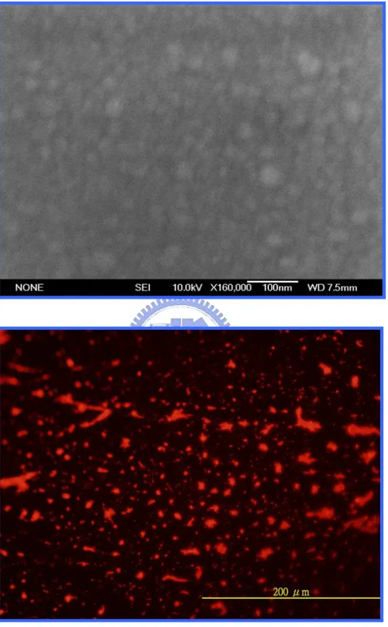
The images of the gold-silicide film annealing at 400℃ by furnace. Upper: the SEM morphology. Lower: the fluorescent morphology.
Figure 4.7………...……...37
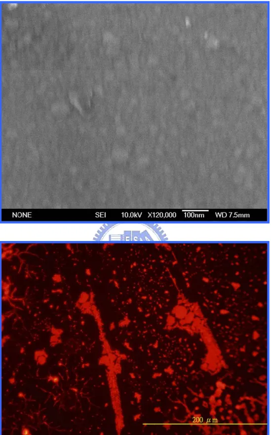
The images of the gold-silicide film annealing at 500℃ by furnace. Upper: the SEM morphology. Lower: the fluorescent morphology.
Figure 4.8………...……...38
The images of the gold-silicide film annealing at 600℃ by furnace. Upper: the SEM morphology. Lower: the fluorescent morphology.
Figure 4.9………...………...39
The images of the gold-silicide film annealing at 400℃ by RTA. Upper: the SEM morphology. Lower: the fluorescent morphology.
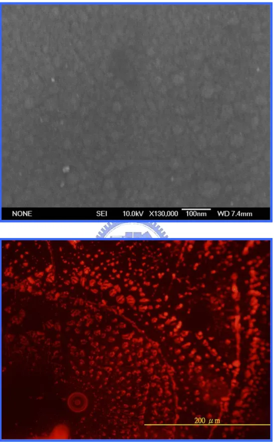
Figure 4.10………...………..……...40
The images of the gold-silicide film annealing at 500℃ by RTA. Upper: the SEM morphology. Lower: the fluorescent morphology.
Figure 4.11……….……...41
The images of the gold-silicide film annealing at 600℃ by RTA. Upper: the SEM morphology. Lower: the fluorescent morphology.
Figure 4.12……….………...42
The images of the gold-silicide film annealing at 650℃ by RTA. Upper: the SEM morphology. Lower: the fluorescent morphology.
Figure 4.13……….………...43
The sheet resistance of the gold-silicide films by RTA and furnace annealing.
Figure 4.14……….…...44
The SEM images of the gold-silicide nanowires with various widths annealing at 300℃ by furnace. The scale bar is 100 nm. (a) 80 nm (b) 100 nm (c) 120 nm (d) 200 nm
Figure 4.15……….……...45
The SEM images of the gold-silicide nanowires with various widths annealing at 400℃ by furnace. The scale bar is 100 nm. (a) 80 nm (b) 100 nm (c) 120 nm (d) 200 nm
Figure 4.16………....45
The SEM images of the gold-silicide nanowires with various widths annealing at 500℃ by furnace. The scale bar is 100 nm. (a) 80 nm (b) 100 nm (c) 120 nm (d) 200 nm
Figure 4.17………....46
The SEM images of the gold-silicide nanowires with various widths annealing at 600℃ by furnace. The scale bar is 100 nm. (a) 80 nm (b) 100 nm (c) 120 nm (d) 200 nm
Figure 4.18……….…...46
The SEM images of the gold-silicide nanowires with various widths annealing at 650℃ by furnace. The scale bar is 100 nm. (a) 80 nm (b) 100 nm (c) 120 nm (d) 200 nm
Figure 4.19……….…...47
The SEM images of the gold-silicide nanowires with various widths annealing at 400℃ by RTA. The scale bar is 100 nm. (a) 80 nm (b) 100 nm (c) 120 nm (d) 200 nm
Figure 4.20………..…..47
The SEM images of the gold-silicide nanowires with various widths annealing at 500℃ by RTA. The scale bar is 100 nm. (a) 80 nm (b) 100 nm (c) 120 nm (d) 200 nm
Figure 4.21……….…...48
by RTA. The scale bar is 100 nm. (a) 80 nm (b) 100 nm (c) 120 nm (d) 200 nm
Figure 4.22……….…...48
The SEM images of the gold-silicide nanowires with various widths annealing at 650℃ by RTA. The scale bar is 100 nm. (a) 80 nm (b) 100 nm (c) 120 nm (d) 200 nm
Figure 4.23……….…...49
The conductance of the poly-silicide nanowire with various widths (a) and after furnace annealing (b~f).
Figure 4.24……….…...50
The sequential mechanism of the formation of gold-silicide during annealing.
Figure 4.25……….……...51
The conductance of the gold-silicide nanowires of various widths with 3’thiol-DNA.
Figure 4.26……….……...52
The images of the gold-silicide pads and nanowire annealing at 300℃ by furnace. Upper: the OM morphology. Lower: the fluorescence of rhodamine.
Figure 4.27……….…...53
The images of the gold-silicide pads and nanowire annealing at 400℃ by furnace. Upper: the OM morphology. Middle: the fluorescence of rhodamine. Lower: the fluorescence of FITC-conjugate streptavidin.
Figure 4.28……….…...54
The images of the gold-silicide pads and nanowire annealing at 500℃ by furnace. Upper: the OM morphology. Middle: the fluorescence of rhodamine. Lower: the fluorescence of FITC-conjugate streptavidin.
Figure 4.29……….…...55
The images of the gold-silicide pads and nanowire annealing at 600℃ by furnace. Upper: the OM morphology. Middle: the fluorescence of rhodamine. Lower: the fluorescence of FITC-conjugate streptavidin.
Figure 4.30……….…...56
The images of the gold-silicide pads and nanowire annealing at 650℃ by furnace. Upper: the OM morphology. Middle: the fluorescence of rhodamine. Lower: the fluorescence of FITC-conjugate streptavidin.
The images of the gold-silicide pads and nanowire annealing at 400℃ by RTA. Upper: the OM morphology. Middle: the fluorescence of rhodamine. Lower: the fluorescence of FITC-conjugate streptavidin.
Figure 4.32……….…...58
The images of the gold-silicide pads and nanowire annealing at 500℃ by RTA. Upper: the OM morphology. Middle: the fluorescence of rhodamine. Lower: the fluorescence of FITC-conjugate streptavidin.
Figure 4.33……….…...59
The images of the gold-silicide pads and nanowire annealing at 600℃ by RTA. Upper: the OM morphology. Middle: the fluorescence of rhodamine. Lower: the fluorescence of FITC-conjugate streptavidin.
Figure 4.34……….…...60
The images of the gold-silicide pads and nanowire annealing at 650℃ by RTA. Upper: the OM morphology. Middle: the fluorescence of rhodamine. Lower: the fluorescence of FITC-conjugate streptavidin.
Figure 4.35………....61
The conductance of the gold-silicide nanowires of various widths with biotin and streptavidin immobilization.
Figure 4.36………....62
The SEM images of the gold-silicide nanowires with various widths annealing at 500℃ by furnace then immobilizing mouse-IgG and hybridizing FITC-conjugated anti-mouse IgG. (a) 80 nm (b) 100 nm (c) 120 nm (d) 200 nm (e) pad.
Figure 4.37……….…...63
The images of the gold-silicide pads and nanowires annealing at 500℃ by furnace. The fluorescence of FITC-conjugated anti-mouse IgG with (upper) and without (lower) surface modification.
Figure 4.38……….…...64
The conductance of the gold-silicide nanowires of various widths with IgG and anti-IgG immobilization.
Chapter 1: Introduction
1.1 General Introduction
The interdisciplinary study of biology, chemistry, and electronics is more and more
important than ever before. Combining biotechnology and semiconductor technology, various
types of biochips and biosensors have now been developed to detect and monitor-specific
binding of biomolecules on the solid-state substrates [1]. The choice of suitable surface for the
purpose of biomolecular immobilization has become an increasingly important biological tool
in recent years. Genomics and proteomics research has elucidated many new biomarkers that
have the potential to greatly improve disease diagnosis [2]. Planar field effect transistor can be
configured as a sensor by binding of a charged species then results in depletion or
accumulation of carriers within the transistor structure [3]. The development of molecular
biology and electronics, as illustrated in Figure 1.1, make the market of biosensors and
bioelectronics keep growing. In this study, we evaluate the suitable substrate often
encountered in the semiconductor technology and adapted it for selective immobilization of
an active enzyme, i.e. phenol sulfotransferase. We also proposed a new sensing material,
(1,817.0) (1,319.4) (1,817.0) (1,319.4)
Figure 1.1: The U.S. market for biosensors and bioelectronics. Source: BCC, Inc; http://www.bccresearch.com
gold-silicide nanowires, with very simple fabrication procedures for biomolecular detection.
The selective immobilization of biomolecules onto silicon-based substrates at very high
efficiency and reliability is the key to combining molecule biology and electronics. The prior
step is to immobilize the molecules of interest onto the sensor chip surface. This
immobilization can be permanent in the form of a covalent bond or transient by means of
capturing. The immobilization technique used depends on the ligand type (protein, sugar,
DNA), the analyte to be used (small or large interactants) and the purpose of the study
(specificity, concentration, affinity, kinetics). In addition, the ligand must retain his biological
activity after immobilization. Information about the ligand size, pI, amino acid composition,
pH stability and possible sites for oriented coupling are beneficial in determining the
immobilization method to be used. The proper formulation is related with the buffer. For most
immobilization methods, a low salt buffer with the exact pH is required. The pH of the
coupling buffer, which will change the surface and ligand charges, regulates the amounts and
speed in which the ligand goes towards the solid surface. In addition, the buffer components
should not interfere with the reaction of immobilization.
Several covalent coupling chemistries are available to immobilize the ligand depending on
the available reactive groups. Primary amine groups (-NH2) present at the side chain of lysine
residues and the N-terminus of each polypeptide chain. Sulfhydryl/ thiol groups (-SH) present
on cysteine residues made available by treating disulfide bonds with a reducing agent or by
modifying lysine residues with a reagent such as SATA. Carbohydrate groups may be
oxidized to create active aldehyde groups (-CHO) for coupling. Covalent coupling is stable
and needs in general no modification of the ligand. The immobilization level is easily
controlled and the ligand consumption is very low. Hence, choosing a correct immobilization
method depends mostly on the nature of the ligand. The Table 1.1 is the recommended
Among these immobilization reactions, amine coupling is the most popular coupling
chemistry. Most macromolecules contain amine groups that can be used in amine coupling.
Situations where amine coupling is less suitable is with acidic ligands (pI < 3.5), ligands
where an amine is in the active site, and with molecules possessing a lot of amine groups. The
choice of thiol coupling depends mostly on the availability of thiol groups on the ligand.
However, it is relatively easy to introduce the thiol groups on the ligand. The thiol chemistry
is more robust than the amine, so the coupling conditions are less critical. The thiol coupling
cannot be used under strong reducing conditions, since the disulfide bond is unstable for such
conditions. The choice of aldehyde coupling can be seen for specific case. For instance,
polysaccharides and glycoconjugates which possess the cis-diols and sialic acids are easily
oxidized to aldehydes.
We used the enzyme sulfotransferase to immobilize onto the surface of silicon oxide.
Sulfotransferases (STs) catalyze the sulfuryl group transferring from the universal sulfuryl Table 1.1: The chemistries to immobilize various ligands.
group donor 3’-phosphoadenosine 5’-phosphsulfate (PAPS) to a wide range of nucleophiles
including endobiotics (i.e., monoamines, phenyl compounds, hormones, proteins and
carbohydrate) and xenobiotics [5,6]. They have been implicated in the activation and
deactivation of hormones and carcinogens through the formation of sulfate conjugates [7]. In
recent research, membrane-associated proteins have been implicated in several biological
processes of great importance, including viral entry into cells, leukocyte adhesion, and
anticoagulation. More generally, enzymatic transformations of cell-surface proteoglycans by
STs appear to trigger vital molecular-recognition and signal-transduction events [8]. The
cytoplasm is a highly reducing environment (~mM GSH) in which protein cysteine residues
are maintained primarily in their thiol state [9]. Redox modification of Cys residues provides
a mechanism for protein regulation. Proteins can be S-glutathionylated [10] or S-nitrosylated
[11], especially during oxidative stress. Oxidative stress is involved in the pathogenesis of
various degenerative diseases including cancer [12].
Redox regulation of recombinant rat phenol sulfotransferase (r-PST) has been shown to
include the modification of cysteine residues [13]. The ratio of the oxidized to reduced form
of recombinant PST protein has been linked to bacterial culture conditions, i.e., growth
temperature and oxygen supply [14]. This suggests that intracellular redox status, which can
be altered by external factors, may regulate PST activity under different conditions.
Biosensors often combine semiconductor devices and molecular receptors, and monitor
the analyte concentration through electric or optic signals. The common biosensor platform is
field-effect-transistor (FET), especially based on high surface/volume ratio materials:
nanowires and nanotubes [3, 15, 16]. Molecular electronic device, however, face a technical
problem that how to reliably interconnect molecules to terminals, and how to characterize and
analyze their electronic properties [17-19]. Similar to planar semiconductor FET, protein FET
(pro-FET) not only belongs to one kind of molecular electronic devices, but also is a pioneer
to the redox properties of a protein, blue-copper azurin, and a back gate modulates the transfer
of redox states. The immobilization of STs could help us study more models and mechanisms
of the STs themselves or apply them to other engineering fields.
The silicon-gold compound is usually considered the most promising eutectic combination
to realize a eutectic bond, because of its low eutectic temperature (363℃), the widespread use
in die bonding and the compatibility with aluminum interconnect [21]. The different
metastable phases with the composition ranges from Au2Si to Au7Si will have differently
structural and electronic properties [22-23]. We used poly-silicon to form gold-silicide
nanowires. The thickness dependence of silicide to sheet resistance and the thermal stability
of silicide on poly-silicon changed the electric properties of silicide [24-25]. The gold-silicide
nanowires were the first time to use to detect biomolecules at least in our knowledge. The
targets we used were streptavidin and antibody, individually.
Streptavidin is a biotin-binding protein isolated from culture broth of Streptomyces avidinii.
It can be crystallized from water or 50% isopropanol. The true native form of streptavidin was
isolated and shown to have a molecular weight of approximately 75,000. Streptavidin binds
four moles of biotin per mole of protein. This corresponds to 16.5-18 mg of biotin bound per
gram of streptavidin. The dissociation constant (Kd) of the complex between streptavidin and
biotin is estimated at approximately 10-15 M, which is one of the tightest non covalent
interactions known between proteins and their ligands. Streptavidin is also one of the most
stable proteins known [26, 27]. Biotin is a water-soluble vitamin found in every living cell in
all organisms. The tissues with the highest amounts of biotin are the liver, kidney and
pancreas. Cancerous tumors have more biotin than normal tissue. Biotin functions as cofactor
of enzymes known as biotin-dependent carboxylases. The role of biotin in carboxylases is to
act as vector for carboxyl-group transfer between donor and acceptor molecules during
carboxylation reaction [28].
neutralize foreign objects like bacteria and viruses. Each antibody recognizes a specific
antigen unique to its target. Immunoglobulins are glycoproteins in the immunoglobulin
superfamily that function as antibodies. There are five types: IgA, IgD, IgE, IgG, and IgM.
The antibodies have two primary functions:bind antigens and combine with different
immunoglobulin receptors specific for them and exert effector functions. In medical
applications, detection of particular antibodies is a very common form of medical diagnostics.
In biochemical applications, antibodies are used for immunological identification of proteins
using western blot, ELISPOT, ELISA (enzyme-linked immunosorbent assay) and flow
cytometry. In these assays, antibodies are used to detect proteins such as cytokines, receptors
or other antibodies. These purified antibodies are often produced by injecting the antigen into
a small mammal, such as a mouse or rabbit [29].
1.2 Motivation
Recently, there has been an increasing demand to find simple and rapid methods for the
detection of specific protein, which can also be used easily in non-specialized laboratories.
The detection of specific protein is critical importance because protein mutation can induce a
couple of diseases. The traditional techniques for protein identification are enzyme-linked
immunosorbent assay [30], fluorescence immunoassays [31], and western blot [32]. The
drawback of above methods is time-consuming, tedious labeling process and poor sensitivity.
Semiconductor processing devices such as nanowires [33] and nanogaps possess the
advantages of low cost and high sensitivity. In this study, we selectively immobilize active
enzyme and propose a self-aligned one-dimensional gold-silicide nanowire to detect the
1.3 Thesis Organization
This thesis is to study the surface modification and immobilization reaction of
biomolecules onto various surfaces. A new kind of nanowire, gold- silicide nanowire, is
proposed to detect proteins which were widely used as the target molecule in the medical
detection or biological studies. For the sake of setting up the experimental system, it requires
lots of knowledge on the basic subjects to accomplish this research, including nanofabrication
technology related to lithography procedures, self-assembly technique, biotechnology, organic
chemistry, molecular biology, and electronics.
In chapter 1, the general immobilization concept is described. The biomolecules to be
immobilized and detected have also been mentioned. Some experimental ideas and techniques
from published literatures are cited and discussed in chapter 2. Chapter 3 briefly states the
experimental reagents and experimental procedures for this research. In chapter 4, various
solid supports were used to immobilize specific protein. We discuss the better support and the
activity of immobilized enzyme. The novel gold-silicide nanowire for detect specific protein
Chapter 2: Literatures Review
In this chapter, we will review some important discoveries in the biosensor and nanotechnology field. Nanotechnology involves the study, manipulation, creation and use of materials, devices and systems typically with dimensions smaller than 100 nm. Nanotechnology is playing an increasingly important role in the development of biosensors. Sensitivity and other attributes of biosensors can be improved by using nanomaterials in their construction. Nanomaterials, or matrices with at least one of their dimensions ranging in scale from 1 to 100 nm, display unique physical and chemical features because of effects such as the quantum size effect, mini size effect, surface effect and macro-quantum tunnel effect. Use of nanomaterials in biosensors allows the use of many new signal transduction technologies in their manufacture. Because of their submicron sizes, nanosensors, nanoprobes and other nanosystems are revolutionizing the fields of chemical and biological analysis, to enable rapid analysis of multiple substances in vivo [1]. “There is plenty of room at the bottom,” as Nobel physicist Richard Feynman pointed out more than 40 years ago [2]. Now we keep developing the room by nanotechnology and the succeeding technology.
2.1 General Introduction
In Figure 2.1, three main disciplines including chemistry, materials science and biotechnology are presented. Merging these disciplines will allow us to take advantage of the improved evolutionary biological components to generate new smart materials and to apply today’s advanced materials and physicochemical techniques to solve biological problems. Both biotechnology and materials science meet at the same length scale (Figure 2.2). On the one hand, biomolecular components have typical size dimensions in the range of about 5 to 200 nm. On the other hand, commercial requirements to produce increasingly miniaturized
microelectronic devices strongly motivate the elaboration of nanoscale systems [3]. Today’s nanotechnology research puts a great emphasis on the development of bottom-up strategies, which concern the self-assembly of (macro) molecular and colloidal building blocks to create larger, functional devices [4]. Novel nanomaterials for use in bioassay applications represent a rapidly advancing field. Various nanostructures have been investigated to determine their properties and possible applications in biosensors. These structures include nanoparticles, nanowires, nanotubes, and thin films. Functional nanoparticles (electronic, optical and magnetic) bound to biological molecules have been developed for use in biosensors to detect Figure 2.1: Chemistry is the central science for the development of applied disciplines
such as materials research and biotechnology. Materials science, which is based on classic chemical research fields and engineering technologies, has led to enormous advances in tailoring advanced modern materials [3].
and amplify various signals [5-9]. The interdisciplinary cooperation of various techniques can solve the human-related diseases.
Colloidal quantum dots are the size of a typical protein, and thus it should be possible to introduce colloidal quantum dots into cells. In 1998, colloidal quantum dots have first been
Figure 2.3: Cell labeling with quantum dots and illustration of quantum dot photostability, compared with the dye Alexa 488. In the upper panels, the nucleus is stained red with quantum dots and the actin fibers are stained green with the dye. In the lower panel, the labeling is reversed.
Figure 2.2: A gap currently exists in the engineering of small-scale devices. Whereas conventional top-down processes hardly allow the production of structures smaller than about 100-200 nm, the limits of regular bottom-up processes are in the range of about 2-5 nm [3].
used for biological labeling [10-11]. It suggested that the photochemical stability and the ability to tune broad wavelength of the quantum dots may make these materials extremely useful for biolabeling (Figure 2.3) [12]. Colloidal quantum dots are robust and very stable light emitters and they can be broadly tuned simply through size variation. In the past few years, a wide range of methods for bio-conjugating colloidal quantum dots was developed [13].
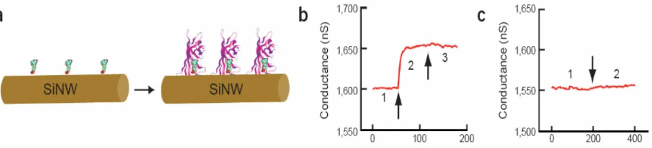
In Figure 2.4, boron-doped silicon nanowires (SiNWs) were reported to create highly sensitive, real-time electrically based sensors for biological and chemical species. The amine and oxide-functionalized SiNWs exhibited pH-dependent conductance that was linear over a large dynamic range and could be understood in terms of the change in surface charge during protonation and deprotonation. Biotin-modified SiNWs were used to detect streptavidin down to at least a picomolar concentration range. In addition, antigen-functionalized SiNWs showed reversible antibody binding and concentration-dependent detection in real time. The small size and capability of these semiconductor nanowires for sensitive, label-free, real-time detection of a wide range of chemical and biological species can be exploited in array-based screening and in vivo diagnostics [14].
Figure 2.4: Nanowire-based electrical biosensors. (a) Scheme showing silicon nanowires functionalized with biotin. (b) On exposure to streptavidin, the nanowires show changes in conductivity. Plot of conductance versus time for a biotin-modified SiNW, where region 1 corresponds to buffer solution, region 2 corresponds to the addition of 250 nM streptavidin, and region 3 corresponds to pure buffer solution. (c) A nanowire that is not functionalized with biotin shows no response. Conductance versus time for an unmodified SiNW; regions 1 and 2 are the same as in b. [14]
Carbon nanotubes have attracted great attentions as nanoscale building blocks for devices. The nano-dimensions, graphitic surface chemistry and electronic properties of carbon nanotubes make them an ideal material for use in chemical and biochemical sensing (Figure 2.5) [15, 16]. Semiconductor nanowires and carbon nanotubes offer the greatest chance yet for creating robust, sensitive, and selective electrical detectors of biological binding events.
Nanofabrication processes typically use variations of the four basic operations of photolithography, thin film growth/deposition, etching, and bonding to create nanometer-sized objects. Nano-electromechanical system (NEMS) technologies are used to produce complex electrical, mechanical, fluidic, thermal, optical, and magnetic structures, devices, and systems with characteristic sizes down to nanometers. NEMS creates and uses systems that have novel properties and functions because of their small and/or intermediate size. DNA hybridization and receptor–ligand binding to microfabricated cantilevers produce surface stress changes that have been measured directly for detection of analytes. A biosensor is made by functionalizing one side of the cantilevers with receptor molecules and then detecting the mechanical bending induced by the binding of a ligand [17].
Nanotechnology is revolutionizing the development of biosensors. Nanotechnology-based Figure 2.5: Nanotube-based electrical biosensors. (a) Scheme showing nanotubes
functionalized with biotin. (b) Quartz-based microbalance signal of nanotubes after addition of different concentrations of streptavidin. (c)Electrical signal of nanotubes after addition of different concentrations of streptavidin [16].
biosensors should be integrated within tiny biochips with on-board electronics, sample handling and analysis. This will greatly enhance functionality, by providing devices that are small, portable, easy to use, low cost, disposable, and highly versatile diagnostic instruments.
2.2 Immobilization Technique
A major advance in materials fabrication technology during the last 10 years has been the development of self-assembly methods [19]. Self assembled monolayers (SAMs) provide well defined structures and chemistries that can be systematically varied. Also, spatially defined arrays of SAMs can be prepared by combining self-assembly with patterning methods such as microcontact printing and photolithography [20]. In addition, SAMs can be used to
immobilize peptides, proteins, and other biomolecules to the surface to prepare the complex surfaces required for well-defined biological experiments. A surface skill used in nature with elegance and precision is the ability to order and organize complex molecules at surfaces. Precision immobilization typically aims to copy nature’s way of organizing molecules and is thus an example of a biomimetic strategy. Possibilities for surface immobilization of
biomolecules are suggested in Table 2.1. The characteristics of successful precision
engineered biorecognition surfaces include the presence of one receptor site, an appropriate surface density of those sites, controlled orientation of the sites, some molecular mobility to enhance ‘‘docking,’’ and stability (of the biomolecular conformation and the film integrity). The ability to inhibit non-specific reactions (in particular, protein adsorption) is also essential to succeed at emulating nature’s surface signal delivery strategy. The ultimate goals in surface immobilization of biomolecules are high activity (functionality) and specificity. The
commonality in systems that show 2-D self-assembly are a relatively simple molecular geometry, a driving force for interacting with a smooth surface, a lateral interactive force between molecules to stabilize them in the crystal and a chemical group that forms the
outermost surface of these systems. The scientific roots of this area of study lie in the Langmuir–Blodgett deposition of lipids and surfactants [21]. The discovery in 1983 of thiol assembly on gold [22] launched an explosion of publications and new discoveries.
Self-assembly of complex organic structures on solid surfaces has been observed for
phospholipids [23], silanes [24], n-alkyl thiols [22, 25, 26], porphyrins [27], nucleotide bases [28], hydrocarbons [29], proteins [30], and many other organic structures.
The choice of a suitable immobilization method is mainly determined by the chemical and physicochemical properties of the immobilization support and of the compound to be
immobilized. The adsorption of compounds onto a surface is the simplest immobilization method. It is based on interactions between local dipoles existing on the interacting molecules. The polarity of the molecule can be stationary due to polar groups, of which –OH, –NH2, –C=O, NH-groups are of particular importance, as they form strong hydrogen bonds. Most frequently biomolecules are bound covalently to the immobilization support through amino groups, which are accessible on the exposed areas of the biomolecules. They react readily with aldehyde and epoxide groups and with carboxylic or amino groups after activation by carbodiimide- or succinimide-derivatives. Take protein as an example, after deposition of the
protein solution an incubation step at room temperature in a humid chamber is sufficient for efficient protein immobilization. This makes these procedures compatible with the fabrication of semiconductor devices.
Silanisation is the most common procedure for the chemical modification of glass surfaces. Amino groups are introduced by aminopropyltriethoxy- (or trimethoxy) silane. Treatment with glutaraldehyde activates the surface by the formation of Schiff bases and free aldehyde groups. Alternatively, bis-sulfosuccinimidyl suberate (BS3) is used as bifunctional agent leading to the activation of the surface by the introduction of succinimidyl groups [31].
Epoxide groups are introduced via 3-glycidoxypropyltrimethoxysilane.Treatment with periodic acid leads to their oxidation to aldehyde groups. Surfaces with aldehyde or epoxide groups sometimes show reduced background signals, as no unspecific electrostatic
interactions are possible, whereas aminofunctionalized surfaces are usually positively charged leading to the unspecific adsorption of negatively charged proteins [32].
Carboxylic groups are present on the surface of carbonaceous electrodes or are generated on the surface of gold layers by self-assembling of thiol compounds, such as
11-mercaptoundecanoic acid [33]. These groups have to be activated to allow covalent coupling of proteins, which is done by incubation with a carbodiimide, such as
1-ethyl-3-(3-dimethylaminopropyl) carbodiimide hydrochloride (EDC) in the presence of N-hydroxysuccinimide (NHS).
Orient immobilization of protein must rely on the specific property of utilizing biochemical affinity reactions. Protein A is a cell surface protein of Staphylococcus aureus, which is capable of binding the Fc domain of immunoglobulins, especially of IgGs [32]. Protein G has similar properties, but is obtained from Streptococcus sp. Group C. Proteins with an
extremely high affinity for biotin are avidin and streptavidin (dissociation constants of approx. 10−15 M). Due to the four biotin-binding sites on each protein molecule a layered structure can be built with a biotinylated surface, a biotin binding protein in the second layer and the
biotinylated capture protein [32]. A protein with hexahistidine tail could binds to nitrilotriacetic acid in the presence of Ni2+ ions [34].
Protein-sensing devices are of increasing importance in the fields of diagnosis, monitoring systems or biological research, as it is realized that proteins are one of the active compounds in organisms. Thus their concentrations, covalent modifications, localizations and activities within or outside cells, tissues or organisms reflect reactions of the organism to its
surroundings, which may be indicative of diseased states, toxic or other adverse effects or for contamination with biohazards, such as microbial toxins.
Chapter 3: Experiments
3.1 General Introduction
All the experiments were proceeded in National Chiao Tung University (NCTU) or National Nano Device Laboratories (NDL). All the equipments were also conducted in our laboratories in NCTU. The reagents were purchased commercially and used by following with the directions unless specially mentioned.
All the reagents were listed alphabetically in the form of “Name {abbreviation; chemical formula; purity; manufacturer}”. Some information will be omitted if not available or not necessary. The following text will use the abbreviation of the reagent.
3-aminopropyltriethoxysilane {APTES; H2N(CH2)3Si(OC2H5)3; 97% purity; Sigma}
APTES was used to modify the property of the SiO2 surface. The ethoxy functional groups of APTES were displaced through formation of covalent bond between the hydrophilic hydroxyl groups of the SiO2 surface and the silicon atom of APTES. This process leads to the formation of a molecular layer of amino groups for bonding with biochemical materials such as DNA molecules.
Acetone {CH3COCH3; ≥ 99.5% purity; Sigma}
Acetone was mixed with DI water to provide an environment that facilitates the APTES binding to the SiO2 surface.
1,3-Bis[tris(hydroxymethyl)methylamino]propane {Bis-Tris propane; CH2[CH2NHC(CH2OH)3]2; >99% purity; Sigma}
This chemical was dissolved to prepare aqueous buffer with an unusually wide buffering range, from approximately pH 6 to 9.5. A solution is usually titrated to the desired pH by using hydrochloric acid. We use this buffer at pH 7 for the sulfotransferase.
Bovine serum albumin makes up approximately 50% of the total protein in serum. It is a non-acetylated protein served as a blocking agent.
Carbonate-bicarbonate buffer capsule {Sigma}
This capsule contains carbonate and bicarbonate powders. Dissolve all the contents in 50 ml ddH2O to yield 0.1 M carbonate-bicarbonate buffer, pH 9.6.
Deionized and distilled water {DI water, ddH2O}
The water we used was purified with filters, reverse osmosis, and deionized system until the resistance was more than 18 MΩ. DI water was used to clean, wash, and be a solvent.
N,N-Dimethylformamide {DMF; HCON(CH3)2; for molecular biology, ≥99% ; Sigma}
It was a solvent for dissolving many hydrophobic organic compounds like rhdamine in the experiments.
1,2-ethanedithiol {HSCH2CH2SH; ≥98.0 %; Aldrich}
This chemical had very unpleasant smell and must be handled in the hood. Any spoil must be cleaned with active charcoal immediately.
Ethylenediaminetetraacetic acid {EDTA; (HOOCCH2)2NC2H4N(CH2COOH)2; 99%
purity; CALBIOCHEM}
EDTA was used to capture cations, such as Mg2+ and Ca2+, that can be a cofactor of certain enzymes which digest and destroy the structures of nucleic acids during experimental processes.
Glutaraldehyde {OHC(CH2)3CHO; Grade I, 25% in H2O; Sigma-Aldrich}
It was a traditional fixative in the histocytometry and electron microscopy. We used it as a linker to combine two amine-contained molecules. This chemical needs to store at -20℃. (+)-Biotin hydrazide {C10H18N4O2S; ~98%; Sigma}
This reagent was for labeling surface functional groups and biologically active molecules such as antibodies, lectins, sugars, nucleic acids or molecules with free carboxylic or keto groups. Typically used for coupling to glycoproteins through the carbohydrate by hydrazone
formation. Store at 4℃.
Hydrogen chloride {HCl; ≥99% purity; Sigma} 1 M HCl in DI water was used for pH adjustment. Hydrogen peroxide {H2O2; ≥30% purity; Sigma}
Hydrogen peroxide was mixed with sulfuric acid to form piranha solution which cleaned the wafer surface.
Potassium p-nitrophenyl sulfate {NO2C6H4OSO2OK; Sigma}
p-nitrophenyl sulfate was the substrate for chromogenic sulfotransferase or sulfatase.
β-naphthol {C10H7OH; 99% purity; Aldrich}
β-naphthol was the substrate for the fluorometric assay of phenol sulfotransferase. Phenol sulfotransferase (EC 2.8.2.9), from Rattus norvegicus
This enzyme is a gift from Prof. Yuh-Shyong Yang, college of Biological Science and Technology, NCTU. Professor Yang studied sulfotransferase for a couple of years. His lab focuses on the reaction mechanism of enzymes, the development of the enzyme chip, and enzyme engineering.
3’-phosphoadenosine 5’-phosphate {PAP; C10H15N5O10P2; ~97%; Sigma}
This chemical was also a substrate of sulfotransferase.
Phosphate-buffered saline tablets {PBS, 1X; CALBIOCHEM}
PBS, a biological buffer solution, was used to increase the selectivity of the DNA chips by washing away any non-hybridized nucleic acids. This chemical is dissolved in one liter ddH2O to yield 10 mM phosphate buffer, pH 7.4, 140 mM NaCl, 3 mM KCl.
Rhodamine B amine {C28H31N3O3; Sigma}
This chemical had fluorescent property and was reactive to the functional group of aldehyde. It was very light-sensitive and must be store at 4℃. During using it, keep from light with aluminum foil.
Sodium tetraborate decahydrate {Na2B4O7
.10 H
2O; 99.5%; Sigma}This chemical was dissolved in DI water as the concentration of 50 mM, providing the buffered environment.
Sodium chloride {NaCl; ≥ 99.5%; Sigma}
Sodium chloride was used to prepare SSC or other biological buffer. Sodium hydroxide {NaOH; 98% purity; Sigma}
10 M Sodium hydroxide in DI water was used to adjust the pH of the HEPES/ EDTA buffer solution.
Sodium phosphate dibasic dihydrate {NaH2PO4; ≥99.5%; Riedel-deHaën}
Sodium phosphate solution was a widely used biological buffer. This chemical was also an ingredient of PBS.
Standard sodium citrate buffer {1X SSC buffer; 0.15 M NaCl, 0.015 M Na citrate, pH 7; Sigma}
SSC was a kind of biological buffer and controlling the stringency of hybridization. SSC was prepared as stock of 20X concentration and dilute with DI water to the desired
concentration for use.
Streptavidin−FITC from Streptomyces avidinii {essentially salt-free, lyophilized powder, ≥ 5 units/ mg protein; Sigma}
This protein had a high affinity for biotin. Prior to use, the powder needed to dissolve in the PBS. It must be stored at -20℃.
Sulfosuccinimidyl 4-[N-maleimidomethyl]-cyclohexane-1-carboxylate {sulfoSMCC; C16H17N2NaO9S; Sigma}
SulfoSMCC was water soluble, non-cleavable and membrane impermeable crosslinker. It contains an amine-reactive N-hydroxysuccinimide (NHS ester) and a sulfhydryl-reactive maleimide group.
Sulfuric acid {H2SO4; 98% purity; Sigma}
Sulfuric acid was mixed with hydrogen peroxide in a 3:1 ratio to remove impurities on the surface of the wafer or devices. This material was very corrosive and dangerous. We must handle it with carefulness and patience.
Tetramethyl ammonium hydroxide solution {TMAH; (CH3)4N(OH); semiconductor
grade}
0.262 N TMAH is used as the developer for positive and negative resist. Tris(hydroxymethyl)aminomethane {Tris base; NH2C(CH2OH)3; ≥99.8%;
Sigma-Aldrich}
This reagent is often used as a buffer with EDTA at the ratio of 10 for DNA. The useful pH range is 7-9.
Tween 20 {Polyethylene glycol sorbitan monolaurate; Sigma}
Tween 20 was a non-ionic detergent to control the stringency of hybridization.
3.2 Experimental
The experiments are divided into three parts. There are special reagents or machines in every individual section. They will be mentioned in detail and some other supplements will be described in the following text as well. During the experiments, the latex gloves, masks, and protective clothing must be dressed in order to avoid unexpected dangers.
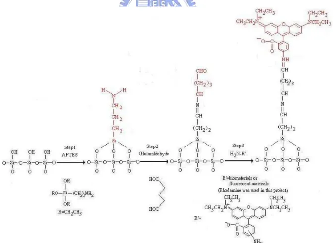
3.2.1 Immobilization of Rhodamine B
The interface and system integration must build on the stable immobilization between the nanoelectronic devices and biomolecules. The first run was to assemble fluorescent molecule onto the patterned wafer. We used two types of patterned wafers, one was the poly silicon and
silicon dioxide, the other was poly silicon and silicon nitride. Figure 3.1 illustrates the procedures to immobilize rhodamine B, a red fluorescent dye, onto the silicon dioxide for the patterned wafer [1]. The procedure of immobilization of rhodamine B was divided into three steps. Step 1 was cleaned patterned wafer with fresh-prepared piranha solution (H2O2: H2SO4= 1: 3) for 1 hour then the derivatized it with APTES for 30 minutes at room
temperature. The sample was rinsed with ddH2O thoroughly after cleaning and derivatizing, respectively. The temperature of the piranha solution must be hold above 85 ℃ to maintain the oxidizing power. If the temperature dropped, add more hydrogen peroxide or renew the piranha solution. It should be mentioned that piranha solution was very corrosive and
dangerous. We must handle it with carefulness and patience. The solvent of APTES solution was constituted with the proportion of one part of acetone to five parts of ddH2O. We adjusted the pH to 3.5 by adding HCl, and the APTES was added into solvent in the concentration of
5%. Step 2 was to bake the derivatized wafer for 30 minutes at 120℃ followed with immersing it in the linker solution, 2.5 % glutaraldehyde [2], for 30 minutes at room temperature. The sample after linking was rinsed with PBS. The baking was to enhance the bonding of silicon dioxide to the APTES. The 2.5% glutaraldehyde solution was diluted with PBS from the Grade I, 25% glutaraldehyde. Step 3 was to immerse the modified wafer in the rhodamine B amine solution for 16 hours at room temperature. The sample was rinsed with carbonate buffer and ddH2O thoroughly. Finally, these samples were observed by fluorescent microscope. The powder of rhodamine B amine was dissolved in the DMF and adjusted the concentration to 0.1 mM with 0.1 M carbonate buffer, pH 9.6. Because the rhodamine B amine is light-sensitive, the solution should prepare freshly and covered the beaker with aluminum foil.
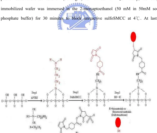
3.2.2 Immobilization of Sulfotransferase
After the successful immobilization of rhodamine B, we immobilize the phenol sulfotransferase [3], a kind of enzyme that catalyzes sulfonation. In order to test the best binding efficiency of the enzyme, we used the wafer with silicon dioxide film as the reaction substrate. The immobilized sulfotransferase on the substrate was illustrated in Figure 3.2.
The teflon ring tightly contacted with the substrate and sealed with silicon resin before all the following procedures to avoid the leakage of the reaction solution. This apparatus is convenient for us to handle the measurement of the reaction solution by pipetman.
The whole procedure was divided into three steps (in Figure 3.3), we cleaned the wafer with piranha solution for 30 minutes, follow with derivatization of the wafer with APTES solution for 30 minutes at room temperature and baking the derivatized wafer at 120 ℃ for 30 minutes in the step 1. In the step 2, we substituted the linker from glutaraldehyde to sulfoSMCC [4] due to the free functional group was thiol, not amine, on the surface of the sulfotransferase. We immersed the sample in the 0.5 mM sulfoSMCC solution for 1 hour at room temperature (SulfoSMCC was dissolved in 50mM sodium borate buffer) followed with phenol sulfotransferase solution (50 mg/L) for 1 hour at 4℃. Finally, the enzyme- immobilized wafer was immersed in the 2-mercaptoethanol (50 mM in 50mM sodium phosphate buffer) for 30 minutes to block unreactive sulfoSMCC at 4℃. At last, the
2-mercaptoethanol solution was removed and added sodium phosphate buffer. In Figure 3.3, the sulfotransferase is depicted in oval shape for convenience and not in the real size. To know whether the enzyme was immobilized or not, observation of the activity of the enzyme was a direct method. The phenol sulfotransferase catalyzed two reaction of the transfer of the sulfuryl group from PAPS and p-nitrophenyl sulfate to the β-naphthol and PAP, respectively (Figure 3.4). The two reactions are coupled to ensure the PAP and PAPS are continuous in the solution and the p-nitrophenol product is still synthesizing. The absorbance of
p-nitrophenol at 400 nm can reflect the activity of the sulfotransferase. We added the reaction
solution prepared by 1mM p-nitrophenyl sulfate, 2 μM PAP, and 50 μM β-naphthol in the 100 mM pH 7 bis-Tris propane to the reaction vessel and measured the absorbance with a UV/Vis spectrophotometer (Hitachi UV/Vis-3300, Japan).
Figure 3.4: The couple reaction catalyzed by phenol sulfotransferase.
3.2.3 Gold-Silicide Nanowire Formation and Binding of Biomolecules
Silicide formation and its properties are very important for biomolecular sensing, especially as metal thin film deposited on silicon at low temperature. When the film becomes thinner, the uniformity and the homogeneity of the silicide layer were challenged. The fabricating sequence of gold-silicide film was first deposited a 500 nm poly-silicon on the
single-crystalline p-type <100> silicon wafer, then a 50 nm gold thin film at various annealing temperatures of interest was applied to the formation of gold silicide film (Table 3.1). The
RTA used annealing time of 3 minutes for any temperatures. The furnace annealing used annealing time of 1 hour. The fabrication process for the one-dimensional gold-silicide nanowire was depicted in Figure 3.5. The p-type single crystalline <100> silicon wafer was used in the following steps. The silicon wafer was grown a film of 5000 Å silicon dioxide as the isolation layer by thermal oxidization furnace. The following 100 nm poly-silicon film was deposited by low pressure chemical vapor deposition. Then, the sample was spin-coated
Fugure 3.5: The process of the formation of gold silicide Table 3.1: The parameters of various annealing temperatures.
temperature (℃) 350 400 500 600 650 300 400 500 600
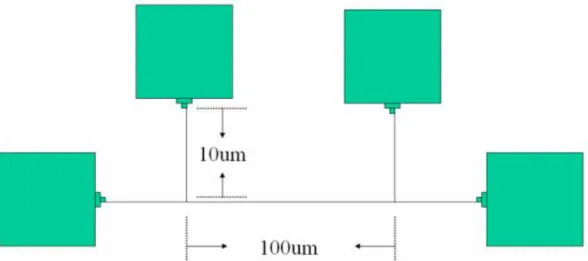
with the negative electron beam resist (NEB-22A) by TEL CLEAN TRACK MK-8 system, and subsequently, electron beam for nanowire patterning (Figure 3.6). Bridge structure constitutes of four pads and three nanowires, the length of nanowire is fixed 100 μm and the width of nanowire ranges from 80nm to 200nm. The electron beam exposure was carried out by Leica WePrint 200 e-beam and wet development was by TMAH solution. The poly-silicon film was etched by LAM TCP 9400SE, and the negative resist was stripped by thermal ozone (Fusion Ozone Asher) and dipped in the mixed solution of H2O2:H2SO4(1: 3) for 10 min. In this moment, the patterned poly-silicon nanowire was ready to thermally deposit 10 nm gold thin films by thermal coater. After the deposition of gold thin film, we annealed the nanowire at various temperatures of interest (Table 3.1), the device was then immersed in the aqua regia (HCl: HNO3= 3: 1) solution to remove the un-reacted gold metal. We used the HP-4156 analyzer to characterize the electrical signal of the patterned Kelvin structure, four pads for probing and a single nanowire for measuring the electrical property.
Figure 3.7 illustrates the surface immobilization of rhodamine or biotin on the gold-silicide nanowire. All the experiments here were proceeded at room temperature. We washed the gold-silicide nanowires with ddH O, ethanol, and acetone in order. Then, the nanowire was
Figure 3.6: The schematic diagram of bridge structure. The nanowire and the pads were made of the same material, gold-silicide.
immersed in the 5% 1,2-ethanedithiol of DMF solution for 30 minutes. After DMF, ethanol, and ddH2O washing, the sample was again immersed in the 0.1 % sulfoSMCC solution for one hour. SulfoSMCC was dissolved in the 100 mM sodium phosphate buffer, pH 6.8. The sample also washed with sodium phosphate buffer after immersion. In order to confirm the success of surface modification, we used the 10 mM rhodamine in the pH 9.6 carbonate buffer to covalently bond with the sulfoSMCC for 2 hour and washed with carbonate buffer
followed with ddH2O. Due to the extremely high affinity of biotin-streptavidin interaction, the pre-assembled biotin molecule can recognize the FITC-conjugated streptavidin molecule in the solution. The gold-silicide nanowire washed and immersed in the 1,2-ethanedithiol and sulfoSMCC as above procedure and was ready to assemble with hydrazide-biotin. The hydrazide-biotin was dissolve in the DMF at 50 mM and dilute to 5 mM with 100 mM
sodium phosphate, pH 7.5. The nanowire was immersed in the biotin solution for 2 hours and Figure 3.7: The process of immobilization of biomolecules to the gold silicide. R represents rhodamine, biotin, or other biomolecules.
also washed with sodium phosphate buffer to removal unbound biotin. The last step was to immerse the biotin-assembled nanowire in the 0.1 % FITC-streptavidin solution for 2 hours. FITC-streptavidin was dissolved in the PBS and dilute with the mixture of pH 7.2 10 mM phosphate-buffered saline, 0.05 % NaN3, 0.15 M NaCl, and 0.1 % Tween 20. All the results will be shown in chapter 4.
In addition to biotin-streptavidin system, we also immobilized other biomolecule, IgG. IgG is a kind of immunoglobulin for humoral immunity. It has a strong affinity to its antigen. In this experiment, we used mouse-IgG as the antigen and donkey anti-mouse IgG as the antibody. The gold-silicide nanowire was cleaned then modified by 1,2-ethanedithiol and sulfoSMCC as previously mentioned procedure. The modified gold-silicide nanowire was immersed in the 5 μg/ ml mouse-IgG solution in 1X PBS, pH 7.0 for 2 hours. After washing with PBS for 3 times, we blocked the device with 1% BSA solution in PBS, pH 7.0 for one hour. The device also washed 3 times by 2% Tween 20 and 0.1% BSA in PBS. The 0.4 μg/ ml donkey FITC-conjugated anti-mouse IgG solution was added to immerse the device for two hours. At last, the device washed by 2% Tween 20 and 0.1% BSA in PBS for 3 times then ddH2O and immediately observed under fluorescent microscope followed with the
Chapter 4: Results and Discussion
We have successfully evaluated the capability of immobilization on the various state-of-the-art substrates for the semiconductor industry. The fluorescent images have suggested that the suitable substrate is silicon dioxide. We also successfully fabricated gold-silicide nanowires by using traditional furnace annealing methods and immobilized rhodamine or biomolecules onto them.
4.1 Immobilization of Fluorescent Materials on Various Substrates
Figure 3.1 was the whole procedures for the selective immobilization of model rhodamine molecule onto various surfaces. The free hydroxyl groups of silicon oxide could react with APTES and leave a free amine group on the surface. The active aldehyde groups of glutaraldehyde will react with the primary amine groups to form imine bonds. The remained
Figure 4.1: The patterned wafer of silicon oxide/poly silicon was immobilized with rhodamine. The materials of dark and bright areas were poly silicon and silicon oxide, respectively. (a) APTES-glutaraldehyde modified wafer. (b) The patterned wafer without modification.
aldehyde groups on the glutaraldehyde could react with primary amine containing molecules such as amine-rhodamine. It was deserved to mention that we have tried three types of substrates in common use for the semiconductor industry to choose the best substrate for the binding candidate. This strategy will help us to design the pattern from the semiconductor devices, such as the nanowires and nanogaps of the sensor.
In Figure 4.1a, the appearance of fluorescent rhodamine molecule on the silicon dioxide patterns is shiny. On the contrary, the poly-Si region exhibits color. Figure 4.1b was the image of no surface modification. The same dark image over the whole sample represented no signals of fluorescence. This observation clearly suggests the rhodamine can be only assembled onto the SiO2 surface. The surface without any APTES and glutaraldehyde modification can not conducted a selective assembly. As for the fluorescent image of the patterned wafer of silicon nitride and the poly silicon in Figure 4.2a, there is no significant fluorescent signal, except for the contamination of the particles. The optical image of the same field in Figure 4.2b showed the pattern on the wafer. As a result, the silicon dioxide was the best material to bind biomolecules by the procedures.
Figure 4.2: The patterned silicon nitride/poly Si wafer was immobilized with rhodamine. APTES-glutaraldehyde-modified wafer was observed under (a) fluorescent microscope and (b) bright-field microscope with the same field, respectively.
4.2 Immobilization of Biomolecules and their Activity
Once the model rhodamine molecule is successful immobilization, the phenol sulfotransferase is also ready to be assembled. The surface of sulfotransferase contains several thiol groups, so the attachment by amine group to glutaraldehyde liker is not feasible. We use the sulfoSMCC linker to immobilize the active enzyme. The sulfoSMCC contains an amine-reactive N-hydroxysuccinimide group and a sulfhydryl-reactive maleimide group. The former could react with the primary amine group of APTES, and the latter could react with the thiol group on the sulfotransferase.
The activity of the immobilized enzyme is compared with the suspended enzyme in Figure 4.3. The accumulation of the absorbance is the same within the duration of 80 minutes and reaches the absorbance plateau at 0.17 thereafter. This observation can be explained that the immobilized enzyme was locally collected on the surface of wafer, and the reactants and products were passed in and out by diffusion. When the concentration was saturated near the surface, the enzyme could not catalyze more substrates but the products intervened in the
Figure 4.3: The comparison of the suspended sulfotransferase with the immobilized one. The immobilized sulfotransferase on the wafer of silicon dioxide have the same activity with suspended enzyme at least 80 minutes.
0.00 0.05 0.10 0.15 0.20 0.25 0.30 0.35 0 50 100 150 200 250
Accumulation time (min.)
Ab
so
rb
an
ce
Suspe nde d e nz yme Immobiliz e d e nz yme
activity of the enzyme. Finally, the enzyme could only catalyze the same amounts of substrates and record the same absorbance.
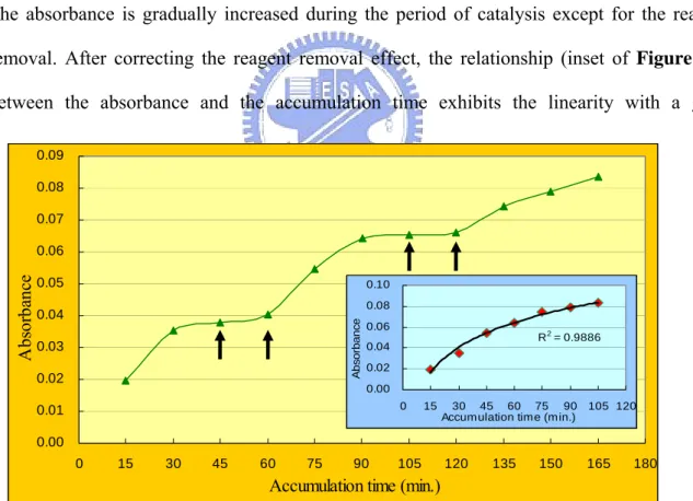
Is the process of immobilization reversible and releasing a portion of enzyme into the solution? We added the reagents and let the sulfotransferase catalyze them, measured the absorbance at 400 nm every fifteen minutes. During the measurement, we make the reagents to be reacted and then removed into the eppendorf every two measure points (Figure 4.4). When the reagents were removed, phosphate buffered saline was added to maintain the environment around the enzyme. Because the reagents were the same in the whole experiment, the raise of absorbance was caused by the catalysis of sulfotransferase. Figure 4.4 also clearly suggests the activity of immobilized sulfotransferase enzyme is still existed up to 160 minutes. The absorbance is gradually increased during the period of catalysis except for the reagent removal. After correcting the reagent removal effect, the relationship (inset of Figure 4.4) between the absorbance and the accumulation time exhibits the linearity with a good
0.00 0.01 0.02 0.03 0.04 0.05 0.06 0.07 0.08 0.09 0 15 30 45 60 75 90 105 120 135 150 165 180
Accumulation time (min.)
A
bs
or
ban
ce
Figure 4.4: The catalytic activity of immobilized sulfotransferase. The reagents we added and the absorbance was kept measuring every 15 minutes. During the period experiment, there were four times of removal of reagents from the surface.
Inset: All the measurements when the reagents were catalyzed. The duration of removal of reagents was deducted.
R2 = 0.9886 0.00 0.02 0.04 0.06 0.08 0.10 0 15 30 45 60 75 90 105 120 Accumulation time (min.)
A
bs
orbanc
![Table 2.1: Methods to immobilize active biomolecules onto surfaces [18]](https://thumb-ap.123doks.com/thumbv2/9libinfo/8609492.190621/29.892.144.796.182.470/table-methods-immobilize-active-biomolecules-surfaces.webp)