Study of efficiency droop in InGaN/GaN light emitting diodes with
V-shape pits
Chiao-Yun Chang, Heng Li and Tien-Chang Lu*
Department of Photonics & Institute of Electro-Optical Engineering, National Chiao Tung
University, Hsinchu 30050, Taiwan
* Corresponding author. E-mail address: [email protected];
Tel.: +886-3-5131234; fax: +886-3-5727981
ABSTRACT
We invesstagated the relationship between the emission efficiency of InGaN/GaN multiple quantum wells (MQWs) and the V-shape pits (V-pits) forming along the threading dislocation (TD). The thinner InGaN/GaN MQWs on the side walls around V-pits would create higher local energy barriers, which can resist the carriers trapped into the non-radiative recombination centres within TDs. By inserting different InGaN/GaN superlattice (SLS) layers below the MQWs, sizes of V-pits could be properly controlled. It was found that the V-pit size on InGaN MQWs increased with increasing SLS layers, which could decrease energy barriers. On the contrary, the shorter distance between the TD center and V-pit boundary would increase the carrier capturing capability of TDs in smaller V-pits. By properly controlling the V-shape defect formation, the best internal quantum efficiency of about 70%f was found in the MQWs with underlying 15 periods SLS layers.
Keywords: V-pit defect, internal quantum efficiency (IQE), droop efficency
1. Introduction
InGaN/GaN light emitting diodes (LEDs) are now widespread used in solid-state lighting, because of their high luminescence efficiency and potential to replace traditional lighting sources [1]. However, there are plenty threading dislocations (TD) occurred during the epitaxial process due to lattice mismatch between the GaN and sapphire substrate [2]. The high threading dislocations density will lead to the enhancement of non-radiative recombination centers and current leakage paths [3]. Despite pattern sapphire substrates (PSS) are applied to reduce the TD density, dislocation
density as high as around 108 cm-2 is typically observed. The previous reports showed that TDs could form V-shape pits (V-pits) on InGaN multiple quantum wells (MQWs). It has the narrower MQW on the inclined V-pit planes, forming energy barriers to effectively block carriers into TDs to retain the emission efficiency [4]. Therefore, it’s inevitable to study the effect of defects on the blue LED efficiency. Meanwhile, the formation of V-pits also help to increase the light extraction efficiency because of the inverted hexagonal inclined planes [5-7]. In addition, the p-type GaN right on top of V-pits has been claimed to show lower Mg incorporation and the localized high resistance could effectively block the current leakage to TDs [8-9] . Furthermore, the formation of V-pits in MQW could facilitate hole injection into deeper QWs to uniformly distribute hole carriers in active layers to improve the efficiency droop [10]. In this study, the relationship between the light emission efficiency of InGaN/GaN MQWs and V-pits formation was systematically analysed. In order to clarify the effects of V-shape pits, we inserted different periods of InGaN/GaN superlattice (SLS) layers ranging from 0, 10, 15, 30 and 60 below the MQWs to control the properties of V-shape pits.
2. Experimental procedures
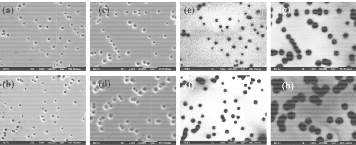
The epitaxial structures including 3.5 μm un-doped GaN (u-GaN) and 2 μm n-doped GaN (n-GaN) layers were grown on the c-plane pattern sapphire substrate (PSS) by metal-organic chemical vapor deposition. Then, four types of samples of InGaN/GaN SLS layers with different periods ranging from 0, 10, 15, 30 and 60 were grown on the n-GaN layer. The thickness of one superlattice period was about 6 nm. Fig. 1(a) and (b) show the top-viwe scanning electron microscopy (SEM) image of 10 and 60 pairs InGaN SLS samples. It can be clearly observed the presence of V-pits on the surface of SLS layer and the V-pit size increased with increasing the pairs of SLS. In the following, the InGaN/GaN MQWs were grown and comprised with first 6 pairs of shallower MQWs with In composition of about 10% and then 9 pairs of deeper MQWs with In composition of about 20 %. The thickness of InGaN well and GaN barrier were 2.8 nm and 13 nm, respectively. Again, the V-shape pits were observed for all samples by using the optical microscopy (OM) of BX50 Olympus Microscope and SEM. Then, the optical properties of InGaN MQWs with varing V-pit size were characterized by using photoluminescence (PL), and cathodoluminescence (CL) measurement.
3. Results and discussion
Fig. 1(c) shows the OM image of PSS rendering a hexagonal lattice pattern. The diameter of a circle basis was about 3 μm and the lattice constant was about 4 μm. The spatial frequency of the PSS could be calculated by Fourier transform. The reciprocal space of Fig. 1(d) clearly shows a 30-degree rotated hexagonal lattice compared with Fig. 1(c). The V-pit distribution on MQWs with 15 pairs SLS was investigated by SEM measurement as shown in Fig. 1(e). The V-pit density was approximately 1.6×108 cm2 and a similar order of V-pit density was observed in all other samples.
could be draw TD would ex from the term of PSS.
Fig. 1(a) the t SEM–image of space distributi (f) Reciprocal s Figs. 2 template of 1 The diameter 330-470 nm, shown in Fig represented t MQWs with the fact that t TD to reduce InGaN SLS s wn due to the xtend along th mination of thr top-view of SE f 60 pairs InGaN ion of PSS by a space distributi (a)-(d) show 0, 15, 30 and s of V-pit size respectively. g. 2 (e)-(g). the non-radiat 10 pairs SLS the V-pit size e the emission so that the ems
fact that the e c direction o reading edge d
EM–image of 1 N/GaN SLS wi applying the Fo ion for the morp
the top view 60 pairs SLS e on MQWs w
The monoch The dark spo tive recombin showed weak could be so sm n intensity. On ssion area of I threading edg originating fro dislocation [1 10 pairs InGaN ith formation of ourier transform phology of MQ of SEM–ima . The V-pit si with 10, 15 30 hromatic CL-im ots basically nation centers ker emission i mall on the sa n the contrary InGaN MQWs ge dislocation om the flat c-p 1]. Consequen N/GaN SLS wi f V-pit grown o m of OM-image QW with V-pits
age for InGaN ize on MQWs 0 and 60 pairs mages of MQ relected the s. However, f intensity than ample with 10 y, the V-pit siz
s was greatly n would domin plane region o ntly, V-pits di ith formation o on PSS. (c) OM e in (c). (e) Top by applying the N/GaN MQWs s increased wi SLS were 130 QWs with 10, positions of for the region
those with 15 0 pairs SLS th
ze were too la reduced.
nate the forma of PSS and tri istribution nat
of V-pit grown M-image for the p view of SEM– e Fourier transf s with format ith increasing 0- 250 nm, 15 15, 30 and 6 V-pits show ns without V-5 and 30 pairs hat carriers cou
arge on the In ation of V-pit iggered the V turally related on PSS. (b) t pattern of PSS –image of MQW form of SEM-im tion of V-pits the numbers o 50-270 nm, 22 60 pairs SLS a wn in Figs. 8(
-pits, the sam s SLS. This co uld be easier t nGaN MQWs t. This kind o V-pit formation d to the pattern
the top view o . (d) Reciproca Ws with V-pits mage in (e). grown on the of SLS layers 20-350 nm and at 450 nm are (a)-(d), which mple of InGaN ould be due to trapped by the s with 60 pairs f n n f al s. e s. d e h N o e s
Fig. 2 (a) The 15 pairs InGaN InGaN MQW InGaN SLS. (f monochromatic nm of InGaN M Fig. 3(a SLS. The em The shoulder attributed to t create higher as a function InGaN SLS la Since the V-p expected and However, the by the TD to MQWs with was shown in onset of the e have more ch phenomenon behaviours. SEM–image of N SLS. (c) The with 60 pairs f) The plane-vie c CL image at 4 MQW with 60 p a) shows the l mission peak o r emission pea the emission emission ener n of SLS layer ayers. The pea pit size on In d lower local e V-pit size fo o reduce the e 15 pairs SLS n Fig. 2(c) an emission from hances to flow of InGaN M
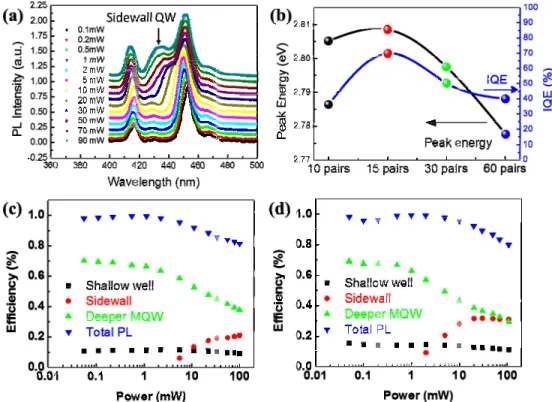
f V-pit for InGa e SEM–image InGaN SLS. (e ew monochrom 450 nm of InGa pairs InGaN SL low tempertur of shallow InG ak at 432 nm of sidewall In rgy in the sem rs at the excit ak energy of s nGaN MQWs energy barrie or the InGaN M emission inten S. In addition, nd (d). It can m the sidewall w over those MQWs. As a aN MQW with of V-pit for In e) The plane-vi matic CL image aN MQW with LS. re PL spectra GaN/GaN MQ was clearly o nGaN/GaN M mi-polar face. tation power sidewall InGaN s increased w ers were then MQWs with 1 nsity. Therefo the normaliz be found that l MQWs on V energy barri a result, a pro 10 pairs InGaN nGaN MQW w iew monochrom at 450 nm of I 30 pairs InGaN versus the ex QWs and deep observed with MQWs on V-sh Fig. 3(b) show of 20 mW an aN MQW redu with increasing formed aroun 10 pairs SLS ore, the best I zed PL emissi t the PL emis V-pits. At a hi ers around th oper V-pit st N SLS. (b) The with 30 pairs In matic CL imag InGaN MQW w N SLS. (h) The citation powe per InGaN/Ga h increasing th
hape pit duo t ws the emissio nd the IQE va uced with incr g pairs of SL nd V-shape p could be so sm IQE value of ion efficiency sion efficienc igh excitation he V-pits, lead tructure could e SEM–image o nGaN SLS. (d) ge at 450 nm o with 15 pairs In plane-view mo er at 10K of In aN MQWs we he excitation to the thinner on peak energ alue of InGaN reasing the num
S, thicker sid its, which cou mall that carri f about 70% w y of InGaN M cy droop of In power, those ding to the o d be enginee
of V-pit for InG The SEM–ima of InGaN MQW nGaN SLS. (g) onochromatic C nGaN MQWs ere at 417 nm power. This p r sidewall qua gy of sidewall N/GaN MQW mbers of InGa dewall quantu uld reduce th iers could be was obtained MQWs with 10 nGaN MQWs e high energy ccurrence of ered to impro GaN MQW with age of V-pit fo W with 10 pair The plane-view CL image at 450 s with 30 pairs m and 450 nm peak could be antum wells to InGaN MQW W with varying aN SLS layers um wells were he IQE values easier trapped in the InGaN 0 and 60 pairs s started at the carriers could serious droop ove the droop h r s w 0 s m. e o W g s. e s. d N s e d p p
Fig. 3 (a) The sidewall InGaN InGaN SLS lay pairs SLS as a deeper and side
The rel investigated. into the non-increased wit contrary, the capturing cap InGaN MQW MQWs with shed light on power depend N MQW as a f yers. (c) The e function of exc ewall of InGaN lationship bet The thinner s radiative reco th increasing shorter distan pability of TD Ws and improv 15 pairs SLS. making high dent PL spectra function of SLS emission efficie citation power a N MQW with 60 tween the em idewall MQW ombination ce SLS layers, w nce between t s. Therefore, ve the droop b We believe th performance I
for the InGaN S pairs at the te ency of intgrate at the temperatu 0 pairs SLS as a mission efficie Ws around V-p entres within t which would the TD center an optimized behavior. In o hat further opt InGaN LEDs N/GaN MQW w emperature of ed PL spectra f ure of 10K. (d) a function of ex 4. Conclu ency of InGa pits could serv the V-pits ori widen the QW r and V-pit bo
V-pit size cou our experimen timiztion of V in the near fu with 30 pairs SL 10K and the IQ for shallow, de The emission e xcitation power usion aN/GaN MQW ve as local ene iginating from W thickness oundary in sm uld be benific nts, the best IQ V-pit structure uture. LS at 10K. (b) QE value of InG
eper and sidew efficiency of int at the temperat Ws and the d ergy barriers t m TDs. The V and decrease maller V-pits cial to preserv QE value of 7 es by using var The emission GaN/GaN MQW wall of InGaN M tgrated PL spec ture of 10K. different V-sh to block the ca V-pit size on I the barrier en would increa e the emission 0% was obtai rious growth c peak energy o W with varying MQWs with 10 ctra for shallow
hape pits was arriers trapped InGaN MQWs nergy. On the se the carriers n efficiency in ined in InGaN conditions can f g 0 w, s d s e s n N n
Acknowledgement
We acknowledge the help of Prof. S. C. Wang and Prof. H. C. Kuo, at National Chiao Tung University for technical support. This work was supported by the MOE ATU program and by the National Science Council of Republic of China in Taiwan under Contract NSC 102-2221-E-009-156-MY3.
Reference
[1] Dupuis, R. D. and Krames, M. R., "History, Development, and Aplications of High-Brightness Visible Light-Emitting Diodes, " IEEE J. Lightwave Technol., 26 (9),1154-1171 (2008).
[2] LeGoues, F. K., "Self-aligned sources for dislocation nucleation: The key to low threading dislocation densities in compositionally graded thin films grown at low temperature, " Phys. Rev. Lett., 72 (6), 876-879 (1994).
[3] Schubert, M. F., Chhajed, S., Kim, J. K., Schubert, E. F., Koleske, D. D., " Crawford, M. H.; Lee, S. R.; Fischer, A. J.; Thaler, G.; Banas, M. A., Effect of dislocation density on efficiency droop in GaInN/GaN light-emitting diodes, " Appl. Phys. Lett., 91 (23) (2007).
[4] Hangleiter, A.; Hitzel, F.; Netzel, C.; Fuhrmann, D.; Rossow, U.; Ade, G.; Hinze, P., " Suppression of nonradiative recombination by V-shaped pits in GaInN/GaN quantum wells produces a large increase in the light emission efficiency, " Phys. Rev. Lett., 95 (12), 127402 (2005).
[5] Yong, A.; Soh, C.; Zhang, X.; Chow, S.; Chua, S., " Investigation of V-defects formation in InGaN/GaN multiple quantum well grown on sapphire, " Thin Solid Films, 515 (10), 4496-4500 (2007).
[6] Tsai, H.; Wang, T.; Yang, J.; Chuo, C.; Hsu, J.; Feng, Z.; Shiojiri, M., " Observation of V defects in multiple InGaN/GaN quantum well layers, " Mater. Trans., 48 (5), 894 (2007).
[7] Shiojiri, M.; Chuo, C.; Hsu, J.; Yang, J.; Saijo, H., " Structure and formation mechanism of V defects in multiple InGaN/GaN quantum well layers, " J. Appl. Phys., 99 (7), 073505 (2006).
[8] Han, S.H.; Lee, D.Y.; Shim, H.W.; Lee, J. W.; Kim, D.J.; Yoon, S.; Kim, Y. S.; Kim, S.T., " Improvement of efficiency and electrical properties using intentionally formed V-shaped pits in InGaN/GaN multiple quantum well light-emitting diodes, " Appl. Phys. Lett., 102 (25), 251123 (2013)
[9] Kim, J.; Cho, Y.H.; Ko, D.S.; Li, X.S.; Won, J.Y.; Lee, E.; Park, S.H.; Kim, J.Y.; Kim, S., " Influence of V-pits on the efficiency droop in InGaN/GaN quantum wells, " Opt. Express, 22 (103), A857-A866 (2014).
[10] Sharma, N.; Thomas, P.; Tricker, D.; Humphreys, C., " Chemical mapping and formation of V-defects in InGaN multiple quantum wells, " Appl. Phys. Lett., 77 (9), 1274-1276 (2000).