UMTS核心網路掠奪性排隊機制之研究
60
0
0
全文
(2) UMTS 核心網路掠奪性排隊機制之研究 A Study on a Preemptive Queueing Scheme in an UMTS Core Network Gateway 研 究 生:陳秋皓. Student:Chiu-Hao Chen. 指導教授:楊. Advisor:Chyan Yang. 千. 國 立 交 通 大 學 資訊管理研究所 碩 士 論 文. A Thesis Submitted to Institute of Information Management College of Management National Chiao Tung University in Partial Fulfillment of the Requirements for the Degree of Master of Business Administration in Information Management June 2004 Hsinchu, Taiwan, the Republic of China. 中華民國 九十三 年 六 月.
(3) U M T S 核 心 網 路 掠 奪 性 排 隊 機 制 之 研 究 學生:陳秋皓. 指導教授:楊千 博士 國立交通大學資訊管理研究所碩士班. 中文摘要. 本論文於第三代全球行動通訊系統(UMTS)之核心網路(Core Network) 中,提出以角色為基礎之佇列(RBQ, Role Based Queueing)掠奪式 (preemptive)排程方法,依據行動使用者之角色而提供不同等級之服務 品質(QoS),並且特別針對於 UMTS 定義之服務品質等級中之背景資 料型態(background traffic)為實驗資料型式;論文中設計一適用於角色 基礎之佇列,一具掠奪性之移入排程方法,及一具優先權式之循環移 出排程方法;利用網路實驗工具 NS2 驗證模擬後,發現 RBQ 排程系 統機制能於不同頻寬假設中,當總閘道器頻寬無法負荷進入之總流量 頻寬時,能夠提供以給定角色為基礎之掠奪性排程;當負荷總流量頻 寬低於閘道器頻寬時,能夠提供以各流量頻寬為基礎之公平性移入效 能。. 關鍵字:全球行動通訊系統,差異性服務,掠奪性排隊機制,角色為 基礎之排隊機制. i.
(4) A Study on a Preemptive Queueing Scheme in an UMTS Core Network Gateway Student:Chiu-Hao Chen. Advisors:Dr. Chyan Yang. Institute of Information Management National Chiao Tung University. ABSTRACT This paper describes a RBQ (Role Based Queueing) preemptive scheduling discipline based on the Core Network in UMTS. RBQ provides diverse quality of service towards to Background data traffic that is defined by UMTS QoS class. In the RBQ system, we design a role based queue, a preemptive enqueue mechanism and a preemptive Round-Robin dequeue mechanism. With NS2 simulation, we figure out that when total flow bandwidth is in excess of gateway bandwidth, RBQ can provide a preemptive scheduling based on the given roles. On the other hand, when total bandwidth is not in excess of gateway bandwidth, RBQ can provide a fair enqueue throughput based on each flow bandwidth.. Keywords: UMTS, Differentiated service, Preemptive queueing scheme, Role Based Queueing (RBQ) scheme. ii.
(5) 誌. 謝. 終於; 兩年的時光,總算能為自己過去的天真畫上沒有遺憾的分號,未來,就將要從這 個分號再開始… 一路走來,要感謝的人太多,爸媽與家人的支持是我永遠的靠山,指導教授楊千 老師讓我見識到學者的風範與涵養,傅學長不辭辛勞的修正我的論文,真心感 謝!還有,感謝芳萍學姊這兩年來的共同挑燈奮戰。 曾經與我共事,與我解惑,與我談天,與我說地的你/妳們,都是我衷心感謝的 對象,不論是正面的鼓勵或是反面的激勵,都絕對給予我無限的收穫與成長。這 一張 A4 白紙真的放不下那麼多人名,請恕我將你/妳們放在我心裡,我會時時將 你/妳們拿出來溫習一番的。^_^ 未來的路,或許寂寞,或許無助,也許未知,引用 Queueing 大師 Kleinrock 詩 中說的 Just join the line of an analytical queue!用我的話再說一次,就是:跟 上人群,做就對了!未來雖然難以掌握,就讓我們一起努力跟上,再跟上吧。. If you want to model networks Or a complex data flow A queue's the key to help you see All the things you need to know. So the next time you feel lonely And wonder what to do, You'll soon feel fine if you join the line Of an analytic queue! - Leonard Kleinrock, <Ode to a Queue>, RFC1121. iii.
(6) Contents 中文摘要.................................................................................................................................................. I ABSTRACT ...........................................................................................................................................II 誌. 謝 ............................................................................................................................................. III. LIST OF FIGURES............................................................................................................................. VI LIST OF TABLES ..............................................................................................................................VII 1. INTRODUCTION ..............................................................................................................................1 1.1 BACKGROUND ................................................................................................................................1 1.2 MOTIVATION ...................................................................................................................................1 1.3 OBJECTIVE ......................................................................................................................................3 1.4 CHAPTERS AND SECTIONS ...............................................................................................................4 2. LITERATURE REVIEW ..................................................................................................................5 2.1 UMTS ............................................................................................................................................5 2.1.1 UMTS Evolution.....................................................................................................................5 2.1.2 A General UMTS Architecture ...............................................................................................7 2.1.3 Core Network Domain in UMTS............................................................................................9 2.2 THE QOS CLASSES........................................................................................................................12 2.2.1 Internet QoS .........................................................................................................................12 2.2.1.1 IntServ.......................................................................................................................................... 13 2.2.1.2 DiffServ........................................................................................................................................ 14. 2.2.2 QoS in UMTS .......................................................................................................................15 2.3 QUEUEING ....................................................................................................................................18 2.3.1 First Come First Serve (FCFS)............................................................................................18 2.3.2 Priority Queueing (PQ) .......................................................................................................18 2.3.3 Stochastic Fairness Queueing (SFQ) ...................................................................................19 2.3.4 Round Robin (RR) ................................................................................................................19 2.3.5 Weighted Round Robin (WRR) .............................................................................................20 2.3.6 Deficit Round Robin (DRR) .................................................................................................21 2.3.7 Weighted Fair Queueing (WFQ) ..........................................................................................22 2.3.8 A Summary of Queueing Schemes ........................................................................................22 3. A PREEMPTIVE QUEUEING SCHEME FOR UMTS BACKGROUND TRAFFIC...............24 3.1 SYSTEM OVERVIEW ......................................................................................................................24 3.1.1 Basic Concept ......................................................................................................................24 3.1.2 Assumptions .........................................................................................................................25 iv.
(7) 3.1.2 UMTS QoS Criteria for RBQ ...............................................................................................25 3.2.2 The Logical Queue Operations in Role Based Queueing Scheme........................................30 3.2.3 Preemptive Packet Switcher Function .................................................................................32 3.2.4 Preemptive Packet Forwarder Function ..............................................................................34 4. SIMULATION RESULTS ANALYSIS...........................................................................................36 4.1 SIMULATION .................................................................................................................................36 4.1.1 Simulation platform .............................................................................................................36 4.1.2 Simulation topology .............................................................................................................36 4.1.3 Simulation Scenario .............................................................................................................37 4.1.4 Bandwidth settings ...............................................................................................................38 4.2 SIMULATION RESULT ANALYSIS .....................................................................................................39 4.2.1 Definitions of Throughput and Packet Drop Rate ................................................................39 4.2.2 Throughput and Packet Drop Rate among the Simulated Background Applications...........40 4.2.2.1 Indoor or Slow Speed Move......................................................................................................... 40 4.2.2.2 Fast Speed Move .......................................................................................................................... 43 4.2.2.3 High Speed Move......................................................................................................................... 45. 5. CONCLUSION.................................................................................................................................48 6. REFERENCES .................................................................................................................................50. v.
(8) List of Figures Figure 1.1 Worldwide Revenue from Non-voice Services .....................................................................2 Figure 2.1 Evolutions from 2G to UMTS (3G) ......................................................................................6 Figure 2.2 Conceptual UMTS Architecture ............................................................................................7 Figure 2.3 UMTS domains .....................................................................................................................9 Figure 2.4 SGSN in CN (R99) ..............................................................................................................10 Figure 2.5 GGSN in CN (R99) .............................................................................................................10 Figure 2.6 A Core Network Domain with HN, SN, TN ........................................................................12 Figure 2.7 IntServ and RSVP ...............................................................................................................14 Figure 2.8 A DiffServ Domain .............................................................................................................15 Figure 2.9 UMTS OoS Architecture .....................................................................................................17 Figure 2.10 A Pseudo Code of WRR ......................................................................................................20 Figure 2.11 A Pseudo Code of DRR.......................................................................................................21 Figure 2.12 A Pseudo Code of WFQ ......................................................................................................22 Figure 3.1 Role Based Queueing Scheme Architecture..........................................................................28 Figure 3.2 RBQ Elements.......................................................................................................................31 Figure 3.3 ENQUEUE Preemptive Packet Switchers Process Diagram.................................................33 Figure 3.4 Preemptive Packet Switcher Function Pseudo Code.............................................................34 Figure 3.5 Preemptive Packet Forwarder Function Diagram .................................................................35 Figure 4.1 RBQS Simulation Topology..................................................................................................37 Figure 4.2 Background Applications’ Throughput as They Require 2MB Bandwidth...........................40 Figure 4.3 Background Applications’ Throughput as They Require 6MB Bandwidth...........................41 Figure 4.4 Background Applications’ Packet Drop Rate as They Require 6MB Bandwidth..................42 Figure 4.5 Background Applications’ Throughput as They Require 374KB Bandwidth........................43 Figure 4.6 Background Applications’ Throughput as They Require 450KB Bandwidth........................44 Figure 4.7 Background Applications’ Packet Drop Rate as They Require 450KB Bandwidth ..............45 Figure 4.8 Background Applications’ Throughput as They Require 60KB Bandwidth..........................46 Figure 4.9 Background Applications’ Throughput as They Require 274KB Bandwidth........................47 Figure 4.10 Background Applications’ Packet Drop Rate as They Require 274KB Bandwidth ............47. vi.
(9) List of Tables Table 2.1 DiffServ class allocated to UMTS QoS class ........................................................................15 Table 2.2 UMTS QoS Classes Attributes ..............................................................................................17 Table 2.3 Comparisons of Scheduling ....................................................................................................23 Table 3.1 UMTS bearer QoS attributes defined for each traffic class ...................................................26 Table 3.2 A mapping between role identification and QoS priority........................................................29 Table 3.3 Logical Queue Elements.........................................................................................................32 Table 4.1 Flow Bandwidth Configuration Table.....................................................................................38. vii.
(10) 1. Introduction 1.1 Background There seemed to be a great sparkle of 3G communication lifestyle when ITU-R (ITU-Radio communication) gave birth to the IMT-2000 (International Mobile Telecommunications 2000) in 1996. In the near future, the following scenes could be imagined. People can watch video streams more fluently, browse websites from the Internet more smoothly, and also download bulky files as fast as in the wired-network using their diverse mobile devices with up to 2Mbps bandwidth supported in 3G system. Hereafter, the mobile communication services provided by 3G are not only voice communications but also tremendous amount of data communications. Several 3G-system standards are proposed. One of the most prospective 3G systems is UMTS (Universal Mobile Telecommunication System) that is proposed by ETSI (European Telecommunication Standard Institute) due to its well system compatible, open-system, vendor-supported and other beneficial features. Therefore, this study would base on the UMTS mobile communication system. Moreover, since there are many mobile communication services would share the limited 3G network resources, the QoS of 3G becomes an important issue. For UMTS, 3GPP has proposed the UMTS QoS architecture and defined four different kinds of QoS classes such as conversational, streaming, interactive, and background class. Each class application has its own bearer service attributes to construct its QoS profile [11].. 1.2 Motivation Because of the limitation of 3G mobile communication bandwidth and the QoS profiles required by diverse mobile services, a proper queueing mechanism in an UMTS core network would be required to support a QoS profile to each mobile 1.
(11) service. In general, the conversational or streaming service applications are most time sensitive and should have the higher priority to allocate 3G bandwidth to ensure voice or video stream transmission smoothly and sequentially. Moreover, the time delay seems not so important for the interactive and background applications in 3G mobile network. Additionally, the packet transmission sequences of these two type applications seem not to be an issue for these two type applications.. Figure 1.1 Worldwide Revenue from Non-voice Services [21] The interactive/background mobile applications include E-Mail, SMS (Short Message System), MMS (Multimedia Message System), and FTP. They would become more and more popular and gain more revenues year by year, shown in Figure 1.1. In UMTS networks, the interactive/background services are supported by a packet-switching transmission and these two services are delay-tolerant applications. Although some queueing schemes have been proposed for 3G conversational and streaming services, but the features of interactive/background services are different. 2.
(12) from conversational/streaming services. These proposed queueing schemes for 3G conversational/streaming services might not be proper for the interactive/background services. Since the interactive/background applications are getting important, it is necessary to propose a queueing scheme for interactive/background applications to support the QoS of interactive/background services. This study would focus on the packet-switching mobile services and proposes a preemptive queueing mechanism to operate in an UMTS core network gateway. With the proposed queueing mechanism operation, the important mobile services with higher transmission priority could preempt the bandwidth of lower priority mobile services to receive better transmission performance.. 1.3 Objective This study would base on the role that user plays to propose a preemptive queueing scheme to support the background service operations in an UMTS core network gateway. According to the users’ importance, different transmission priorities would be assigned to their UMTS background applications to satisfy the required QoS profiles for UMTS users. The proposed queueing scheme would provide an effective mechanism of differentiated service. Several assumptions in this study would be specified as the following: 1. The proposed role-based queueing scheme would aim at the UMTS background applications. The background traffic is generally considered as the traffic type of the lowest delay-sensitive data and the highest packet-loss-sensitive among these four QoS class [17]. 2. The proposed role-based queueing scheme would be operated in an UMTS core network gateway. Its operation domain would be on the packet switching network which corresponds to All-IP Core Network domain in UMTS R5 architecture [20]. 3.
(13) The role-based queueing (RBQ) scheme would base on the status of each user to the different weighted priority to each UMTS background application. There exists a mapping between the status of mobile user and the transmission priority of an UMTS background application. The users’ roles can be divided into three types, such as: Member, VIP and Emergency, each of them has a distinct specific priority from low to high. Therefore, mobile users can choose distinct roles with paying cost to have one relative guarantee performance to deliver traffic packets with the RBQ in an UMTS core network. When the background UMTS packets enter the UMTS core network gateway, the RBQ scheme would base on the priorities received by the background applications to forward the applications’ packets. With RBQ scheme operating in an UMTS core network gateway, differentiated services would be provided according to the role of mobile users. The limited UMTS network bandwidth could be utilized efficiently for the UMTS background applications within the UMTS core network.. 1.4 Chapters and Sections In the following chapters and sections, the overview of UMTS architecture, Internet QoS, and UMTS QoS classes would be reviewed in Chapter 2. A role-based preemptive queueing scheme, called RBQ, in an UMTS core network gateway would be proposed in Chapter3. In Chapter 4, several scenarios would be simulated. The simulation results would be collected and analyzed. At last, the conclusion on this study would be described in Chapter 5.. 4.
(14) 2. Literature Review 2.1 UMTS UMTS is one of 3G mobile communication system proposed by ETSI. For the implementation cost consideration, UMTS system is compatible with GSM system in some infrastructures, it is considered to replace 2G GSM mobile communication system. As digital data communication becoming more important, more mobile data communication applications would be supported by 3G system. In UMTS system architecture, circuit switching and packet switching transmissions are implemented to provide four type mobile communication applications in the limited bandwidth of mobile communication environment. Since the QoS requirements of each type UMTS application are different, it would be an issue to meet the bearer service QoS profile for each UMTS application with the limited bandwidth in UMTS system. 2.1.1 UMTS Evolution As the growth of mobile communication system shown, mobile communication systems have come through the first generation (1G) to the third generation (3G). 1G systems provided analog voice services at the late of 1950. The famous AMPS system is one of 1G systems. A digital signal technology was adopted in 2G systems to provide voice services and low speed data transmission service. GSM is one of 2G systems. As mobile data communication increases, 2G systems cannot afford the bandwidth for data transmission from users. Therefore, 2.5G systems emerge to enhance the data transmission performance to meet users’ requirements. GPRS system is one of 2.5G systems. As ITU proposed IMT-2000 standard, many 3G mobile communication. systems. were. developed. to. provide. a. wideband. mobile. communication environment to users. WCDMA/UMTS and CDMA2000 are two of 5.
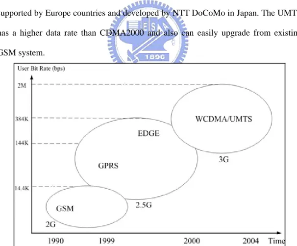
(15) 3G systems [16]. Figure 2.1 shows the evolution of communication system with time and user’s bit rate. 3G systems are generally expected to provide better system capacity and higher data rate up to 2M bps in the wireless communication system [5]. There are three main protocols supported by different vendors or countries. One of them is CDMA2000, which is adapted from CDMA One and pushed it into market by Qualcomm corp. in the USA. The advantage of CDMA2000 is to use the former CDMA One system ceasing the deployment cost of CDMA2000 and easily upgrade system from former system. Another one is TD-SCDMA that is mainly developed by China. Because mobile users are growing up enormously, the potential of TD-SCDMA may not be disregarded. The last one is WCDMA/UMTS, which is supported by Europe countries and developed by NTT DoCoMo in Japan. The UMTS has a higher data rate than CDMA2000 and also can easily upgrade from existing GSM system.. Figure 2.1 Evolutions from 2G to UMTS (3G) [5, 16]. 6.
(16) 2.1.2 A General UMTS Architecture The UMTS architecture could be divided into four conceptual parts [18], shown in Figure 2.2, there are four domains: 1) User Equipment (UE) 2) UMTS Terrestrial Radio Access Network (UTRAN) 3) Core Network (CN) 4) External Network. Figure 2.2 Conceptual UMTS Architecture [18] Using WCDMA radio access technique, end users can use diverse user equipments (UE) such as laptop, PDA or other mobile devices to connect with UTRAN, shown in part B in Figure 2.2, which is the same functional operation and called BTS (Base Transceiver System) in GSM as well as exchanging radio resources message with RNC (Radio Network Controller) which is called BSC (Base Station Center) in the GSM. Although roughly the same operation is performed between UTRAN and BSS (BTS plus BSC is called Base Station System), there are still some functional differences. For instance, BSC is not responsible for radio resource management. 7.
(17) (RRM) but RNC would take responsible for that instead. And then, through the Core Network (Fig 2.2 part C), UMTS data will be transmitted to PSTN, Internet or the other external network (Fig 2.2 part D). On the other hand, from the physical point of view, the general UMTS architecture can be split into several domains by the definition of 3GPP CN R5 [18] and which is considered about the highest-level group of physical entities, the basic architectural split is separated by the user equipment (terminals) and the infrastructure. (Figure 2.3) Therefore, it results in two domains: 1) User Equipment Domain and 2) Infrastructure Domain.[18] In general, an user equipment is the device to access UMTS services and it has a radio interface to the infrastructure domain. Furthermore, the user equipment is sub-divided into two sub domains: 1) the User Services Identity Module Domain (USIM) and 2) the Mobile Equipment Domain (ME). The USIM [19] contains data and procedures that provide user identification and enhance securely identification algorithm. These functions are typically embedded in a smart card, also called a 3G card. The mobile equipment domain performs the WCDMA radio transmission and contains the end-to-end application, for instance, laptop is connected to a mobile phone. Additionally, the Infrastructure Domain consists of two sub domains: 1) Access Network Domain (AN) and 2) Core Network Domain (CN). The Access Network Domain especially supports some functions to the access technique, such as WCDMA technique. Moreover, it consists of the physical entities, such as RNC, which manages the limited resources within the access network and provides a mechanism for users to connect to the next domain, Core Network Domain. The Core Network Domain describes in the next section.. 8.
(18) Home Network Domain [Zu] Cu. USIM Domain. Uu. Mobile Equipment Domain. Iu. Access Network Domain. (Serving Network Domain. [Yu]. Transit Network Domain. Core Network Domain. User Equipment Domain. Infrastructure Domain. Figure 2.3 UMTS domains [18] 2.1.3 Core Network Domain in UMTS The UMTS core network is based on the existing GSM core network switching system to enhance the functionality and capability. With such system architecture, UMTS systems can be backward system compatible with GSM.. For saving. upgraded cost and other business considerations, UMTS core network inherits some features from GSM to support 3G high speed network ability; it needs to add some new mechanisms to handle packet switching data flow. As shown in Figure 2.2, the core network is the interconnection domain between UTRAN and external network; it consists of some physical facilities to supports the voice and data communication services. Moreover, for stepping towards UMTS core network, the GPRS packet-based data service nodes, called SGSN (Serving GPRS Support Node) and GGSN (Gateway GPRS Support Note), will be added to upgrade the current GSM operation. Figure 2.4 shows the location of SGSN and GGSN. The SGSN takes charge of transmitting radio data from UTRAN into core network or inversely, it handles mobility management, authentication and security issues [5, 11]. In short, the 9.
(19) major job of SGSN is to provide packet routing.. Figure 2.4 SGSN in CN (R99) [20] Additionally, The GGSN plays a role as a common gateway between UMTS CN and an external network; it delivers packets form CN to the external network. GGSN also provides an IP dynamic allocation to mobile equipment, see the Fig 2.5.. Figure 2.5 GGSN in CN (R99) [20]. 10.
(20) From another viewpoint mentioned in the above section, the CN can be divided into three domains as Figure 2.6 shown. [18] z Serving Network (SN) domain: The serving network domain is mainly responsible for routing user information (packet switching or circuit switching). It has the ability to transport user specific data to Home Network domain or non user specific data to the Transit Network domain. z Home Network (HN) domain: The home network domain has the function to manage user’s subscription information, such as USIM, regardless of where the location of the users is. It contains user specific data permanently and is also responsible for handling home specific services, potentially not offered by the Serving Network domain. z Transit Network (TN) domain: The transit network domain is interconnection with core network domain and the external entities. However, if the remote party is located within the same network domain as the originating call, the functional entity of Transit Network would not be activated. Finally, the switching policy of core network is transformed into All-IP environment in the long run which integrates circuit switching and packet switching into one controller and has been illustrated in 3GPP R5[18]. As a result, involved with mobile IP and IPv6 technique, UMTS has a great opportunity to carry out seamless roaming between mobile network and fixed network environment, as well as more applications like VoIP, video conference or even online games can be implemented on the mobile devices properly.. 11.
(21) Figure 2.6 A Core Network Domain with HN, SN, TN [18]. 2.2 The QoS Classes QoS is an important issue for network applications. Generally speaking, the fundamental QoS required by a network application is to meet a set of performance requirements in a network [17]. There are many criteria to achieve QoS, some QoS attributes, such as: delay time, packet loss, jitter, and bit error rate (BER), are concerned in this study. There are more constraints in the mobile communication environment including the effect of radio links, movement and limitation of mobile devices. Therefore, the available bandwidth of mobile communication is valuable and a proper QoS scheme for mobile communication applications is required critically [11]. 2.2.1 Internet QoS Internet applications would base on the best–effort service since TCP/IP protocol 12.
(22) does not support the QoS concept. When bandwidth is available over Internet, packets of Internet application could be transmitted. There is no service quality for applications over Internet. Therefore, to solve the QoS issues of Internet applications, the IETF propose two schemes, IntServ and DiffServ, to try to support the QoS requirements of Internet applications. 2.2.1.1 IntServ The IETF working group on integrated services was formed in early 1990s and the main purpose of this group is focused on proposing a framework with per-flow QoS guarantee, a diagram is shown in Figure 2.7 [1, 22]. In addition to best-effort service, there are two service classes, such as: 1) Guaranteed service class: packets have a deterministic delay upper bound [22]. 2) Controlled load service class: an approximation of QoS from the unloaded network elements with the same flow [12]. It is treated as enhanced best-effort service. To implement IntServ, application traffics have to communicate their resource reservation requirements with network facilities (core router, edge router). Therefore, a signaling protocol, RSVP (Resource Reservation Protocol), which is also proposed by IETF attempts to meet this need. The sender sends a PATH message to the receiver. Along the transmission path, each router receives the PATH message to responds with a RESV message for this flow. With the upstream flow, every intermediate router has rights to adopt or decline the RESV message. If the request process is complete, the flow can retain the link bandwidth and buffer space. With RSVP protocol operating, IntServ scheme could be supported and Internet applications can receive their QoS. For IntServ scheme, routers play an important role. The functions of admission control routine, traffic policing, shaping, packet classifier and packet scheduler can be performed in the routers. Nevertheless, there are still shortcomings with IntServ. The main problem is the increasing amount of flow state information on the routers. 13.
(23) Therefore, it would result in the scalability issue.. Figure 2.7 IntServ and RSVP [22] 2.2.1.2 DiffServ To improve the drawbacks of IntServ, another QoS framework is proposed by IETF, it is called DiffServ. In contrast to IntServ, the DiffServ framework achieves simplicity and scalability. A DiffServ network is partitioned into different domains and each domain has a set of interior (core) routers and boundary (edge) routers. The DiffServ framework is shown in Figure 2.8. Edge routers would perform several functions, such as classifier, multifield classification (MF), behavior aggregate classification (BA), marker, meter, shaper and dropper. DiffServ defines a base set of packet forwarding treatments, named PHB (Per-Hop Behaviors). Several PHBs are defined by IETF: EF (Expedited Forwarding), AF (Assured Forwarding) and BE (Best Effort). As packets of Internet applications enter into a DiffServ domain, edge router would set the DSCP (DiffServ CodePoint) in each IP packet header according to applications’ service level agreements. With corresponding DSCP, packets would be forwarded with the corresponding PHB. Therefore, without providing per flow QoS, DiffServ uses per class QoS to operate more flexibly. When packets enter into one domain from another domain will be treated in a level of resource allocation called SLA (Service Level Agreement).. 14.
(24) Figure 2.8 A DiffServ Domain [11, 14] There are some studies proposed the relationship between the IETF PHBs and the four class UMTS applications. The mapping is shown in Table 2.1. Table 2.1 DiffServ class allocated to UMTS QoS class [11] UMTS OoS class. DiffServ Class. Conversational. EF. Streaming. AF12. Interactive. AF23. Background. AF33. 2.2.2 QoS in UMTS 3GPP has classified bearer services of UMTS into four QoS classes according to their delay sensitivity, jitter sensitivity and packet loss sensitivity, etc. These four classifications are [17]: 1) Conversational, 2) Streaming, 3) Interactive. 15.
(25) 4) Background. Applications like telephony speech, VoIP and video conference are classified into conversational QoS class. Conversational traffic class is highly sensitive to delay and jitter variation. Since the delay time is exceeded in 300ms, the perception of human would be ambiguous and feel uncomfortable when the voice is vibrated (jitter). Additionally, loss of packet is less concerned for a conversational application. For the streaming class applications, constant and stable flow rate is needed. Therefore, it is more sensitive to jitter than time delay. Packet loss is also most insensitive for a streaming application. The real time video or audio applications could be classified into this class. Comparing with streaming and conversational applications, the other two class applications, interactive and background, need more better error rate but less delay or jitter sensitive. Because interactive and background applications are likely to traditional data communication applications, the packet loss is controlled to ensure the accurate of data packets during transferred period. The main distinguishing factor between interactive and background QoS classes is mainly using interactive application in interactive class, such as interactive E-mail, interactive web browsing (WWW). Like interactive class, there are mainly using background applications in background QoS classes, and examples of background traffic class are background delivery of E-mails, transferring of files and SMS. The UMTS QoS architecture is defined as many sub-bearer services and each UMTS bearer service would be characterized by a number of quality and performance factor. Therefore, this study would aim at CN bearer service that is subset of UMTS bearer service, Figure 2.9.. 16.
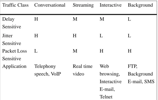
(26) Figure 2.9 UMTS OoS Architecture [17] Table 2.2 shows a mapping relationship among UMTS traffic classes, bearer service attributes and applications. Table 2.2 UMTS QoS Classes Attributes [17] Traffic Class. Conversational. Streaming. Interactive. Background. Delay Sensitive. H. M. M. L. Jitter Sensitive Packet Loss Sensitive Application. H. H. L. L. L. M. H. H. Telephony speech, VoIP. Real time video. Web browsing, Interactive E-mail, Telnet. FTP, Background E-mail, SMS. Note: H for high sensitive, M for medium sensitive L for low sensitive 17.
(27) 2.3 Queueing A queueing scheme is an important mechanism to allocate the limited network bandwidth to network applications. There exists an approaching relationship between QoS of applications and a queueing discipline operation. Particularly, network applications transmit their data in a packet switching mode and a queueing scheme operate in the gateways along the transmission path would decide which application’s packet should be forwarded early and which packet would be forwarded late. Therefore, the operations of a queueing scheme in a gateway would impact the QoS of network applications. How to implement a proper queueing scheme in a gateway would be an important issue for QoS of network applications. There are several queueing schemes have been proposed, let us have a review about them. 2.3.1 First Come First Serve (FCFS) The “first come first serve (FCFS)” is the simplest queueing scheme. The FCFS queueing scheme always exists in our daily life and people have much experience about it. In FCFS queueing scheme, every packets are stored in a single queue and be served depending on the order of arrival in the queue of the gateway. For network applications, the packets reach a gateway earlier, and then these packets could be forwarded to the next gateway earlier. The major limitation of FCFS is lack of flow isolation mechanism [12] and when a greedy flow served it would occupy the queue causing long delay time of the other flows. 2.3.2 Priority Queueing (PQ) The priority queueing scheme provides diverse treatments to relative flows and it often uses multiple queues to serve different priority. When packets reach a gateway, the PQ scheme would switch packets to the different priority queues according to the attributes of network applications. The packets in the higher priority queues could be 18.
(28) forwarded earlier than those packets in the lower priority queues. With the PQ scheme, applications with the different attributes or priorities would receive the differentiated service in the packet transmission. The PQ scheme could improve the shortcomings of the FCFS scheme and reduce the long delay time issue caused by the greedy applications. 2.3.3 Stochastic Fairness Queueing (SFQ) SFQ is one of fair queueing (FQ) scheme; it is also easy to implement. When packet of network applications enter into a gateway; SFQ would dispatch these packets into numbers of FIFO queues and forward these packets in FIFO queues using RR discipline. As named ‘’stochastic’’ fair queueing, SFQ would forward a packet in FCFS queues stochastically, not in a sequence, in each round. Bandwidth fairness between each flow is provided in this queueing scheme but it still has some limitations, such as large packets make long delay time, and it is less accurate to provide real fairness to meet the complicated network environment because of its simple queueing algorithm [10]. 2.3.4 Round Robin (RR) Round Robin queueing scheme uses circular concept to implement fairness among different queues. Basically, the queues are served in a RR mode; one packet would be forwarded from each queue in turn. This queueing scheme treats every queue in a good fairness when packet size of each application is fixed. But it would encounter a problem when packet sizes of applications are variable. Considering a possible situation, large size packets in a queue and small size packets in the others, there exists unfairness with RR queueing scheme; the applications with larger packet size get better transmission performance than applications with smaller packet size. In the 19.
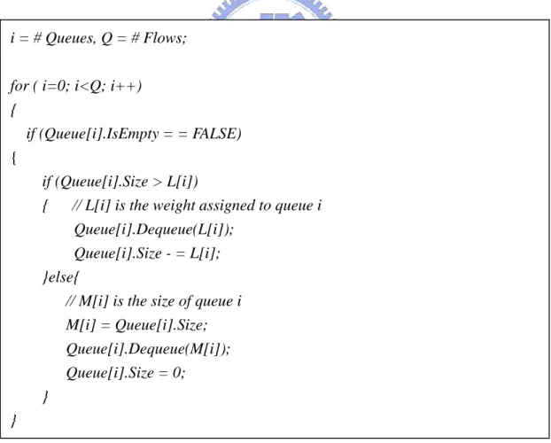
(29) above case, the RR queueing scheme only could achieve to forward packets fairly but bandwidth allocation might be unfair for applications. 2.3.5 Weighted Round Robin (WRR) Instead of serving one packet from one queue per round in RR queueing scheme, WRR queueing scheme modifies the mechanism to serve packets per round. WRR could serve n packets per round and the n would be calculated according to a ratio of relative queue bandwidth. Each flow would be specified a weighted value that corresponds to the calculated n value [12]. However, WRR is based on the RR queueing scheme. There are some limitations that WRR needs to know the (mean) packet size of applications and the waiting time for each queue in advance. Figure 2.10 shows the pseudo code of WRR. i = # Queues, Q = # Flows; for ( i=0; i<Q; i++) { if (Queue[i].IsEmpty = = FALSE) { if (Queue[i].Size > L[i]) { // L[i] is the weight assigned to queue i Queue[i].Dequeue(L[i]); Queue[i].Size - = L[i]; }else{ // M[i] is the size of queue i M[i] = Queue[i].Size; Queue[i].Dequeue(M[i]); Queue[i].Size = 0; } } Figure 2.10 A Pseudo Code of WRR. 20.
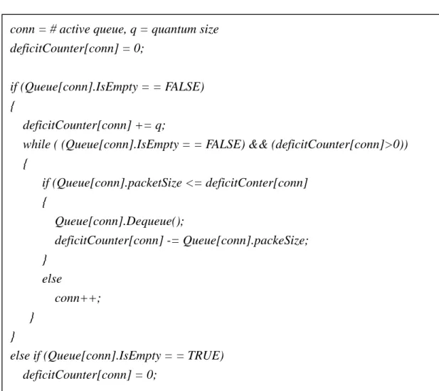
(30) 2.3.6 Deficit Round Robin (DRR) DRR [12] is proposed to improve the limitation of knowing the mean packet size of network applications. The procedure of DRR will be a variable value called quantum (q), which is initialized to represent the number of bits served in each queue. If the queue is not empty and the packet size is less or equal to the q value, the packet in this queue will be served in this round. Otherwise, it will not be served in this round. Then, a value called deficit counter would be initialized and increased by q. This DRR scheme makes an effective fairness with different packet sizes in one queue. The pseudo code is presented in Figure 2.11.. conn = # active queue, q = quantum size deficitCounter[conn] = 0; if (Queue[conn].IsEmpty = = FALSE) { deficitCounter[conn] += q; while ( (Queue[conn].IsEmpty = = FALSE) && (deficitCounter[conn]>0)) { if (Queue[conn].packetSize <= deficitConter[conn] { Queue[conn].Dequeue(); deficitCounter[conn] -= Queue[conn].packeSize; } else conn++; } } else if (Queue[conn].IsEmpty = = TRUE) deficitCounter[conn] = 0;. Figure 2.11 A Pseudo Code of DRR. 21.
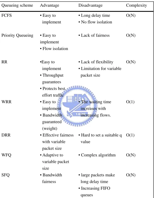
(31) 2.3.7 Weighted Fair Queueing (WFQ) WFQ is proposed to solve the variable size packets issue with a more complicated algorithm than DRR. It is based on Generalized Processor Sharing (GPS)[12] to deal with flows packet by packet and each packet would be assigned a tag (finish time) to determine which packet is delivered. The finish time is the time period that a packet in a flow will have been transferred and a packet with a lowest finish time will be sent. The finish time could be calculated by the following equation:. F(i, k, t) = max {F(i, k - 1, t), R(t)} + P(i, k, t) / Wi F(i, k, t) is the finish time of packet k in flow i that arrives at time t. R(t) is called a round number (virtual time), it is updated at each arrival and departure. Where R(0)=0 and R(t + τ ) = R(t) + τ / ∑ Wi ,. ∑ Wi. is sum of weights of active flows. P(i, k, t) is. the size of packet k that arrives in a flow i at time t. The pseudo code of WFQ is shown in Figure 2.12. Q = # queues // packet arrival for (i=0; i<Q; i++){ Queue[i].finish_time = virtual_time + pkt_size / queue[i].weight //packet extract min_finish_time = Min (Queue[i].finish_time) for (i=0; i<Q; i++) { packet_send(queue(i)) = Min (queue(i).finish_time) }. Figure 2.12 A Pseudo Code of WFQ 2.3.8 A Summary of Queueing Schemes Several queueing schemes have been discussed in the above sections. Each queueing scheme has its strength and weakness. With the different packet forward mechanism, each queueing scheme has its operation complexity and cost. A summary 22.
(32) of these queueing schemes are listed in Table 2.3. Table 2.3 Comparisons of Scheduling Queueing scheme. Advantage. Disadvantage. Complexity. FCFS. • Easy to implement. • Long delay time • No flow isolation. O(N). Priority Queueing. • Easy to implement • Flow isolation. • Lack of fairness. O(N). RR. •Easy to implement • Throughput guarantees • Protects best effort traffic • Easy to implement • Bandwidth guaranteed (weight) • Effective fairness with variable packet size • Adaptive to variable packet size • Bandwidth fairness. • Lack of flexibility • Limitation for variable packet size. O(N). • The waiting time increases with increasing flows.. O(1). WRR. DRR. WFQ. SFQ. • Hard to set a suitable q O(1) value • Complex algorithm. O(N). • large packets make long delay time • Increasing FIFO queues. O(N). 23.
(33) 3. A Preemptive Queueing Scheme for UMTS Background Traffic 3.1 System Overview 3.1.1 Basic Concept This study wants to aim at the UMTS background application to propose a queueing scheme. With the proposed queueing scheme, differentiated services could be supported among the background applications within an UMTS core network. An important or emergent background application could always receive a better transmission performance and QoS than other applications that might not be important or emergent. In this study, the proposed queueing scheme would preempt the bandwidth that allocated to the lower priority applications to the higher priority applications. With the preemptive queueing scheme operating, the proposed queueing scheme could provide the QoS for the important/emergent applications. In this study, the preemptive queueing scheme would base on the role of mobile network user to assign the different priority to the UMTS background applications. Therefore, the proposed preemptive queueing scheme is called the role based queueing (RBQ) scheme. With this role-based idea, UMTS users in different situation who need diverse service requirements; they can change their role of using mobile services on demands and received the required QoS provided by RBQ. Each predefined role will get a different level of priority. An UMTS user could pay cost to promote his role to get a higher priority for his UMTS background application. In this study, three type roles of UMTS users are defined, they are Emergency, VIP and Member. Emergency has the first priority; VIP has the second priority; and Member has the third priority. According to the defined roles in UMTS background. 24.
(34) applications, the different priority would be assigned to UMTS background applications. The RBQ would base on the priority to support the required QoS for UMTS background applications. 3.1.2 Assumptions Since UMTS is a sophisticated mobile communication system, there are some assumptions should be defined for the RBQ scheme to ensure effectiveness in this study. First, the RBQ scheme would be implemented in gateways within an UMTS core network. The operation domain of RBQ scheme is the UMTS core network. Second, an UMTS mobile network would support four type applications that defined by 3GPP. The RBQ scheme would provide differentiated services among UMTS background applications. There have been many researches discussing about QoS of delay-sensitive applications and this study would expect that non-delay-sensitive applications like e-mail or file transferring (non-voice application) can be overwhelmingly coming with 3G [21]. 3.1.2 UMTS QoS Criteria for RBQ 3GPP has defined the QoS attributes of UMTS bearer service that are the essential criteria to evaluate distinct traffic class [17]. The UMTS core network bearer service attributes are shown in Table 3.1. Since UMTS background application services cover all non-time critical applications such as E-mail, SMS, and FTP. The preemptive behavior among UMTS background seems allowable and can be manageable. Therefore, in the proposed queueing scheme, only background applications are chosen as the regulation targets. According to QoS bearer service attributes defined by 3GPP, the proposed RBQ scheme would follow those attributes to meet the QoS criteria required for UMTS background applications. Therefore, some core network bearer service attributes would be taken into consideration, such as maximum bitrate, 25.
(35) delivery order, maximum SDU (Service Data Unit) size, SDU error ratio, residual bit-error ratio, delivery of erroneous SDU and allocation/retention priority. Table 3.1 UMTS bearer QoS attributes defined for each traffic class [17] Traffic class. Conversational. Streaming. Interactive. Background. Maximum bitrate. X. X. X. X. Delivery order. X. X. X. X. Maximum SDU size. X. X. X. X. SDU Format information. X. X. SDU error ratio. X. X. X. X. Residual bit-error ratio. X. X. X. X. Delivery of erroneous SDUs. X. X. X. X. Transfer delay. X. X. Guaranteed bit rate. X. X. Traffic handling priority. X. Allocation/Retention priority. X. X. Sources statistics descriptor. X. X. Signaling indication. X. X. X. Why these seven core network bearer service attributes would be considered to evaluate the performance of the proposed RBQ scheme? The reasons are described as the following: • Maximum bitrate (kbps): It is a maximum number of bits that a UMTS bearer can deliver into service access point (SAP) in a specified interval. • Delivery order (y/n): This attributes determines whether the bearer sequences SDUs in the correct order. • Maximum SDU size (octets): 26.
(36) The maximum allowed SDU size in admission control and policing. • SDU error ratio: It is the fraction of SDUs. It is mainly used in UTRAN to configure protocols, algorithms, and error detection schemes. • Residual bit error ratio: It indicates the BER that is undetected. BER is specified for each subflow over the radio access bearer. • Delivery of erroneous SDUs (y/n/-): It indicates whether erroneous SDUs are delivered. • Allocation/Retention priority: It is used to discriminate between bearers when allocating or retaining scarce resources. After reviewing the definitions of core network bearer service attributes, this study selects the “bit rate”, “allocation/retention priority”’ and “max SDU size” bearer service attributes as the evaluation criteria for the RBQ scheme. Since the RBQ scheme would operate in the IP layer within an UMTS core network, other core network bearer service attributes about packet deliver sequence control and error control would be handled by the upper layer protocol, TCP. Therefore, those core network bearer service attributes should not be considered as the evaluation criteria for the RBQ scheme. These attributes include “delivery order”, “residual BER”, “delivery of erroneous SDU” and “SDU ratio”.. 3.2 RBQ Scheme 3.2.1 Queueing Scheme Architecture A queueing scheme can be divided logically into two parts, ENQUEUE and. 27.
(37) DEQUEUE. The ENQUEUE would process the arriving packets from the upstream gateway and the DEQUEUE would take care of the departing packets that should forward to the next downstream gateway. The architecture of RBQ scheme would be also divided into two parts, the ENQUEUE and DEQUEUE. Figure 3.1 shows the architecture of RBQ scheme. The detailed components of RBQ scheme will be described at the next section.. Figure 3.1 Role Based Queueing Scheme Architecture The ENQUEUE of RBQ scheme provides two functions, role selector and preemptive packet switcher. The role selector would examine the header of coming IP packet from the upstream gateway to identify a role that assigned to the packet. After examining the role identification of an IP packet, the role selector would base on the role identification to assign a QoS priority to the coming IP packet. Table 3.2 shows the mapping relationship between role identifications and QoS priority. After a QoS priority setting in an UMTS background application packet, the ENQUEUE preemptive packet switcher would be activated to handle the coming. 28.
(38) packets and enqueued packets into the logical queues. After a QoS priority setting in an Table 3.2 A mapping between role identification and QoS priority Priority Level. Role Identification. High. Emergency. Medium. VIP. Low. Member. UMTS background application packet, the preemptive packet switcher would depend on the QoS priority in the coming packet to enqueue the packet into the corresponding logical queue with the different QoS priority. The packets with the same QoS priority would be enqueued in the same logical queue. The logical queues for the different QoS priority are first-come-first-serve (FCFS) queues. Moreover, the preemptive packet switcher would perform a preemptive enqueue operation if the queue has no buffer size for a high QoS priority packet to enqueue the corresponding logical queue. The packet switcher would base on QoS priority of the arrival packet to determine whether the arrival packet would have the privilege to release a buffer size from a logical queue with a lower QoS priority. If there is an enqueued packet in the lower QoS priority logic queue, the tail packet would be removed to release a buffer size for the arrival packet with a higher QoS priority. Otherwise, the arrival packet would be dropped. With the preemptive enqueue operating, high QoS priority packets could always have privileges to enqueue the logic queues. The detailed description of ENQUEUE scheduling is presented at section 3.2.3. In the DEQUEUE part of BRQ scheme, a preemptive packet forwarder function is used to dequeue the packets form each logic queue. A round robin mechanism is adopted in the preemptive packet forwarder function. According to QoS priority 29.
(39) precedence, the packet forwarder function would forward the enqueued packets in the first QoS priority logic queue first. After finishing the packet forwarding in the first QoS priority logic queue, the packets in the second QoS priority logic queue would be forwarded. The packets in the third QoS priority logic queue would not be forwarded until there is no packet in the first QoS priority logic queue and the second QoS priority logic queue to be forwarded. With the preemptive packet forwarder function operating, the packets with high QoS priority always get precedence to be forwarded in the logical queue. Therefore, background applications with an emergent / important role could always receive better QoS. 3.2.2 The Logical Queue Operations in Role Based Queueing Scheme In the proposed RBQ scheme, there are three logical queues (LQ1, LQ2 and LQ3) to construct one physical queue (PQ), the RBQ. Each logical queue has its precedence QoS priority and would handle the different types of role-based packets. UMTS background application packets with the “member” role identification would be enqueued into the LQ1 which is the third QoS priority queue in the RBQ. Packets with the “vip” role identification would be enqueued into the LQ2 with the second QoS priority. Packets with the “emergency” role identification would be enqueued into the LQ3 with the first QoS priority. Figure 3.2 shows the logical queue in the RBQ.. 30.
(40) Figure 3.2 RBQ Elements Each of these three logical queues is a drop-tail queue (FIFO). The total buffer size of these three logic queues is equal to the buffer size of physical queue, i.e. LQ1 + LQ2 + LQ3 = PQ. In other words, when the buffer of physical queue (PQ) is full, the packet switcher function in RBQ scheme would be activated to execute a preemptive enqueue operation. The enqueued packet in the LQ1 or LQ2 would be removed to release the buffer space of PQ. Then, a packet with high QoS priority could be enqueued into the LQ3 or LQ2. With the RBQ scheme operating, the total buffer of physical queue is shared with each logical queue dynamically. Therefore, packets with the “emergency” or “vip” role identification could always be enqueued into the LQ3 or LQ2 logical queue. The buffer space of physical queue would be preempted by the packets with higher role identification. Table 3.3 shows the relationship among logical queues, relative packets types and priority.. 31.
(41) Table 3.3 Logical Queue Elements Logical Queue #. Scheduling. Role of packets. Priority. Discipline LQ3. Drop-tail. Emergency. High. LQ2. Drop-tail. VIP. Medium. LQ1. Drop-tail. Member. Low. 3.2.3 Preemptive Packet Switcher Function In the ENQUEUE part of RBQ scheme, the preemptive packet switcher function would switch the packets into the logical queue according to the QoS priority assign by the role selector function. If the buffer of physical queue is full, the preemptive packet enqueue operation would be activated by the preemptive packet switcher function to ensure the packet with high QoS priority could be enqueued into the corresponding logical queue. The process of ENQUEUE preemptive packet switchers is illustrated in Figure 3.3.. 32.
(42) Figure 3.3 ENQUEUE Preemptive Packet Switchers Process Diagram As a packet coming, the role selector function would base on the role identification in a packet to assign a value to variable K to the packet. The preemptive packet switcher would check whether the used physical queue buffer excess the maximum buffer size or not? If it does not excess the maximum buffer size, the preemptive packet switcher function would enqueue the packet into the corresponding logical queue. Otherwise, if there is no buffer space available to enqueue a packet into the corresponding logic queue, the preemptive packet switcher function would activate the preemptive packet enqueueing operation. First, the preemptive packet switcher function would check the QoS priority of a coming packet. If the QoS priority is lower, then the coming packet would be dropped. Otherwise, the preemptive packet switcher function would try to remove an enqueued packet from the tail of LQ1 or LQ2 to release the queue buffer space. If there is one packet removed from LQ1 or LQ2, then the coming packet would be enqueued into the corresponding logical queue. If no packet could be removed from LQ1 or LQ2, the coming packet would be 33.
(43) dropped. The preemptive packet switcher function always let packets with high QoS priority have a privilege to enqueue into the corresponding logical queue. The pseudo code of the preemptive packet switcher is shown in Figure 3.4.. K = role of packet, LQ = Logical Queue, PQ = Physical Queue if (Packets_k){ if (total LQ size > PQ size){ if (k=3){ if (LQ # 1 is not empty) remove packets from LQ #1 else if (LQ # 2 is not empty) remove packets from LQ #2 else drop Packets_k } else if (k=2){ if (LQ # 1 is not empty) remove packets from LQ #1 } else if (k=1) drop Packet_k } else{ allocate Packet_k into relative LQ enqueue Packet_k } } else Figure 3.4 Preemptive Packet Switcher Function Pseudo Code 3.2.4 Preemptive Packet Forwarder Function The DEQUEUE preemptive packet forwarder function uses round robin mechanism to forward packets from each logical queue in turn. According to the QoS. 34.
(44) priority precedence, the preemptive packet forwarder would forward the packets in LQ3 first. When there is no packet in LQ3, the packets in LQ2 would be forwarded. Finally, if there is no packet in LQ3 and LQ2, the packets in LQ3 could be forwarded. With the preemptive packet forwarder function operating in the RBQ scheme, the packets with higher QoS priority could be always forwarded first. The packets with lower QoS priority would not be forward until there is no higher QoS priority packet needs to be forwarded. Figure 3.5 is the diagram of DEQUEUE preemptive packet forwarder function.. Figure 3.5 Preemptive Packet Forwarder Function Diagram. 35.
(45) 4. Simulation Results Analysis 4.1 Simulation It is impossible to implement the proposed RBQ scheme in a real UMTS core network gateway to obverse the performance of RBQ scheme. Simulation is a possible way to understand the operations of the RBQ scheme. Several simulation scenarios are simulated to illustrate the operations of the RBQ scheme in an UMTS core network. With the different RBQ scheme simulation scenarios, some transmission performance of UMTS background applications with the different role identifications could be obtained. Some simulation results would be analyzed in this study. 4.1.1 Simulation platform The Network Simulator - ns (version 2.26) is used as the simulation tool. It is implemented on a PC based environment with an Intel pentium-III-1.3G CPU, 512MBytes RAM and a Linux RedHat 9 with kernel 2.4.x operating system. In order to simulate the RBQ scheme operations for background applications in an UMTS core network gateway, several C++ programs are coded to simulate UMTS background applications with different role identifications in ns2 simulator. Moreover, the RBQ scheme is implemented with a C++ program in ns2 simulator also. 4.1.2 Simulation topology The topology of simulation is the same as the simulation in the section 3.1 (see Figure 3.1). A number of TCP/UDP traffic flows are simulated to transmit packets from the S1 and S2 source nodes, all traffic flows have the same routing path and share the same bandwidth from N1 node to N4 node, then reach the D1 and D2 destination nodes. 36.
(46) The simulation topology is shown in Figure 4.1. There are three source nodes (S1 – S3) that are the senders of the UMTS background applications. Each source node would deliver packets of background application with different role identification to the corresponding destination (R1-R3). Two gateway nodes are implemented to set up a connection between the source nodes and destination nodes. The RBQ scheme is implemented in G1 gateway to regular the packets for UMTS background applications.. Figure 4.1 RBQS Simulation Topology 4.1.3 Simulation Scenario Several simulation scenarios are proposed to simulate the RBQ scheme operations in different operation situations. With these scenarios, this study tries to understand the performance of the RBQ scheme. The simulation scenarios are described as the following. z Scenario one: emergent event This scenario describes an assumption that when UMTS users are in an emergent situation and they must deliver e-mail or transfer files immediately with an UMTS 37.
(47) background application. In such situation, an “emergency” role identification should be assigned to the packets of this background application. For example, a journalist wants to use his UMTS mobile device to e-mail his emergent and the latest news back to newspaper office as soon as possible. z Scenario two: all-time overloaded traffic This scenario would assume that there exists a heavy UMTS application traffic load in a department stores or a celebration party. In this situation, there is no queue buffer in an UMTS core network gateway. No packet would be allowed to enqueue the queue in an UMTS core network gateway. For example, people want to send SMS to each other to celebrate the New Year is coming in the Eve of New Year but the UMTS network system is overloaded and could not deliver the SMS for UMTS users at the time. In this simulation scenario, all background applications with different role identifications would keep sending packets during the 10 seconds simulation period. 4.1.4 Bandwidth settings Since UMTS available bandwidth would depend on the moving speed of an UMTS user [11, 17], several bandwidth settings, such as 2Mb, 384Kb, 144Kb, are simulated between the two gateways (G1-G2). The bandwidth settings are listed in Table 4.1: Table 4.1 Flow Bandwidth Configuration Table Emergency. VIP. Member. A1 A2 B1 B2. 0.3 Mb 1.0 Mb 84 Kb 70 Kb. 1.0 Mb 3.0 Mb 90 Kb 200 Kb. 0.7 Mb 2.0 Mb 200 Kb 180 Kb. Sum of flow bandwidth 2.0 Mb 6.0 Mb 374 Kb 450 Kb. C1 C2. 10 Kb 14 Kb. 30 Kb 100 Kb. 20 Kb 160 Kb. 60 Kb 274 Kb. (3) (2). (1). 2Mb 384Kb 144Kb. Note: (1) Total bandwidth of gateway, (2) Sets of simulation, (3) Traffic type. 38.
(48) 4.2 Simulation result analysis 4.2.1 Definitions of Throughput and Packet Drop Rate According to the proposed scenarios, several simulations were executed with ns2 simulator and several groups of data were also collected from the trace files generated by the ns2. This study tries to use throughput and packet drop rate as the evaluation criteria to the RBQ scheme. In order to understand the performance of RBQ scheme, this study codes several string process programs with UNIX awk utility to process the data in the trace files and get the information about the transmission throughput and packet drop rate that could be used to evaluate the performance of RBQ scheme. About the two evaluation criteria, throughput and packet drop rate, their definitions in this study are described as the following. z Throughput: It is defined as numbers of packets which are received by the destination from the source within a given time interval T. This study would calculate total numbers of packets from G1 to G2 except removed packets by the RBQ scheme in gateway G1 during a period of time. The calculation formula of throughput is shown as the following. T. Throughput tp = ∑ [(# packets _ enqueue) p − (# packet _ remove) p ]t t =1. Throughput tp is noted for throughput of traffic type p with a time interval T. z Packet drop rate:. It is defined as the ratio of dropped packets number to total sent packet number during a period of time T. The calculation formula of packet drop rate is shown as the following. T. (# packet _ drop ) p. t =1. (# all _ packet _ enqueue) p. Packetdropratetp = ∑ [. 39. ]t.
(49) 4.2.2 Throughput and Packet Drop Rate among the Simulated Background Applications. Several groups of simulation data are collected from ns2 simulator. This study would base on the different scenarios to do some analyses. With these analyses, this study tries to understand the performance of the proposed RBQ scheme. Several analyses are shown in the following sections. 4.2.2.1 Indoor or Slow Speed Move. This study wants to know the performance of RBQ scheme when UMTS users are indoors or move slowly. One scenario would assume the total required bandwidth of the three background applications is equal to the bandwidth over the G1-G2 link. Therefore, there would not traffic congestion occur.. Figure 4.2 Background Applications’ Throughput as They Require 2MB Bandwidth Figure 4.2 shows the all background applications have 2MB bandwidth and the throughput of VIP application is always higher than MMB and EMR. Because the throughout of VIP application is higher than MMB and EMR. Moreover, the total flow bandwidth is not greater than gateway bandwidth (2MB). Therefore, all packets of these three background applications can be delivered smoothly without being. 40.
(50) removed or dropped during the simulation time. The RBQ scheme would let all applications’ packets be delivered from senders to receivers smoothly when the total required bandwidth is less than the bandwidth between G1 and G2. Another scenario assumes the total required bandwidth of the three background applications is more than the bandwidth over the G1-G2 link. In this situation, traffic congestion would occur between the G1-G2 link. Figure 4.3 shows the throughput of the three background applications.. Figure 4.3 Background Applications’ Throughput as They Require 6MB Bandwidth Comparing with Figure 4.2, the throughput of MMB application keeps a steady status; only 40 packets were transmitted during the 10 seconds. Observing these simulation results, this study finds when the total bandwidth (2MB) over the G1-G2 link is less than total flow bandwidth (6MB). In such a heavy traffic situation, the RBQ scheme executes a packet preemptive operation among these UMTS background applications. The MMB application’s enqueued packets would always be removed when there is no queue buffer space in gateway G1. Since the MMB application has the lowest priority among these three background applications. Additionally, there exists an interesting result. The required bandwidth (3MB) of the VIP application is 41.
(51) higher than the required bandwidth of the EMR application (1Mb). Although the QoS profile priority of the EMR application is higher than the VIP application, the RBQ scheme would depend on the arrival packet ratio of each application to allocate a queue buffer to each application. Therefore, VIP application’s throughput is higher than EMR application. When the required bandwidths of the applications exceed the bandwidth over the G1-G2 link, the packet of the applications might be removed or dropped by the RBQ scheme. Figure 4.4 shows the packet drop rate of these three background applications when their required bandwidths are 6MB. The packet drop rate of MMB application keeps increasing quickly from the 5th second (7.08 %) to the 10th second (24.96%). By looking into the MMB logic queue and the physical queue, there is no buffer space to enqueue a MMB application packet since the 5th second. This shows the RBQ scheme would remove an enqueued packet from a lower QoS profile priority logic queue to let a packet with a higher QoS profile priority enqueue into its logic queue. This packet preemptive operation could always keep a higher QoS profile priority packet enqueue into its logic queue. Therefore, EMR and VIP application always get better throughput than MMB application.. Figure 4.4 Background Applications’ Packet Drop Rate as They Require 6MB 42.
(52) Bandwidth 4.2.2.2 Fast Speed Move. When UMTS users are moving in a fast speed, only 384KB bandwidth can be afforded by UMTS system for UMTS users. This study tries to understand the performance of the RBQ scheme when UMTS users move in high speed. One scenario is based on 384KB bandwidth over the G1-G2 link. The required bandwidth of these three background applications is 374KB. The required bandwidth is less than the bandwidth afforded by UMTS system. The simulation results are shown in Figure 4.5. All packet of these three background applications were delivered smoothly from the source nodes to the destinations nodes. Examining the ns2 simulation trace file, there is no packet to be removed from the G1 queue buffer or be dropped. The throughputs of these applications are based on the ratio of their required bandwidth. Therefore, MMB application gets the first throughput; VIP application gets the second throughput; and EMR application gets the third throughput.. Figure 4.5 Background Applications’ Throughput as They Require 374KB Bandwidth As UMTS user move in a fast speed, another scenario assumes the total required. 43.
(53) bandwidth (450KB) of these three background applications is more than the afforded bandwidth (384KB) over the G1-G2 link. According to the ratio of required bandwidth, these three applications get their throughputs. The simulation results are shown in Figure 4.6.. Figure 4.6 Background Applications’ Throughput as They Require 450KB Bandwidth Since the required bandwidth exceeding the afforded bandwidth, the packet preemptive operation of the RBQ scheme was activated during the simulation. By examining the simulation log, the enqueued packets of MMB were removed from the tail of MMB logic queue. Moreover, the coming packets also were dropped at the 7th second.. 44.
(54) Figure 4.7 Background Applications’ Packet Drop Rate as They Require 450KB Bandwidth 4.2.2.3 High Speed Move. As UMTS users are moving in a high speed, UMTS system only provides 144KB bandwidth to UMTS users. In this study, several scenarios base on that UMTS user move in a high speed, the bandwidth over the G1-G2 link is 144KB, and the required bandwidth of these three applications. One scenario is that the required bandwidth (60KB) of these three applications does not exceed the bandwidth (144KB) afforded by the G1-G2 link. The simulation result is shown in Figure 4.8. Each packet of these three applications is delivered smoothly from the senders to the receivers. No packet is removed or dropped. The throughputs of these threes applications also base on the ratio of their required bandwidths.. 45.
(55) Figure 4.8 Background Applications’ Throughput as They Require 60KB Bandwidth Another scenario is that the required bandwidth (274KB) of these three applications exceeds the bandwidth (144KB) afforded by the G1-G2 link. Figure 4.9 shows the simulation result. Since the bandwidth over the G1-G2 link cannot support the required bandwidth of these three applications; the RBQ scheme is activated to execute the packet preemptive operation. It is obvious that throughput of MMB application downgrade at the 4th second. Figure 4.10 also shows packet drop rate of these three applications. Since there is a heavy traffic load over the G1-G2 link, the RBQ scheme always removes the enqueued packets or dropped since the third second. Due to the QoS profile priorities of EMR and VIP applications are higher than MMB application, there is no packet of EMR or VIP application removed or dropped.. 46.
(56) Figure 4.9 Background Applications’ Throughput as They Require 274KB Bandwidth. Figure 4.10 Background Applications’ Packet Drop Rate as They Require 274KB Bandwidth. 47.
(57) 5. Conclusion 3G communication would be a trend in a mobile communication environment and it is coming overwhelmingly. However, there are many mobile communication applications over 3G mobile communication systems, the limited bandwidth provided by 3G would become shortage in the future. Therefore, effective mechanisms are required to solve these issues of 3G communication adequately. In this study, a preemptive scheduling scheme, RBQ, is proposed. The RBQ system is aimed at 3G background applications and its operations domain is within 3G UMTS core network. The proposed RBQ scheme assigns the transmission priorities based on users’ roles. Three users’ roles are defined; they are EMR, VIP and MMB. According to the assigned priorities, differentiated services are supported among 3G mobile applications. The RBQ scheme would execute a preemptive operation while the bandwidth required by applications excess the total available bandwidth in an UMTS core network gateway. The RBQ scheme would remove or drop a lower priority packet from the logic queueing to release the queueing space to enqueue a higher priority packet. In this study, several scenarios are simulated to understand the performance of the RBQ scheme. The throughput and drop rate of background applications are used as indicators to evaluate the performance of the RBQ scheme. As the simulated results show the RBQ scheme executes an effective packet preemptive operation in an UMTS core network gateway to support differentiated services among background applications. In the future work, some researches could apply the results of this study to do a further research, such as: the integration of the RBQ scheme and the 3G billing system. To implement the concept of RBQ scheme in UMTS billing, it would assist 48.
(58) UMTS system operators to provide more adaptive services and enhance their revenues.. 49.
數據
![Figure 2.2 Conceptual UMTS Architecture [18]](https://thumb-ap.123doks.com/thumbv2/9libinfo/7978212.158908/16.892.137.762.392.755/figure-conceptual-umts-architecture.webp)
![Figure 2.4 SGSN in CN (R99) [20]](https://thumb-ap.123doks.com/thumbv2/9libinfo/7978212.158908/19.892.173.724.149.517/figure-sgsn-in-cn-r.webp)
![Figure 2.6 A Core Network Domain with HN, SN, TN [18]](https://thumb-ap.123doks.com/thumbv2/9libinfo/7978212.158908/21.892.202.693.111.571/figure-core-network-domain-hn-sn-tn.webp)
+7
![Figure 2.7 IntServ and RSVP [22] 2.2.1.2 DiffServ](https://thumb-ap.123doks.com/thumbv2/9libinfo/7978212.158908/23.892.151.782.150.386/figure-intserv-and-rsvp-diffserv.webp)
![Table 2.1 DiffServ class allocated to UMTS QoS class [11] UMTS OoS class DiffServ Class](https://thumb-ap.123doks.com/thumbv2/9libinfo/7978212.158908/24.892.235.662.544.786/table-diffserv-class-allocated-umts-class-diffserv-class.webp)
相關文件
2.1.1 The pre-primary educator must have specialised knowledge about the characteristics of child development before they can be responsive to the needs of children, set
Reading Task 6: Genre Structure and Language Features. • Now let’s look at how language features (e.g. sentence patterns) are connected to the structure
Promote project learning, mathematical modeling, and problem-based learning to strengthen the ability to integrate and apply knowledge and skills, and make. calculated
Now, nearly all of the current flows through wire S since it has a much lower resistance than the light bulb. The light bulb does not glow because the current flowing through it
volume suppressed mass: (TeV) 2 /M P ∼ 10 −4 eV → mm range can be experimentally tested for any number of extra dimensions - Light U(1) gauge bosons: no derivative couplings. =>
According to the Heisenberg uncertainty principle, if the observed region has size L, an estimate of an individual Fourier mode with wavevector q will be a weighted average of
• Formation of massive primordial stars as origin of objects in the early universe. • Supernova explosions might be visible to the most
This kind of algorithm has also been a powerful tool for solving many other optimization problems, including symmetric cone complementarity problems [15, 16, 20–22], symmetric
