國
立
交
通
大
學
多媒體工程研究所
碩
士
論
文
由三維動物模型產生
V 型摺疊立體卡片之研究
V-fold Animal Pop-up Card Generation from 3D Models
研 究 生:胡詠寧
指導教授:施仁忠 教授
魏德樂 教授
由三維動物模型產生 V 型摺疊立體卡片之研究
V-fold Animal Pop-up Card Generation from 3D Models
研 究 生:胡詠寧 Student:Yung-Ning Hu
指導教授:施仁忠 Advisor:Prof. Zen-Chung Shih
魏德樂
Prof. Der-lor Way
國 立 交 通 大 學
多 媒 體 工 程 研 究 所
碩 士 論 文
A Thesis
Submitted to Institute of MultimediaEngineering College of Computer Science
National Chiao Tung University in partial Fulfillment of the Requirements
for the Degree of Master
in
Multimedia Engineering
August 2012
Hsinchu, Taiwan, Republic of China
I
由三維動物模型產生
V 型摺疊立體卡片之研究
研究生:胡詠寧 指導教授:施仁忠教授
魏德樂教授
國立交通大學多媒體工程研究所
摘 要
立體卡片為紙張藝術的一種,泛指在頁面中加入可動機關或立體紙藝的卡片,而 立體書則是由多個立體卡片組合而成的書籍。此種藉由展開來彈出各式各樣立體結構 的藝術作品,無論是大人或小孩都十分喜愛。然而立體卡片的設計與製作並非相當容 易,為了使卡片完美順暢地開闔,需要豐富的經驗,即使是熟練的專家也要透過不斷 地嘗試錯誤才能設計出構造複雜的立體書或是立體卡片。 立體卡片的種類相當多,本篇論文利用三維動物模型來產生 V 型摺疊的立體卡片。 藉由觀察模型的特徵並歸納出數種類型,擷取模型各部位的輪廓作為立體卡片中元件 的形狀,組合成立體卡片。在產生元件的過程中,為了使結果能符合立體卡片的各項 性質,也必須考慮到各個元件之間的關係。另外,本篇論文也實作了模擬立體卡片成 品開闔的動畫,讓使用者能夠觀看卡片展開的效果。
II
V-fold Animal Pop-up Card Generation from 3D Models
Student: Yong-Ning Hu Advisor: Prof. Zen-Chung Shih
Prof. Der-Lor Way
Institute of Multimedia Engineering
National Chiao-Tung University
ABSTRACT
Pop-up is an interesting form of paper art which fascinate children and adults. It is fun to look 3D shapes jump up from the page, and these shapes can be stored in the pages flat when the card is closed. However, manual design of pop-ups is not an easy task. It needs lots of experience to make the pop-up open and close perfectly. Even for proficient masters, it would take a lot of time to complete a pop-up design. In this thesis, we focus on a common class of pop-ups which is called v-fold pop-ups. We introduce different types of animal pop-ups and propose an algorithm to create v-fold pop-ups from 3D animal models. In our system, we find the representative contour of every part from a segmented model, and then use the contour as the shape of the pop-up piece. We compose them together to generate a pop-up card. Additionally, we implement the simulation of the pieces popping up as it is opened. This pop-up animation enables the designer observe the pop-up card before making it manually.
III
Acknowledgements
First of all, I would like to express my sincere gratitude to my advisors, Prof. Zen-Chung Shih and Prof. Der-Lor Way for their guidance and patience. Without their encouragement, I would not complete this thesis. Thanks also to all the members in Computer Graphics and Virtual Reality Laboratory for their reinforcement and suggestion. I want to thank to all the people who ever supported me during these days. Finally, I will sincerely dedicate this thesis to my family.
IV
Contents
ABSTRACT (in Chinese) ………..I ABSTRACT (in English) ……….II ACKNOWLEDGEMENTS ………III CONTENTS ………IV LIST OF FIGURES ………...V LIST OF TABLES ………VII
CHAPTER 1 Introduction ………1
CHAPTER 2 Related Works ………3
2.1 Paper Crafting ……….3
2.2 Computational Pop-ups ………4
2.3 Planar Shape Abstraction ………5
CHAPTER 3 Background ………6 3.1 History ………..6 3.2 Pop-up Mechanisms ………7 CHAPTER 4 Algorithm ………11 4.1 Scaffold ………11 4.2 V-fold Digraph ………12 4.3 Animal Scaffold ………15 4.4 Pop-up Generation ………19
4.4.1 Mesh Segmentation and Labeling ………20
4.4.2 2D Feature Shape Extraction ………20
4.4.3 2D Feature Shape Attachment ………22
4.5 Pop-up Simulation ………25
CHAPTER 5 Experimental Results ………29
CHAPTER 6 Conclusion and Future Work ………...35
V
List of Figures
Figure 2.1: V-style pop-up [15]. (a) A v-style pop-up in fully opened state. (b) The Eiffel
Tower pop-up constructed by automated algorithm. ………5
Figure 3.1: “Alice Adventures in Wonderland” by Robert Sabuda ………7
Figure 3.2: Pop-up cards designed by Robert Sabuda for DIY ………7
Figure 3.3: A simple pop-up. ………8
Figure 3.4: A complex pop-up. ………8
Figure 3.5: (a) The pop-up opened through 180°. (b) The angles in a closed pop-up. ……9
Figure 3.6: The pop-up pieces are fully stretched. ……….9
Figure 4.1: Scaffold. ………11
Figure 4.2: The axes and angles in an element. ………12
Figure 4.3: A v-fold pop-up and its v-fold digraph. ………13
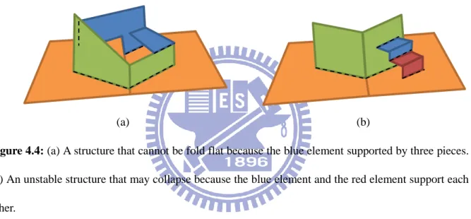
Figure 4.4: (a) A structure that cannot be fold flat because the blue element supported by three pieces. (b) An unstable structure that may collapse because the blue element and the red element support each other. ………14
Figure 4.5: (a) The v-fold graph of head type. (b) The prototype of head type. …………16
Figure 4.6: (a) The v-fold graph of bust type. (b) The prototype of bust type. ………….17
Figure 4.7: (a) The v-fold graph of bird type. (b) The prototype of bird type. ………18
Figure 4.8: The processing flow of pop-up generation. ………19
Figure 4.9: The head of pig model and its projection result. The blue points indicate projected points from mesh vertices. The black points mean sample points in red check region. Left: the point on the contour. Right: the point not on the contour. ………21
Figure 4.10: Left: A polygon and its goal plane. Right: Viewed from above. ………22
Figure 4.11: The piece cut by a cutting plane. ………23
Figure 4.12: Before and after cutting process. ………23
Figure 4.13: The axes and angles in an element of a simple pop-up. ……….25
Figure 4.14: The axes in a complex pop-up. ………26
Figure 4.15: Find axis Z by given X, Y, α, and β. ……….27
Figure 4.16: A v-fold pop-up in deferent fold angles. ………28
Figure 5.1: Top: The input model and segmentation. Middle: Result of pop-up with head type. Bottom: Pop-up simulation. ………30
Figure 5.2: Top: The input model and segmentation. Middle: Result of pop-up with bust type. Bottom: Pop-up simulation. ………31
Figure 5.3: Top: The input model and segmentation. Middle: Result of pop-up with bird type. Bottom: Pop-up simulation. ……….32
Figure 5.4: Donkey in head type and bust type, wolf in bust type and pig in bust type. ………33
VI
VII
List of Tables
Table 4.1: Cutting lists of the head type scaffolds. ………24 Table 4.2: Cutting lists of the bust type scaffolds. ………24 Table 4.3: Cutting lists of the bird type scaffolds. ………25
1
CHAPTER 1
Introduction
People usually invite their friends to a party or give wishes in anniversaries by sending cards. Recently, many paper cards become more exquisite and creative. Pop-up card is one of popular paper cards. When it is opened, the paper architecture will form a 3D lively scene. Making a pop-up card by self is fun but not easy. When designer has an idea, he needs to think how to accomplish it. Most time of design a pop-up card is spending on trial and error. When it looks a little bit wrong, there is nothing to do except cut a new piece, glue it in, and see how that looks. This is a tedious process. It will be more facile if there is a convenience tool for help us to design a pop-up card.
Unlike man-made objects, organic objects have various features. Since a v-fold pop-up card is organized by planar pieces, the shapes of the pieces are significant for express the features of an object. In this thesis, we observe animal pop-ups made by artists and generalize three common types of pop-up prototype. The proposed method extracts typical contours from an animal 3D model, and creates pop-up pieces based on the contours. These pieces will be attached to the defined pop-up structure, and finally constructed an animal pop-up card. Accordingly, users can easily create a pop-up card from an animal 3D model.
The main contributions of this thesis are as follow: (1) we present a data structure for the v-fold pop-up; (2) a novel algorithm is applied for generating a pop-up card from a 3D
2
animal model. The data structure is called v-fold digraph to construct pop-up cards. The properties of v-fold digraph ensure the stability of the pop-up structure. Then we observe the animal pop-up card made by artists and generalize three types of structures. With these structures, a few planar pieces were used to represent a 3D model and preserve its features. In order to show the results, we simulate the animation of a pop-up card (see chapter 4.5). Finally, all experimental results were constructed to real-paper pop-up cards. Furthermore, users can observe the pop-up card in every angle during it is opened and closed from the pop-up simulation.
In our system, User could input a 3D mesh first. Then, the mesh is segmented to several parts and labeled, moreover, labels are used for tag the parts of the mesh as “HEAD”, “EAR”, etc. After segmentation and labeling, a pop-up element was generated iteratively. During the processing iteration, an element was chosen in the pre-defined v-fold diagraph that is not added to current structure yet. And then we extract the contour of the corresponding part from the model. The contour was used as the shape of pop-up piece and was attached on the current scaffold. Finally, these pieces construct a pop-up geometry. User can adjust the position of the patches in the pop-up card, observe the pop-up animation, and then make a true pop-up card.
This thesis is organized as follows: In chapter 2, we review the related works about paper crafting, computational pop-ups, and shape abstraction. In chapter 3, we introduce the history and the background knowledge of pop-ups. In chapter 4, we present the data structure of pop-ups, the approach for generating a pop-up, and the algorithm for pop-up simulation. The results from our system are shown in chapter 5 and the conclusion and future work are discussed in chapter 6.
3
CHAPTER 2
Related Works
2.1 Paper Crafting
Origami is the art of paper folding originated from Japan. The purpose of this art is to transform a flat sheet of paper into a sculpture through folding and sculpting techniques. Unlike pop-ups, the uses of cuts or glue are not considered to be origami. The main topic in origami is folding and foldability, which has been studied in the literature [9], [4], [23]. Tachi introduced a method for automatically generating arbitrary polyhedral surfaces [25]. Kikian proposed an algorithm for generating curved folding that is much more restricted then conventional origami [12].
Paper models, also called card models or papercraft, are models constructed from sheets of paper. Mitani proposed a scheme for producing unfolded papercraft patterns of animal from triangulated meshes by strip-based approximation [20]. His work was followed by several interesting extensions, which approximate the shape of 3D mesh using a few types of surfaces [24] [16]. Takahashi presented an approach to unfolding triangular meshes without any shape distortions; this approach is inspired by the concept of topological surgery [26].
Paper architecture is a type of pop-up that is made from a sheet of paper by cutting and folding. A class of paper architecture is called parallel paper architecture. The patches in
4
parallel paper architecture maintain parallel to the two exterior pages during opening and closing. This simple mechanism enabled development of studies that construct paper architecture from a 3D model [21] [14] and interactive design tools [19].
2.2 Computational Pop-ups
The computational studies on pop-ups are focus on a few known mechanisms, such as v-fold, lattice-type fold, and cube-type fold. Lee et al. [13] and Glassner [5] studied the structure of v-fold pop-ups and presented formulas for simulating a pop-up. Mitani et al. presented a method to design a lattice-type pop-up that consists of pieces of paper [18]. Each piece has slits for assembling and is figured as the cross section of a 3D model. Okamura et al. [22] developed an interface for assisting the design of pop-up. The pop-up consist of tent, box, and cube mechanisms. These studies have been applied to interactive design systems that enable designer build pop-ups on computer. Recently, Li [15] presented a geometric study of v-style pop-ups, which has more restrictions than v-fold pop-ups and consist of patches that have four orientations shown as figure 2.1 (a). Li also developed an interactive tool for designing v-style pop-ups by a few mechanisms.
Because of that determining the foldability of a pop-up is a NP-hard problem [27], there are little research about generate pop-ups automatically. Hara and Sugihara [7] presented an algorithm to construct a two-dimensional v-fold pop-up automatically with any given polygon, in this type, all folding lines are parallel. Li [15] proposed a voxel-based algorithm to generate a v-style pop-up from a voxelized model. Their manner is appropriate for man-made objects, such as architectures. Figure 2.1 (b) demonstrates a result from this automated algorithm. The algorithm approximated the input model by many pieces, so it is hard to make a true pop-up card manually. In contrast, the goal of this thesis is express the
5
animal models by a few pieces without losing their characteristics. The users can make the pop-up card by hand easily.
(a) (b)
Figure 2.1: V-style pop-up [15]. (a) A v-style pop-up in fully opened state. (b) The Eiffel Tower
pop-up constructed by automated algorithm.
2.3 Planar Shape Abstraction
Planar shape abstraction addresses the problem of finding planes as a good proxy for a 3D shape. McCrae et al. [17] proposed an approach for generating shape proxies based on principles inferred from user studies. Such proxies are often used for extreme simplification leading to billboard clouds [3] and impostors for lightweight rendering [11]. The other application is paper statues and puppets that can be physically constructed from cardboard [8]. A paper statue is made by sliding the planes together with slits at their intersections. In this work, principal component analysis (PCA) is adapted for deriving appropriate planes.
6
CHAPTER 3
Background
3.1 History
Movable book is a form of books that has movable devices or paper sculpture in pages. The audiences for early movable books were adults, not children. Allegedly, the first movable book appeared in 14th century Europe, Ramon Llull used a revolving disc to illustrate his theories in astrological book. In the following centuries, various techniques have been developed but they were always used in scholarly works.
Until 18th century, these techniques were applied to books that designed for entertainment, particularly for children. The first real pop-up books were produced by Ernest Nister and Lothar Meggendorfer. These books were popular in Germany and Britain during 19th century. In the United States, Harold Lentz produced pop-up books that included classic fairy tales and Disney stories. He was the first publisher to use the term “pop-up” to describe their movable illustrations.
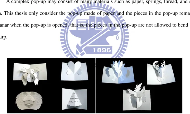
Today’s pop-up books continue to fascinate audiences worldwide. Many famous stories and movies were used as the pop-up subjects by artists, such like Robert Sabuda, David Carter and Matthew Reinhart. Some pop-ups designed by Sabuda are shown as figure 3.1 and 3.2.
7
Figure 3.1: “Alice Adventures in Wonderland” by Robert Sabuda
3.2 Pop-up Mechanisms
A complex pop-up may consist of many materials such as paper, springs, thread, and so on. This thesis only consider the pop-up made of paper and the pieces in the pop-up remain planar when the pop-up is opened, that is, the pieces in the pop-up are not allowed to bend or warp.
Figure 3.2: Pop-up cards designed by Robert Sabuda for DIY
A v-fold is a rigid pop-up consists of elements that each element has two planar pieces and records two supporting pieces. Our work is to construct this type of pop-ups like figure 3.2. A simple v-fold pop-up is shown in figure 3.3, it is constructed by two supporting pieces and two pop-up pieces. To build a more complex pop-up, it needs add an element that has two
8
new pieces and specifies two existed pieces as supporting pieces. That means the existed pieces support the new pieces. For example, the pieces of level 2 in figure 3.4 are supported by a level 1 piece and a level 0 piece.
Figure 3.3: A simple pop-up.
For a general pop-up, there are some geometric properties described in Li [15]. They are called foldable, stable, intersection-free, and enclosure that defined as fallows separately: 1. The pop-up can be closed to a flat surface and opened again without destroying its
construction.
2. The closing and opening of the pop-up do not need extra forces except holding and turning the two exterior pages.
3. The pieces in the pop-up do not intersect during closing and opening. 4. When the pop-up is closed, all pieces are enclosed within the exterior pages.
Figure 3.4: A complex pop-up.
Pop-up Piece Left Page Right Page Level 1 Level 0 Level 2 Level 3
9
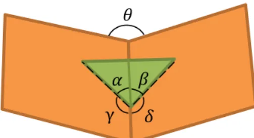
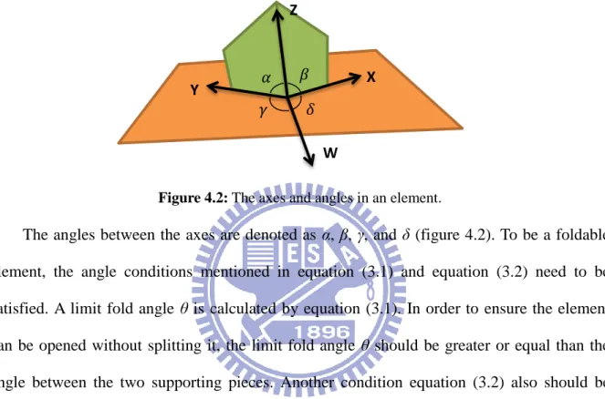
To be a foldable pop-up, it needs to satisfy the angle conditions that have been studied in literature [6] [13] [15]. The folding lines in a simple pop-up must be either all parallel or all concurrent. This thesis only considers the situation that all folding lines converge on a point. The parallel state was approximated by a very far convergent point. When the folding lines converge on one point, there are four angles between the folding lines that are denoted as α, β, γ and δ (see figure 3.5 (a)). Note that γ and δ are obtuse angles. Since the pieces are rigid, the angles are fixed during the opening and closing of pop-up. The four angles decide a limit angle θ that the pop-up pieces are fully stretched. Therefore, the pop-up pieces fall into the same plane (see figure 3.6). The relation of the limit fold angle θ and the angles between the folding lines is:
cos 𝜃 = [cos( 𝛼 + 𝛽) − cos 𝛾 cos 𝛿]/(sin 𝛾 sin 𝛿). (3.1)
(a) (b)
Figure 3.5: (a) The pop-up opened through 180°. (b) The angles in a closed pop-up.
Figure 3.6: The pop-up pieces are fully stretched.
𝛼 𝛽 γ 𝛿 𝜃 𝛼 𝛽 γ 𝛿 𝜃 𝛾 − 𝛼 𝛽 𝛼 𝛿 − 𝛽
10
When the pop-up is fully closed, the pop-up pieces must lie flat between the exterior pages. Figure 3.5 (b) illustrates that in closed situation:
𝛾 − 𝛼 = 𝛿 − 𝛽 > 0. (3.2) Figure 3.4 displays a complex pop-up that contains more than one element, since every element can be regard as a simple pop-up, the above conditions also apply to complex pop-ups.
Stability of a pop-up was mentioned by Li [14] [15]. A pop-up is stable if there is an order of pieces that every piece is supported by two other preceding pieces. Accordingly, the element contains two pop-up pieces and two supporting pieces, so every piece is supported by one supporting piece and another pop-up piece.
The collision between pieces may occur during the pop-up is opened and closed. The problem of detect and solve intersection is hard. Most of previous works detected intersection and let the designer to resolve them. Li [15] proposed a proposition that can identify whether two disjoint points on a v-style pop-up will meet or not during the pop-up is opened and closed. Since the pieces in v-fold pop-up have more orientations than the pieces in v-style pop-up. In contrast, enclosure is an easy problem. The size of the exterior pages could be defined after all pop-up pieces are constructed, this ensure all pieces lie in the pages when the pop-up is closed.
11
CHAPTER 4
Algorithm
4.1 Scaffold
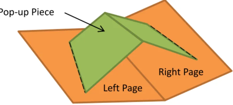
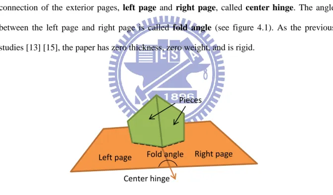
A scaffold consists of two exterior pages and several planar polygons, called pieces. The connection of the exterior pages, left page and right page, called center hinge. The angle between the left page and right page is called fold angle (see figure 4.1). As the previous studies [13] [15], the paper has zero thickness, zero weight, and is rigid.
Figure 4.1: Scaffold.
A scaffold only has left page and right page that are fully opened with 180°. To build a stable scaffold, two new connected pieces were added in each time. A pair of the new pieces is called an element. Before adding add an element, it needs to select two exist connective pieces (including left page and right page) in the current scaffold as the supporting pieces. The supporting pieces and the new pieces form a simple pop-up structure. Hence, an element consists of two pieces and records two supporting pieces. These pieces form four folding lines
Fold angle Center hinge
Right page Pieces
12
that converge on one point. Therefore, four vectors 𝑊, 𝑋, 𝑌 and 𝑍 could stand for as the axes for express the structure of the element, as the illustration in figure 4.2. Every point of pieces in the element can be spanned by two axes such as 𝑎𝑋 + 𝑏𝑍 or 𝑎𝑌 + 𝑏𝑍, the coefficients (𝑎, 𝑏) are the coordinates for the simulation of the pop-up.
Figure 4.2: The axes and angles in an element.
The angles between the axes are denoted as α, β, γ, and δ (figure 4.2). To be a foldable element, the angle conditions mentioned in equation (3.1) and equation (3.2) need to be satisfied. A limit fold angle θ is calculated by equation (3.1). In order to ensure the element can be opened without splitting it, the limit fold angle θ should be greater or equal than the angle between the two supporting pieces. Another condition equation (3.2) also should be satisfied for closing. If every element is foldable, then the whole scaffold is guaranteed to be stable.
4.2 V-fold Digraph
This thesis proposed a data structure to represent a v-fold scaffold, called v-fold digraph. A v-fold digraph G = (V, E) is an acyclic directed graph. V = {v0, v1, … , vn} is a set of
vertices, where v0 represent the exterior pages and other vertices represent elements individually. The two pieces of an element vk are denoted as l(vk) and r(vk). E =
{e0, e1, … , em} is a set of directed edges, where ek = (vi, vj) denote vi support vj, 𝛼 𝛽
𝛾 𝛿
Z
Y X
13 0 ≤ k ≤ m, 0 ≤ i, j ≤ n, i ≠ j. 𝑑𝑒𝑔−(v
i) is the number of directed edges entering vi. We
divide the vertices in V into different levels. The vertex v0 is the only vertex in level 0. The vertices pointed by v0 belong to level 1 and the vertices pointed by level 1 vertices belong to level 2, and so forth. If a vertex pointed by vertices that belong to different levels, then we put the vertex in the largest level. For example, if vertex vi pointed by a level 1 vertex and a level 2 vertex, then vi belongs to level 3.
(a) (b)
Figure 4.3: A v-fold pop-up and its v-fold digraph.
Figure 4.3 (a) presents an example of a v-fold pop-up. The exterior pages and the elements can be denoted by four vertices: v0, v1, v2 and v3. Where v1 supported by v0, v2
supported by v0 and v1, v3 supported by v1 and v2. The v-fold digraph of the pop-up is shown in figure 4.3 (b). There are some properties of a v-fold digraph:
1. 𝑑𝑒𝑔−(v0) = 0. That is, v0 is a source.
2. The element vi supported by one or two other element(s). 1 ≤ i ≤ n.
{𝑑𝑒𝑔𝑑𝑒𝑔−−(vi) = 1. if vi supported by one element. (vi) = 2. if vi supported by two element.
3. There are no directed cycles in a v-fold graph.
The first property is obvious because the exterior pages do not need support. The second
𝐯
𝟏𝐯
𝟎𝐯
𝟑𝐯
𝟐 Level 0 Level 1 Level 2 Level 3𝐯
𝟎𝐯
𝟏𝐯
𝟐𝐯
𝟑14
property means every element supported by one or two other element(s). If an element supported by another element, it means the element supported by two pieces of another element. In other hand, if an element supported by two other elements, it means the element supported by two pieces of the two other elements separately. If there is an element supported by three or more other pieces, the structure of this scaffold cannot be folded flat while maintaining its rigidity. Figure 4.4 (a) shows an example that an element supported by three pieces.
(a) (b)
Figure 4.4: (a) A structure that cannot be fold flat because the blue element supported by three pieces.
(b) An unstable structure that may collapse because the blue element and the red element support each other.
The third property ensures the v-fold structure is stable. Li et al. [15] propose a proposition of stability as follows:
A pop-up scaffold is stable if there is an ordering of pieces in the scaffold {𝑝1, 𝑝2, … } such
that 𝑝1, 𝑝2 are the left page and right page, and that for every k > 2, 1. Either 𝑝𝑘 connected with 𝑝𝑖 and 𝑝𝑗 where i, j < k, or
2. 𝑝𝑘 connected with 𝑝𝑘+1, and the two pieces connected with 𝑝𝑖 and 𝑝𝑗 where i, j < k. Because there are no directed cycles in a v-fold graph, the vertices could be separated to different levels. The elements were arranged from low to high according to their levels. The
15
ordering of elements can transform to the ordering of pieces. For example, an ordering {v0, v1, v2, v3} is calculated from the v-fold graph in figure 4.3 (b). Then the ordering of elements {v0, v1, v2, v3} can transform to the ordering of pieces { l(v0), r(v0), l(v1), r(v1), l(v2), r(v2), l(v3), r(v3) }. This ordering satisfies the proposition that Li proposed because the concept of levels is low level supported high level. Therefore, the acyclic property of v-fold graph ensures the stability of the pop-up structure. If there is a directed cycle in the v-fold graph, the structure is unstable that may collapse. An unstable example shows in figure 4.4 (b).
4.3 Animal Scaffold
This paper proposes the similar rules of the animal pop-up cards designed by Robert Sabuda (figure 3.2). These pop-up cards have fewer pieces and are designed for novices. Most of the animal pop-up cards exhibit the head or half-length of the animals. Generally, three types of animal scaffolds that are described as the following paragraphs.
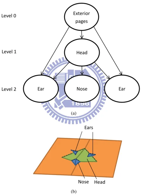
Head type is a pithy type that consists of head and ears. The head is supported by exterior pages, and the ears supported by the pieces of the head and exterior pages. Since some animals have significant characteristics on the face such as the nose of a pig, we add an optional element that is supported by head, shown as figure 4.5.
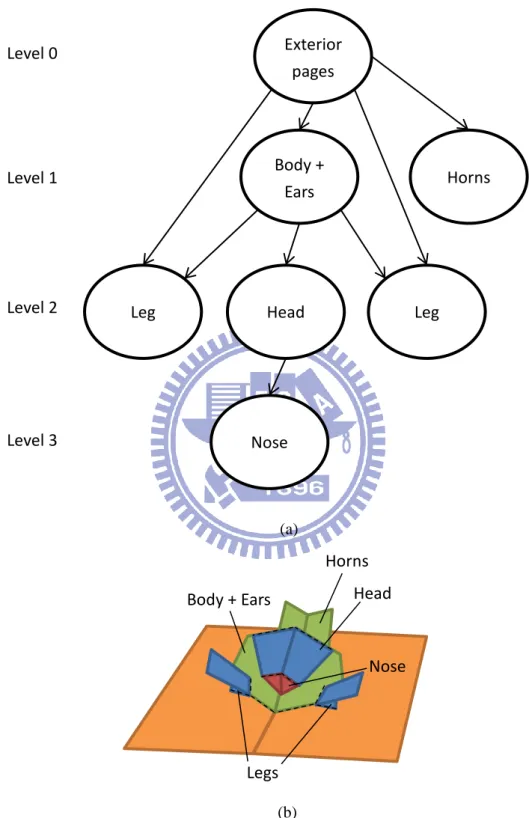
Bust type has more elements than head type. It consists of body, head, ears, forward legs, and horns. The body is as a base element that supports head and forward legs. We combine body and ears to a same plane like the reindeer in figure 3.2. The horns and nose are as optional elements that are supported by the exterior pages and the head element respectively, shown as figure 4.6.
16
Bird type consists of head, body, wings and tail. The head and body are combined to an element like the turkey in figure 3.2. The wings are supported by the pieces of body. The tail is as an optional element that under the body, shown as figure 4.6.
Figure 4.5: (a) The v-fold graph of head type. (b) The prototype of head type.
Level 0 Level 1 Level 2 Exterior pages Head Nose Ear Ear (a) Ears Head Nose (b)
17
Figure 4.6: (a) The v-fold graph of bust type. (b) The prototype of bust type.
Level 0 Level 1 Level 2 Level 3 Exterior pages Body + Ears Horns
Leg Head Leg
Nose (a) Head Horns Body + Ears Legs Nose (b)
18
Figure 4.7: (a) The v-fold graph of bird type. (b) The prototype of bird type.
Figure 4.5, 4.6, and 4.7 show the structures of different animal scaffolds. The v-fold digraphs indicate the supporting relations between the elements. These scaffolds can apply to four-leg animals and birds.
Wings Body + Head Tail (b) Level 0 Level 1 Level 2 Exterior pages Body + Head Tail Wings (a)
19
4.4 Pop-up Generation
The processing flow of pop-up generation is shown in figure 4.8. The preprocessing of the input mesh is segmentation and labeling. And then the pop-up generation starts with the left page and right page, and adds an element that conforms to defined animal scaffold iteratively. The order of adding element is from low level to high level. For example, to build a head type scaffold we first add a head element, and then add two ear elements, finally add a nose element. In each element generation, a 2D shape was extracted from the corresponding part of the mesh. The 2D shape was transformed to the pieces of the element. The details of the processes are described in the following paragraphs.
Figure 4.8: The processing flow of pop-up generation.
Feature Shape Attachment Output pop-up card Input Model Feature Shape Extraction Segmentation and Labeling
20
4.4.1 Mesh Segmentation and Labeling
First of all, the 3D mesh was segmented and labeled into corresponding parts. Segmentation has been extensively studied in the literature. In theory, our method works in combination with any segmentation algorithm. This paper proposes a scheme to pre-segment animal meshes using a benchmark [2]. Since automated labeling the parts is a challenging task that is related to shape recognition, the parts of the mesh was labeled manually.
4.4.2 2D Feature Shape Extraction
It is hard to find representative planes of the mesh, because the quality of the result planes depends on many factors such as coverage of features, human perception, and visual aesthetics. McCrae et al. proposed a powerful method to find a good planar shape proxy of a 3D mesh [17]. They learned the relative feature weights of different planes from user study data and derived a strategy to select planes that have more perceptual importance. Principal Components Analysis (PCA) plane is one kind of the candidate planes they considered. Therefore, the shape of mesh was computed using the PCA plane during 2D feature shape extraction.
For each part of the segmented mesh, the PCA axes were computed from the mesh vertices of the segment. The most and second significant eigenvectors form a plane that implies the principal direction of the segment. The 2D shape of the segment could be captured by projecting the surface vertices onto the plane. To find the contour points, a small cycle region was checked around the point. In this region, we sample some positions and compute a normal direction line that through this position, then check this line whether it intersects with the mesh segment. If one of the lines does not intersect with the mesh segment, the point was added to the contour list. An example is shown in figure 4.9 that one point on the contour and
21
another is not. After checking every point, the contour points were connected to form a 2D polygon. Though the polygons can express the shape of the 3D mesh, some orientations of polygons are not suitable for the defined scaffolds. In this case, we obtain another appropriate polygon by specifying a new plane manually.
Figure 4.9: The head of pig model and its projection result. The blue points indicate projected points
from mesh vertices. The black points mean sample points in red check region. Left: the point on the contour. Right: the point not on the contour.
22
4.4.3 2D Feature Shape Attachment
The 2D feature shapes were obtained in the above section. To attach them to the defined scaffold, the polygons should be rotated to the correct position. A rotate function 𝑅𝑜𝑡𝑎𝑡𝑒(𝑝, 𝑣⃑, 𝜃) means rotating a point p around an axis 𝑣⃑ by an angle 𝜃. The rotation is clockwise if 𝜃 is a positive value, and vice versa. The new position of point in the polygon is computed as
𝑃𝑔𝑜𝑎𝑙 = 𝑅𝑜𝑡𝑎𝑡𝑒(𝑃𝑜𝑟𝑖 , 𝑟⃑𝑎𝑥𝑖𝑠 , 𝜃). (4.1)
The term 𝑃𝑜𝑟𝑖 is the position of the original point in the polygon, and 𝑃𝑔𝑜𝑎𝑙 is the goal position of the point. The rotated axis 𝑟⃑𝑎𝑥𝑖𝑠 can be derived from the cross product of 𝑛⃑⃑𝑔𝑜𝑎𝑙 and 𝑛⃑⃑𝑜𝑟𝑖 that are shown in figure 4.10. And the rotated angle 𝜃 is the acute angle between the polygon plane and the goal plane. Note that the angle between the vectors 𝑛⃑⃑𝑔𝑜𝑎𝑙 and 𝑛⃑⃑𝑜𝑟𝑖 should be less than 90°. If it is not, we flip the sign of 𝑛⃑⃑𝑜𝑟𝑖 to keep the rotation clockwise.
Figure 4.10: Left: A polygon and its goal plane. Right: Viewed from above.
After rotation, the polygons are attached to the scaffold and become the pieces of the scaffold. For more flexibility, users could translate the piece on its plane slightly and adjust the angles between the axes under the restrictions. The points in the pieces can be spanned by the axes of the element, and the coordinates of the points could be stored. Finally the redundant regions were cut by another piece as a cutting plane (see figure 4.11), that can be
𝑛⃑⃑𝑜𝑟𝑖 𝑛⃑⃑𝑔𝑜𝑎𝑙 θ Polygon plane Goal plane 𝑟⃑𝑎𝑥𝑖𝑠
23
done by detecting the point whether it is at normal side of the cutting plane or not. Table 4.1, 4.2 and 4.3 show the cutting lists of the scaffolds. Figure 4.12 shows a head type scaffold before and after the cutting process.
Figure 4.12: Before and after cutting process. Figure 4.11: The piece cut by a cutting plane.
Cutting plane Be cut Be cut Cutting plane
24
Head
T
yp
e
Be cut Cutting plane
Left/Right piece of head Left/Right page Left/Right piece of head Right/Left piece of head
Left/Right piece of ears Left/Right piece of head (Left/Right piece of nose) (Right/Left piece of nose) (Left/Right piece of head) (Left/Right piece of nose)
Table 4.1: Cutting lists of the head type scaffolds.
B u st T yp e
Be cut Cutting plane
Left/Right piece of body Left/Right page Left/Right piece of body Right/Left piece of body Left/Right piece of body Left/Right piece of head Left/Right piece of head Left/Right piece of body Left/Right piece of head Right/Left piece of head Left/Right piece of legs Left/Right piece of body (Left/Right piece of horns) (Left/Right page) (Left/Right piece of horns) (Right/Left piece of horns)
(Left/Right piece of nose) (Right/Left piece of nose) (Left/Right piece of head) (Left/Right piece of nose)
25 B ird T yp e
Be cut Cutting plane
Left/Right piece of body Left/Right page
Right piece of body Left piece of body
Left/Right piece of wings Right/Left piece of wings (Left/Right piece of tail) (Left/Right page) (Left/Right piece of tail) (Right/Left piece of tail)
Table 4.3: Cutting lists of the bird type scaffolds.
4.5 Pop-up Simulation
To simulate pop-up animation, the positions of every piece could be computed in arbitrary fold angle 𝜃 between 0° to 180°. Four unit vectors W, X, Y, and Z were utilized as the axes to represent the folding lines of an element, as illustrated in figure 4.13. Since the points of pop-up pieces can be spanned by Y, Z or X, Z respectively, the positions of the points in the pop-up could be calculated from the current axes. In practice, the left page was fixed and the right page rotated toward it. In other words, Y and W are unchanged, and then X and Z rotate toward the left page. Finally, all vectors lie on the same plane at 𝜃 = 0.
Figure 4.13: The axes and angles in an element of a simple pop-up.
α β
γ δ
Z
Y X
W
Left Page Right Page
(0.8, 0.5)
26
Additionally, a complex pop-up consists of more than one element. According to mentioned concept above, each element has four axes to express its structure, as illustrated in figure 4.14. Note that Y and W are not always unchanged now. The algorithm for computing the axes of the elements at fold angle = 𝜃 is as follows:
Rotate the right page around center hinge by angle 180° −𝜃; For each element in the pop-up list
1. Obtain the new axes W, X, Y, Z ;
2. Compute the new positions of the pieces in the element; 3. Update the positions of the pieces in the element; End for;
The pop-up list consists of elements in level order. Hence, the positions of pieces were updated from low level to high level. The positions of level 0 pages (the two exterior pages) could be updated by rotating the right page. For level 1 element, the supporting planes are left page and right page. The axis W is unchanged since it always lies on the center hinge. For the element which is level 2 or higher level, the axis W was obtained from the normal of supporting planes:
𝑊 = 𝑛⃑⃑𝑠𝑢𝑝1× 𝑛⃑⃑𝑠𝑢𝑝2. (4.2) Furthermore, W could be rotated around the normal of supporting planes to get X and Y. The
Right Page Left Page Level 1 Level 0 Level 2 Level 2
Figure 4.14: The axes in a complex pop-up. W Z X Y X Y Z W Z X W Y
27 negative angle means the rotation is counterclockwise:
𝑋 = 𝑅𝑜𝑡𝑎𝑡𝑒(𝑊 , 𝑛⃑⃑𝑠𝑢𝑝1 , −𝛿). (4.3) 𝑌 = 𝑅𝑜𝑡𝑎𝑡𝑒(𝑊 , 𝑛⃑⃑𝑠𝑢𝑝2 , 𝛾). (4.4) Moreover, Z could be calculated by X, Y, α, and β, as shown in figure 4.15. The arguments 𝑎 to 𝑓 are lengths of line segments. The vector P on the XY plane is the projection of Z and we normalize P to unit length. The angle between X and Y is φ and the angle between X and P is ω. The vector P was obtained by rotating X with angle ω, where ω = φ ∙ α (α + β)⁄ . Then Z could be computed by:
𝑍 = 𝑅𝑜𝑡𝑎𝑡𝑒(𝑃, 𝑛⃑⃑𝑟𝑜𝑡, −𝜎). (4.5) Where 𝑛⃑⃑𝑟𝑜𝑡 is the cross product of P and the normal of XY plane, and 𝜎 is the angle
between P and Z that is given by:
σ = cos−1(𝑎2+ 𝑏2− 𝑐2
2𝑎𝑏 ).
𝑎 = 1, 𝑏 = 𝑒
cos 𝜔, 𝑐 = √𝑓2− 𝑑2, 𝑑 = 𝑏 ∙ sinω, 𝑒 = cosα, 𝑓 = sinα. The argument 𝑎 is 1 because Z has unit length, then 𝑒 and 𝑓 can be computed since the
β φ
Z
Y
d
c
b
𝑎
e
X
P
ω αf
σFigure 4.15: Find axis Z by given X, Y, α, and β.
28
triangle formed by 𝑎, 𝑒, 𝑓 is a right triangle. After 𝑒 is known, we can get 𝑏 and 𝑑. The argument 𝑐 can be obtained by Pythagorean Theorem. Finally, the angle σ can be computed by law of cosines.
After computing the four axes, the pieces of the element can be updated from its spanning axes. Then the updated elements that have lower level become an input to higher level elements. Finally, all elements in the pop-up list are updated to correct position at specified fold angle. Figure 4.16 explains the animation key frames during a pop-up card opening or closing.
Figure 4.16: A v-fold pop-up in deferent fold angles.
29
CHAPTER 5
Experimental Results
All 3D animal models are from a segmentation benchmark [2] that each model is roughly axis aligned, centered to origin, normalized to unit box, and creates manual segmentations by people. The pop-up generation starts with a segmented model. After labeling by users, the system generates a pop-up prototype that conforms to a defined scaffold, and then users can move the piece on its belonging plane until it looks good. Finally, the system cut the redundant region of pieces to complete the pop-up. Users can check the pop-up animation and then make the actual pop-up card manually.
Figure 5.1 shows a head type result of pig model and its intermediate states at various fold angles. The model has 10 segments and the system utilizes head, ears, and nose to generate pop-up. Figure 5.2 demonstrates a bust type of dairy cattle model. This type has more pieces than head type. The model has 10 segments and the head, horns, ears, body, and forward legs are employed. This type needs a small patch to support the horns that ensure the horns connect with the base pages. Figure 5.3 displays a bird type of goose model that has 8 segments. The head, body, wings, and tail are used to generate pop-up. The folding lines of wings are almost parallel that converge at a very far but finite point. The intermediate states of the pop-up viewed form bottom are also shown in figure 5.3. The actual pop-up cards are also shown in figure 5.1, 5.2 and 5.3. These pop-up cards could be made easily and their behavior similar to our simulation.
30
Figure 5.1: Top: The input model and segmentation. Middle: Result of pop-up with head type. Bottom:
31
Figure 5.2: Top: The input model and segmentation. Middle: Result of pop-up with bust type. Bottom:
32
Figure 5.3: Top: The input model and segmentation. Middle: Result of pop-up with bird type. Bottom:
33
The more experimental results are shown in figure 5.4 and figure 5.5. The mostly computation time of pop-up generation is finding the contour points within seconds that depends on the triangle number of the model. The pieces are adjusted by users within few minutes and the system executes the cutting process within one second.
34
Figure 5.5: Lamb in bust type and swallow in bird type.
There are some limitations of this proposed scheme. The animal scaffold cannot apply to every type of animals, such as fishes, insects, or reptiles. Some models that use the proposed algorithm are not performing well because we only use partial segments of the model. The characteristics of animals are various that need different scaffold to express it, such as camel's hump, kangaroo’s pouch, and so forth. The possible solution is allowing designers to build suitable scaffolds or finding representative planes of the model then make them “pop-upable”.
35
CHAPTER 6
Conclusion and Future Work
This thesis proposed a method to generate an animal pop-up card from a 3D model. Additionally, this thesis provided a v-fold diagraph to express the v-fold pop-up scaffold. The properties of v-fold graph ensure the pop-up structure can be opened and closed successfully. We generalize three types of animal scaffolds from the pop-up cards made by artist. The scaffolds could apply to birds and four-leg animals. The input mesh is segmented and labeled and then our system extracts the representative shapes of animal parts. These feature shapes are attached to the corresponding elements of the defined scaffold. Finally the system cut the redundant regions of the pieces to complete the pop-up card. Users can design an animal pop-up card in minutes with our system. The proposed algorithm also simulates the pop-up during it opened and closed. The pop-up animations can assist designers to understand how it works before make the pop-up manually.
There are few studies about generate 180° pop-ups from 3D models. We believe that this paper will inspires more research on pop-ups in the future. Currently, our system label the segments manually, combine our system with segmentation and shape recognition method such as Kalogerakis [10] can make this process automatic. Another improvement is considering more factors such as curvature and symmetry to find better planes for express the model. To transform other types of 3D models into pop-ups is also an interesting direction. A bigger challenge is explore more complex pop-up mechanism other than v-fold pop-up. For
36
example, add more than two pieces at a time. Considering the physical properties of paper such as thickness, weight, and warping is another practical extension that is closer to reality.
37
References
[1] CARTER, D. 1999. The Elements of Pop-up. Little Simon, New York.
[2] CHEN, X., GOLOVINSKIY, A., AND FUNKHOUSER, T. 2009. A Benchmark for 3D Mesh Segmentation. ACM Trans. Graphics 28, 3.
[3] DÉ CORET, X., DURAND, F., SILLION, F. X., AND DORSEY, J. 2003. Billboard clouds for extreme model simplification. In In Proc. SIGGRAPH, 689–696.
[4] DEMAINE, E., AND O’ROURKE, J. 2007. Geometric Folding Algorithms: Linkages, Origami, Polyhedra. Cambridge University Press, Cambridge.
[5] GLASSNER, A. 2002. Interactive pop-up card design, part 1. In Computer Graphics and Applications, IEEE. 22, 1, 79–86.
[6] GLASSNER, A. 2002. Interactive pop-up card design, part 2. In Computer Graphics and Applications, IEEE. 22, 2, 74–85.
[7] HARA, T., AND SUGIHARA, K. 2009. Computer aided design of pop-up books with two-dimensional v-fold structures. In 7th Japan Conference on Computational Geometry and Graphs.
[8] HILDEBRAND, K., BICKEL, B., AND ALEXA, M. 2012. crdbrd: Shape Fabrication by Sliding Planar Slices. Computer Graphics Forum, 31, 2, 583-592.
[9] HULL, T. 2006. Project Origami: Activities for Exploring Mathematics. A.K. Peters. [10] KALOGERAKIS, E., HERTZMANN, A., AND SINGH, K. 2010. Learning 3d mesh
segmentation and labeling. In ACM SIGGRAPH, 102:1–102:12.
[11] KAVAN, L., DOBBYN, S., COLLINS, S., ZA RA, J., AND O’SULLIVAN, C. 2008. Polypostors: 2d polygonal impostors for 3d crowds. In In Proc. I3D, 149–155.
[12] KILIAN, M., FLÖRY, S., CHEN, Z., MITRA, N. J., SHEFFER, A., AND POTTMANN, H. 2008. Curved folding. ACM SIGGRAPH 27, 3, 75:1–9.
38
of pop-up books. Computers & Graphics 20, 1, 21–31.
[14] LI, X.-Y., SHEN, C.-H., HUANG, S.-S., JU, T., AND HU, S.-M. 2010. Popup: automatic paper architectures from 3d models. ACM Transactions on Graphics 29, 4, 111:1–9.
[15] Li, X.-Y., Ju, T., Gu, Y., Hu, S.-M. 2011. A Geometric Study of V-style Pop-ups: Theories and Algorithms. ACM Transactions on Graphics 30, 4.
[16] MASSARWI F., GOTSMAN C., ELBER G. 2007. Papercraft models using generalized cylinders. In Proc. Pacific Graphics 2007, pp. 148–157.
[17] MCCRAE J., SINGH K., MITRA N. J. 2011. Slices: A shape-proxy based on planar sections. ACM Trans. Graph. 30, 6.
[18] MITANI, J., AND SUZUKI, H. 2003. Computer aided design for 180-degree flat fold origamic architecture with lattice-type cross sections. Journal of graphic science of Japan 37, 3, 3–8.
[19] MITANI, J., AND SUZUKI, H. 2004. Computer aided design for origamic architecture models with polygonal representation. In CGI ’04: Proceedings of the Computer Graphics International, IEEE Computer Society, Washington, DC. USA, 93–99.
[20] MITANI J., SUZUKI H. 2004. Making papercraft toys from meshes using strip-based approximate unfolding. ACM Trans. Graphics 11. 3, 259-263.
[21] MITANI, J., SUZUKI, H., AND UNO, H. 2003. Computer aided design for origamic architecture models with voxel data structure. Transactions of Information Processing Society of Japan 44, 5, 1372–1379.
[22] OKAMURA, S., AND IGARASHI, T. 2009. An interface for assisting the design and production of pop-up card. Lecture Notes in Computer Science 5531, 2, 68–78.
[23] O’ROURKE, J. 2011. How to Fold It: The Mathematics of Linkages, Origami, and Polyhedra. Cambridge University Press, UK.
39 Computer 22, 9, 825–834.
[25] TACHI, T. 2009. Origamizing polyhedral surfaces. IEEE Transactions on Visualization and Computer Graphics 16, 2, 298–311.
[26] TAKAHASHI, S., WU, H. Y., SAW, S. H., LIN, C. C., AND YEN H.C. 2011. Optimized Topological Surgery for Unfolding 3D Meshes. Computer Graphics Forum, 30, 7, 2077-2086.
[27] UEHARA, R., AND TERAMOTO, S. 2006. The complexity of a pop-up book. In 18th Canadian Conference on Computational Geometry.

![Figure 2.1: V-style pop-up [15]. (a) A v-style pop-up in fully opened state. (b) The Eiffel Tower pop-up constructed by automated algorithm](https://thumb-ap.123doks.com/thumbv2/9libinfo/8614205.190922/14.892.148.775.225.458/figure-style-opened-eiffel-tower-constructed-automated-algorithm.webp)