行政院國家科學委員會專題研究計畫 成果報告
整合 STEPml 及 WfMC 為核心技術之協同產品構型管理研
究
計畫類別: 個別型計畫 計畫編號: NSC92-2416-H-009-006- 執行期間: 92 年 08 月 01 日至 93 年 07 月 31 日 執行單位: 國立交通大學管理科學學系 計畫主持人: 張力元 共同主持人: 張瑞芬 計畫參與人員: 黃元珀 報告類型: 精簡報告 處理方式: 本計畫可公開查詢中 華 民 國 93 年 8 月 30 日
行政院國家科學委員會專題研究成果報告
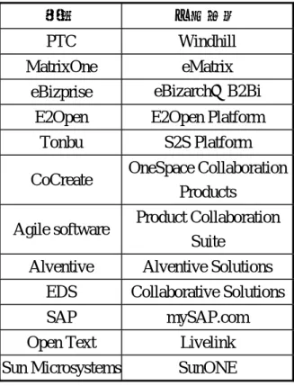
整合 STEPml 及 WfMC 為核心技術之協同產品構型管理研究(I) 計畫編號:NSC92-2416-H-009-006 執行期限:92 年 8 月 1 日至 93 年 7 月 31 日 計畫主持人:張力元 交通大學管理科學系 教授 一、中文摘要 本計畫為兩年期計畫,主要研究目的 在建立一個網路應用平台架構以展示跨國 合作之產品型態及協同設計案例。依此主 題,本計畫有下列五項主要研究任務: 1. 建立接單式設計之產品組態模型技術 2. 設計一應用架構作為客戶端與伺服端請 求回應之溝通形式 3. 調查以 STEP-XML 為基之資料交換標 準,以促進產品組態資料於網路環境之 流通分享 4. 發展一模組化、以網路為基之協同商務 工作流程 (Workflow) 技術 5. 建立網路應用平台架構以展示跨國合作 之產品型態及協同設計案例 依階段性計畫目標,本年度(第一年 度)主要完成了下列預期工作項目: 1. 回顧相關 CPC 文獻與產品構型軟體 2. 定義 CPC STEP-XML 標準 3. 定義 ETO 之 XML schema 4. 定義協同架構 5. 發展產品構型之模式化技術 6. 發展產品構型搜尋策略與演算法 關鍵字:STEPml、產品資料管理、網路協 同產品商務、工作流程管理 二、前言 以顧客為 導向之 網路 協同產品 商務 (Collaborative Product Commerce, CPC)是 近年來興起之熱門研究主題。網路協同產 品商務能夠協助供應鏈體系相關企業(協 力廠商的製造設計團隊)及客戶,在產品 生產開發流程中不受時空限制,即時存取 與管理產品及流程資訊,更快速回應市場 需求,合作開發出符合客戶需求之產品, 提昇客戶滿意度,並節省產品開發成本與 時間。 一個完善之網路協同產品商務解決方 案需要落實以客戶為導向之設計,並大量 客製化,需有下列幾項關鍵技術之發展: 1. 產品型態定義與分析:定義產品結構等 資訊,並依據顧客需求、設計限制,搜 尋分析可能之組成產品型態,包括三個 主要模組: A. 產品定義模組 B. STEP-XML 轉換模組 C. 產品型態分析引擎模組 2. 工作流程管理 為期達到對此關鍵技術之發展與應用 方法有更深入的了解,本研究期以兩年的 研究歷程,以建立一個網路應用平台架構 以展示跨國合作之產品型態及協同設計案 例為主要目的。 三、文獻探討 3.1 協同產品商務概念 協同產品商務又視為 c-Commerce,就 是基於協同設計系統的概念下所發展出來 的,它的概念主要是於 1998 年,由知名調 查 研 究 機 構 Aberdeen Group 與 Gartner Group 所提出。它的目標在於希望產品開發流程的資訊,能夠與企業其他相關資源進 行整合,並進一步提昇企業的競爭力,獲 取優勢。它是以產品為中心的解決方案, 它藉由線上生產知識與現有的企業應用系 統的分享,來整合產品生命週期。 網路協同產品商務系統發展最早者首 推 參 數 科 技 (Parametric Technical Corporation, PTC),目前,網路協同產品商 務的主要產品供應商很多,而互相多有某 種程度的合作關係。相關協同產品商務系 統與產品構型軟體部份列舉如表 1。 表 1 協同產品商務系統與構型軟體 廠商 主要產品 PTC Windhill MatrixOne eMatrix
eBizprise eBizarch™ B2Bi
E2Open E2Open Platform
Tonbu S2S Platform
CoCreate OneSpace Collaboration
Products
Agile software Product Collaboration
Suite
Alventive Alventive Solutions
EDS Collaborative Solutions
SAP mySAP.com
Open Text Livelink
Sun Microsystems SunONE
3.2 STEP 簡述
STandard for the Exchange of Product data model (STEP)提供一種產品資訊的表 示方式。此表示式,為一種中性的產品資 料模型表示式,使得產品資料易於交換, 且此資料格式不受任何一個系統所支配。 其目的在於,以有效的與有意義的方式, 將所有圖像與非圖像資料作適當的關連, 以致於在所有的 CAM system 間,產品資料 得以獲得完整的描述。STEP 模型的功能不 僅在於檔案交換,亦在於實作、紀錄與分 享產品資料庫 (ISO 10303-1, 1994)。整個 STEP 分為許多部分,而其目的是為了要完 整地、正確地描述產品資料。圖 1、圖 2 為 2002 年為止 ISO 10303 所有的 Parts。從 系 統 導 入 觀 點 , STEP 的 標 準 於 ISO-201~240, 對程式撰寫者來說是一個非 常方便的協定集合。此集合可使得系統撰 寫者相當容易的選擇到其相對應的領域。 而在定義系統資料模組方面,系統撰寫者
可 以 參 考 general resource (ISO
10303-41~54)與 application resource (ISO 10303-101~109) 將系統的模組架構出。
•101 Draughting •104 Finite element analysis •105 Kinematics
107 Finite element analysis definition relationships
108 Parameterization and constraints for explicit geometric product models 109 STEP assembly model for products
Integrated application resource Application protocol
•201 Explicit draughting •202 Associative draughting •203 Configuration controlled design •204 Mechanical design using boundary
representation
•207 Sheet metal die planning and design •209 Composite and metallic structural analysis
and related design
•210 Electronic assembly, interconnection, and packaging design
•212 Electrotechnical design and installation •214 Core data for automotive mechanical design
processes 215 Ship arrangement 216 Ship moulded forms 218 Ship structures
221 Functional data and their schematic representation for process plants •224 Mechanical product definition for process
planning using machining features •225 Building elements using explicit shape
representation 226 Ship mechanical systems •227 Plant spatial configuration •232 Technical data packaging core information
and exchange
233 Systems engineering data representation 236 Furniture product data and project data 239 Product life cycle support 240 Process plans for machined products
Abstract test suite
302 Associative draughting •304 Mechanical design using boundary
representation 305 Mechanical design using surface
representation
•307 Sheet metal die planning and design 312 Electrotechnical design and installation 314 Core data for automotive mechanical design
processes 318 Ship structures
•324 Mechanical product definition for process plans using machining features 325 Building elements using explicit shape
representation
329 Exchange of design and manufacturing product information for forged parts •332 Technical data packaging core information
and exchange
333 Systems engineering data representation 336 Furniture product data and project data
Application interpreted construct
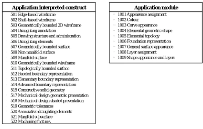
•501 Edge-based wireframe •502 Shell-based wireframe •503 Geometrically bounded 2D wireframe •504 Draughting annotation •505 Drawing structure and administration •506 Draughting elements •507 Geometrically bounded surface •508 Non-manifold surface •509 Manifold surface •510 Geometrically bounded wireframe •511 Topologically bounded surface •512 Faceted boundary representation •513 Elementary boundary representation •514 Advanced boundary representation •515 Constructive solid geometry •517 Mechanical design geometric presentation •518 Mechanical design shaded presentation •519 Geometric tolerances •520 Associative draughting elements 521 Manifold subsurface 522 Machining features Application module •1001 Appearence assignment •1002 Colour •1003 Curve appearance •1004 Elemental geometric shape •1005 Elemental topology •1006 Foundation representation •1007 General surface appearance •1008 Layer assignment •1009 Shape appearance and layers
圖 2 STEP 組成–Part 501~522、1001~1009 為了達到資料交換共享的目標 STEP 中 定 義 了 一 套 資 料 模 型 建 構 語 言 EXPRESS (ISO 10303-11, 1994)協助完成 資料模型的建構。EXPRESS 是一種物件導 向式的模型建構語言,因此除了用以完成 標準模式建構外,後續相關的資料之整 合、延伸亦可凸顯 EXPRSS 中性語法的優 點 。 就 EXPRESS 技 術 之 應 用 而 言 , Trappey、Liu 與 Hwang (1997)著眼於 PCB 產業的組裝流程,其研究中利用 EXPRESS 建構印刷電路板產業之零組件資料模型, 並將產品資料存放於物件導向式資料庫 (Object Store)中,作為後續之可組性分析之 基礎。 然而,在應用中 STEP 提供異質環境 產品下交換之媒介,實則要有效運用這些 產品資料,則需仰賴另一機制統籌管理這 些產品資料。在本計畫研究中,則使用 PDM Schema 作為統籌管理的機制,以使得平台 與平台之間的交換資料誤差不至於有太大 的落差。 3.3 PDM Schema 簡述 PDM Schema (PDM Schema, 2002)為 STEP 的一部份,但並非正式的 AP 而是一 種相同需求與資料結構之所有一般性的 STEP Application Protocol 集合。其文件由 ProSTEP 與 PDES, Inc.共同發展出來,而運 用範圍於 AP-203、AP-212、AP-214、AP-232 如圖 3 所示,而其從事範圍如圖 4 所示。
由圖 3 中可以大略的得知到,PDM Schema 所主要參照到的 Part 與製造之組裝設計有 關。在圖 4 中可看出 PDM Schema 功能單 元群 (unit of function, uof),而紅框中的零 件 管 理 代 表 著 本 計 畫 研 究 所 會 使 用 到 uof。而 STEPml 本身亦以 PDM Schema 作 為其資料模組之表示方式,故在研究中的 資料互通性上,則不構成問題。
203 Configuration Controlled design 212 Electronical assembly, interconnection and packing design 214 Core data for automotive mechanical design processes
232 Technical data packaging core information and exchange
圖 3 PDM Schema 之定位與內容 Part Management Part Identification Part Classification Part Structure Part Properties Document Management Document Identification File Identification Document Structure Document/ File Properties Alias Identifi-cation Effec-tivity Confi-guration Authorization Person and Organization Date and Time Approval Security Classification Contract And Project Work and Change Management Part Properties External Geom. Model Transformation Part Management Part Identification Part Classification Part Structure Part Properties Document Management Document Identification File Identification Document Structure Document/ File Properties Alias Identifi-cation Effec-tivity Confi-guration Authorization Person and Organization Date and Time Approval Security Classification Contract And Project Work and Change Management Part Properties External Geom. Model Transformation Part Management Part Identification Part Classification Part Structure Part Properties Part Management Part Identification Part Classification Part Structure Part Properties Document Management Document Identification File Identification Document Structure Document/ File Properties Document Management Document Identification File Identification Document Structure Document/ File Properties Alias Identifi-cation Effec-tivity Confi-guration Authorization Person and Organization Date and Time Approval Security Classification Authorization Person and Organization Date and Time Approval Security Classification Contract And Project Work and Change Management Part Properties External Geom. Model Transformation Work and Change Management Part Properties External Geom. Model Transformation 圖 4 PDM Schema 之使用範圍與本計畫研 究之焦點 PDM Schema 文 件 由 ProSTEP 與 PDES, Inc. 共 同 發 展 出 來 , 其 Units of Function (UoF)之模組包含: 1. 產品辨識 2. 零件分類 3. 零件性質 4. 產品結構與關連 5. 文件辨識 6. 文件分類 7. 外部檔案
8. 文件與組成檔案關連 9. 文件與檔案屬性 10. 文件與檔案產品資料的關連 11. 文件與檔案關係 12. 別名鑑識 13. 授權 14. 型態與有效資訊 15. 工作管理資料 3.4 STEPml 簡述 STEPml 是以 PDM Schema 之模組為 基礎。許多企業以網路為基來「減少轉運 成本」、「開闢新市場」、「對顧客提供 更優的服務」。但在以網際網路為基之時, 這些考量項目僅僅都是以產品資料的角度 作為觀察的視野,但卻忽略了產品的資 訊、企業的資訊、商品的設計與其製造。 因為工程資料並非由簡單的展開表而衍生 出,故對工程資料而言,以往對於使用 XML 包含在其中就變成了一種疑慮。在 2002 年底,由 ISO/TS 團隊開發出的「ISO 10303-28 -- Product data representation and exchange : Implementation methods : XML : representation of EXPRESS schemas and data」即利用 ISO 10303 之完整性,針對這 些忽略的項目所想出來的概念,而衍生出
的 ISO 10303-28 , STEPml 藉 由
ISO10303-28 中─ OSEB ─此 binding 發 展成為一個針對產品資料的 XML markup 語言,其是從 STEP 而來的資訊模組。為 了支援對網路 STEP 和模組的發展,NIST 領導網路為基礎的儲存處(repository),發展 一個以 STEP 模組發展環境的核心。大略 來說,STEPml 之重點在於 PDM 領域,其 在 於 : 1. 產 品 定 義 與 分 類 2. 產 品 結 構 (http://www.stepml.org) , 且 規 格 採 自 於 OSEB,其規格於 ISO10303-28 中有大量的 討論。換句話說,目前 STEPml 採取的資 料模組為 PDM Schema 但目前所發展的階 段僅置於產品定義與分類與產品結構等。 故在本研究中,使得 STEP 與 STEPml 以 PDM Schema 作為統一的資料模組則是可 行的,但僅行於此兩部分。
STandard for the Exchange of Product data model XML (STEPml)為一個專為產品 的 XML 的 規 格 庫 。 為 了 能 夠 瞭 解 STEPml,故吾人從 ISO 10303-28 開始著 手,AP-28 使用 XML 來詳細說明 EXPRESS schema 以便於資料的統整。以下為此 AP 之適用範圍(ISO, 2002): 1. 內部範圍: XML markup 宣 告 敘 述 使 用 , 使 得 EXPRESS schema 得以在 XML 再展現。 且單一的 XML markup 宣告敘述的使用 集合為獨立的 EXPRESS schema。在此 用法之下,ISO 10303 允許展示資料於一 些選擇。 2. 外部範圍: 若有一個已知的 XML markup 宣告集 合,以及一個或是多個與其對應的資料 集合,可以藉此建立 EXPRESS schema, 而此 EXPRESS schema 也保含了 XML markup 中語法所包含的資料。但此要求 為一種意義與資料的使用的瞭解,才得 以做到此目的。 四、研究成果 4.1 STEP 與 STEPml 轉換過程 要進行產品零件之協同設計,必須先 將產品規格進行轉換,才能由系統進行零 件辨識(Part Identification)。 在先前的探討中,可知產品辨識可藉 由 EXPRESS-G 表示,其分區意義:「part I 表示領域資訊的部分,part II 表示零件主 要辨識的部分,part III 表示型態分類的部 分」,完整的 EXPRESS-G 圖如圖 5。
product_related_pr oduct_category#1 product_related_pr oduct_category#2 product_category_r elationship sub_category category products S[1:?] products S[1:?] of_product product_definition_f ormation product_definition formation application_context _element=>prodcut _definition_context #1 frame_of_frame application_context #3 frame_of_frame product frame_of_reference S[1:?] application_context _element=>product _context application_context #1 frame_of_reference application S[1:?] application_protoco l_defintion Part I Part III Part II 圖 5 產品辨識完整圖 由於定義內容需求很多,本報告僅列 出 Part I 表示法作為代表,並省略其中詳盡 說明部份。 Part I:分 1-7 項說明零件領域資訊中各個 實體之相關程式碼轉換內容。 1. Product 實體 其 EXPRESS 程式碼為: ENTITY product; id : identifier; name : label;
description : OPTIONAL text;
frame_of_reference : SET[1:?] OF product_context; END_ENTITY;
所對應的 DTD 為:
<!ELEMENT Product EMPTY> <!ATTLIST Product
x-id ID #REQUIRED Description-r IDREF #IMPLIED Frame_of_reference-r IDREF #REQUIRED Id-r IDREF #REQUIRED Name-r IDREF #REQUIRED>
因在 PDM Schema 之 EXPRESS 檔中, 另有規範出 identifier、label 以及 text 這 三種 Type 屬於 String 之型態,故在 STEP 或是 Part 21 之檔案填入資料時,直接填 入字串值即可。相對應的,在 STEPml 所 使 用 的 DTD 當 中 亦 有 規 範 除 Identifier、Label 與 Text,經由指定其 x-id 屬 性 值 後 再 來 填 入 其 資 料 值 。 故 在 Product 的 DTD 方面 id 轉為 Id-r、name 轉 為 Name-r 、 description 轉 為 Description-r 、 frame_of_reference 轉 為 Frame_of_reference-r。而資料庫中設定 Product 之表格與欄位即以 DTD 當中所 擁有的屬性名來命名之。 2. Application_context_element 其 EXPRESS 程式碼為: ENTITY application_context_element SUPERTYPE OF (ONEOF(product_concept_context, product_context, product_definition_context)); name : label; frame_of_reference : application_context; END_ENTITY; 所對應之 DTD 為:
<!ELEMENT Application_context_element EMPTY> <!ATTLIST Application_context_element
x-id ID #REQUIRED Frame_of_reference-r IDREF #REQUIRED Name-r IDREF #REQUIRED>
application_context_element 底下,有三 個立即子類別(Immediate Subtypes)。在 產品主要辨別中,若是 product 參照的時 候,則是需要參照於 product_context; 若是 product_definition 參照時,則是參 照於 product_definition_context。而在此 處可看到 Application_context_element 之 DTD 屬性,在往後的 Product_context 與 Product_definition_context 皆須繼承此實 體中之屬性。 3. Product_concept_context 其 EXPRESS 碼為: ENTITY product_concept_context SUBTYPE OF (application_context_element); market_segment_type : label; END_ENTITY; 其對應的 DTD 碼為:
<!ELEMENT Product_concept_context EMPTY> <!ATTLIST Product_concept_context
x-id ID #REQUIRED Market_segment_type-r IDREF #REQUIRED Frame_of_reference-r IDREF #REQUIRED Name-r IDREF #REQUIRED>
Product_concept_context 為
application_context_element 之子型態, 其繼承了父型態之所有值再加上其本身 之定義值。但在產品主要辨識中,並沒 有使用到 product_concept_context 此物
件,故在本研究中並沒有將此表格加於 資料庫中。 4. Product_context 其 EXPRESS 程式碼為: ENTITY product_context SUBTYPE OF (application_context_element); discipline_type : label; END_ENTITY; 其對應的 DTD 則為:
<!ELEMENT Product_context EMPTY> <!ATTLIST Product_context
x-id ID #REQUIRED Discipline_type-r IDREF #REQUIRED Frame_of_reference-r IDREF #REQUIRED Name-r IDREF #REQUIRED>
product_context 為 application_context_element 之子型態, 其繼承了父型態之所有值再加上其本身 之定義值,而其 XML 之屬性定義方式亦 如同此方式定義。而在產品主要辨識 中,其被 Product 實體參照,故在 Product 之 Frame_of_reference-r 之屬性中需指定 至本實體之 x-id 中。資料庫的欄位則可 由上述之 DTD 屬性中可看出。 5. Product_definition_context 其 EXPRESS 程式碼為: ENTITY product_definition_context SUBTYPE OF (application_context_element); life_cycle_stage : label; END_ENTITY; 而其對應之 DTD 為:
<!ELEMENT Product_definition_context EMPTY> <!ATTLIST Product_definition_context
x-id ID #REQUIRED Life_cycle_stage-r IDREF #REQUIRED Frame_of_reference-r IDREF #REQUIRED Name-r IDREF #REQUIRED>
product_definintion_context 為 application 之子型態,其繼承了父型態之所有值再 加上其本身之定義值,而其 XML 之屬性 定義方式亦如同此方式定義。 6. Application_context 其 EXPRESS 程式碼為: ENTITY application_context; application : label; DERIVE
description : text := get_description_value(SELF); id : identifier := get_id_value(SELF); INVERSE
context_elements : SET[1:?] OF application_context_element FOR frame_of_reference; WHERE wr1 : SIZEOF(USEDIN(SELF,'PDM_SCHEMA.' + 'DESCRIPTION_ATTRIBUTE.DESCRIBED_ITEM')) <= 1; wr2 : SIZEOF(USEDIN(SELF,'PDM_SCHEMA.' + 'ID_ATTRIBUTE.IDENTIFIED_ITEM' )) <= 1; END_ENTITY; 其對應的 DTD 為:
<!ELEMENT Application_context EMPTY> <!ATTLIST Application_context
x-id ID #REQUIRED Application-r IDREF #REQUIRED D-Description-r IDREF #IMPLIED D-Id-r IDREF #IMPLIED I-Context_elements-r IDREFS #IMPLIED W-Wr1 ( true | false | unknown ) #IMPLIED W-Wr2 ( true | false | unknown ) #IMPLIED>
此實體介紹了這份檔所使用到的應用領 域。在產品辨識當中,由 product_context 與 application_protocol_definition 參照到 這個實體。如同 STEPml 所敘述的,在 INVERSE 處需將 context_elements 對應 至 XML 時須加上”I-“,而 WHERE 的 Local rule 則需要加上”W-“並且為(true | false | unknown)的。資料庫之建置方式亦 請參考 DTD 所指出之屬性,以及其性 質。 7. Application_protocol_definition 其 EXPRESS 程式碼為: ENTITY application_protocol_definition; status : label; application_interpreted_model_schema_name : label; application_protocol_year : year_number; application : application_context; END_ENTITY; 其對應之 DTD 碼為:
<!ELEMENT Application_protocol_definition EMPTY> <!ATTLIST Application_protocol_definition
x-id ID #REQUIRED
Application-r IDREF #REQUIRED Application_interpreted_model_schema_name-r IDFEF #REQUIRED Application_protocol_year CDATA #REQUIRED Status-r IDREF #REQUIRED>
Application_protocol_definition 為定義此 應用協定為何種,是在 ISO 10303 當中 的應用協定中的何種協定。例如:吾人 可 以 設 定 Status-r 為 version1.2 , 而 application_interpreted_model_schema_na me-r 則設定成 pdm_schema;此時即代表
吾 人 使 用 的 應 用 協 定 為 pdm_schema version1.2。而可指定應用協定之年與應 用於哪一個 application_context。 4.2 產品構型之模式化技術及策略 圖 6 為產品構型之模式化導入方法。 系統架構是將目標訂定於設立一平台,使 得不同體系得以在線上進行其各自之資料 交換,而本研究中舉協同設計為例,希望 能夠達到未來在 STEP 與 STEPml 之間相容 性之目的;於系統中,兩種不同的資料交 換規格必須可互相交換。因此在系統轉換 之核心部分,以 STEP-Tool. Inc.所發展出 之 ST-XML 作為 XML 檔案與 STEP 檔案之 轉換機制核心。 在此茲將本系統導入過程介紹如下: 首先,以 PDM Schema 作為 EXPRESS 實 體模組,登錄至 ST-Develop 之 system_db 中使得 OSEB 轉換系統得以啟動。其次, 以 ST-XML 之 OSEB 轉換產生 XML 檔或 STEP 檔。在最後開發一整合介面作系統輸 出輸入之控管。而系統產生 STEP 檔或 XML 檔後,皆成 XML 檔再統一存入資料 庫中。 PDM Schema作為 EXPRESS實體模組 ST-XML之OSEB作 為轉換核心 產生STEP檔 產生XML檔 整合介面 圖 6 產品構型之模式化導入 以一個協同設計流程為例,將系統中 設計主廠商與協力廠商互動做一說明,其 示意圖如圖 7。流程解釋如下: 主廠商 格式轉換器 需求送出 需求分配 正確格式 需求資料庫 協力廠商 需求通知 格式轉換器 設計資料 溝通協調 設計回饋 錯誤通知 規格資料庫 設計 資 料 不通過項目 通過項目 格式轉換 通過資料 產品型錄商 Web Service 圖 7 系統概念圖 1. 由於完善的瞭解產品結構與設計,為協 同產品設計時十分重要的事情,故當設 計主廠商與客戶協商出一產品,而主廠 商將其設計專案向系統下需求,使得系 統上可以很明顯的分別出產品之結構與 該設計之元件。換句話說,在需求單除 了包含產品被組裝之零件外,亦需包含 產品所需之規格。另外一點,在本研究 當中不論是 STEP 檔或是 XML 檔,在本 系統中皆可接受。 2. 當需求提出至系統之後,系統得以剖析 需求單中之內容與設計結構,並且存入 資料庫中。以系統中協力廠商之資料, 選定各元件協同合作之廠商,選定後以 電子郵件的方式,發送出該元件之需求 通知。 3. 當協力廠商收到需求通知後,藉此得知 設計需求,則可經由網際網路至本系統 中,將產品設計資料樣本與樣本之圖檔 上傳至系統中,不同格式之廠商可藉由 格式轉換模組,統一將資料交換成 XML 模式在系統上運行。 4. 當系統收到各個協力廠商已發送過來之 設計資料,則將這些設計資料之 XML 剖析之後存入資料庫之中,以作為目前 樣本版本之記錄。 5. 在系統中獲得資料後,即以電子郵件的 方式通知設計主廠商,目前有何種零件
已到達,請設計主廠商至中介系統上下 決策,參與決定協力廠商之競標。 6. 主設計廠商可依據競標廠商所傳遞過去 之樣本設計資料,決定何家廠商得標且 該零件廠商之設計樣本是否需要再更改 下一版本版次之樣本 (超越客戶期望)。 而系統將諮詢該樣本是否仍有瑕疵 (亦 即仍可超越客戶期望之步驟),由此步驟 當中系統發電子郵件給予得標且仍有瑕 疵之協力廠商,通知該廠商需上傳設計 資料,重複步驟 3。直到主廠商對於設 計樣本符合卓越需求為止。 7. 待設計資料確定完成之後,此系統經由 檢視型錄讓設計主廠商選擇欲顯示在型 錄商上之項目。各元件完成後至系統之 Catalog Information 中即可即時將剛設 計完成之產品經由 Web Service 上傳至 型錄廠商,得到型錄廣告之效果。 在 系 統 中 資 料 庫 如 同 一 儲 藏 處 (Repository),如圖 8 所示,如此作法是為 了要儲存所有相關的訊息,諸如:產品辨 識、產品結構…等。而所有的供應商皆可 以 Web 介面至體系之介面中心來存取資料 庫,進而達到協同設計之資料交換的目的。 Internet XML資料剖析 DataBase as Repository ST-XML轉換 系統角色: 設計主廠商 協力廠商 廠商以STEP為基 廠商以STEPml為基 XSLT轉換 型錄之XML檔 產品型錄商 Web Service 圖 8 系統架構圖 由圖 8 中可看出,廠商若指的是協力 廠商們,可能會因各個使用之格式標準而 有所不同,而欲將兩種標準於系統中運 行,運轉之概念如圖 9。 中介系統 ST-XML STEP Files DataBase as Repository XML Files STEP STEPml 廠商1 Based on STEP 廠商2 Based on STEPml 上傳 上傳 下載 下載
Product Rule in EXPRESS Formate
圖 9 系統檔案轉換圖 圖 9 中,系統中心之中介系統如前所 述的以 XML 為基底,再者,若協力廠商支 援 STEPml 時:如圖中右側,直接將 XML 檔案剖析後,存入資料庫,而欲將設計資 料 給 予 其 他 格 式 之 廠 商 , 則 需 透 過 ST-XML 轉成 STEP 格式,再給予該廠商下 載。 若支援 STEP 時:如圖中之左側,當 STEP 檔上傳至中介系統後,利用 ST-XML 轉為 XML 格式以利後續剖析、存入資料庫 之用,而欲將 XML 格式之社記資料給於其 他格式之廠商,即可將此檔案給予下載。 轉換之系統之目的在於建構一資料交 換平台,使得一組裝體系得以在線上進行 協同設計之資料交換,最終的目標即是主 廠商可透過此機制,得到協力廠商之彙整 資料,而得到專業分工、資訊透明化優點。 五、結論與計畫成果自評 本計畫第一年度進度,已依工作項目 逐項完成,請參考本報告第三節與第四節 之描述。為建立一資料交換平台,本計畫 研究首先針對 STEP、與 PDM Schema 作一 介 紹 與 探 討 , 而 為 了 達 到 交 換 平 台 以 STEPml 為基,本研究則是在探討與介紹 STEPml 與 STEP 之間之不同以及其交換之
方式,希望藉此得到符合 ISO 130303 - 28 規範之零件管理部分之資料庫規格。 在不同的產品資料管理系統下,彼此 之格式有所不同,但共同遵循 PDM Schema 之規範,透過網路技術,設計主廠商與協 力廠商即可快速協議正確、及時的產品資 料。本論文的完成可歸納出幾項成果: 1. 以 STEPml 為基的系統開發,增進資料 格式共通的可行性。由於 PDM 系統所包 含的資料相當廣泛,若缺乏共通的標準 將造成資料格式的不一致,因而喪失資 料交換的意義;而 PDM Schema 的設計 即是為了產品資料交換的需求而來。系 統 以 STEPml 為 基 , 自 然 便 以 PDM Schema 為基,採用 PDM Schema 作為資 料交換標準,不但可作為系統與系統之 間轉換之一致性的根基,亦可以使得資 料完整性有一定程度的保障。 2. 跨越設計製造與商務兩階段之連結,使 得產品型錄擁有即時性。在以往的產品 資料的交換與傳遞,將設計、製造與商 務以不同方式分別傳遞,商務資料交換 格式以一些著名的資料交換標準,如 Rosettanet…等,來進行商務上之資料的 交換。相對的 PDM 系統之間的傳遞亦是 由各公司之間所依循之格式互相傳遞設 計製造方面的資料,如 STEP…等。而本 研究著重於使用 STEPml,即在於強調 STEPml 為一種 markup language,可藉 由 XSLT 之轉換至商務資料交換標準所 需之格式,使得設計製造與商務兩階段 獲得連結。在經由 World-Wide-Web 網 路通訊標準的普及,使得轉換資料之時 間與成本減縮,進而擁有即時性,主要 設計廠商僅需透過瀏覽器即可完成產品 型錄的製作。 3. 產品之設計內容可依循客戶所需之要求 增減,增進產品設計之客製化。產品設 計的過程中,不但要求資料的正確性, 亦需強調客戶之需求以及即時修改之便 利性。透過網際網路的便利性,一旦客 戶所訴諸之要求有所更改,產品設計變 更在修改後可有效的通知協力廠商,進 而增進客製化時設計變更之便利性。 六、參考文獻
[1] Bailey, I., “Requirements Specification for EXPRESS Mapping Language,” EuroSTEP Limited (1997).
[2] Chiu, M. L., “An organizational view of design communication in design collaboration,” Elsevier Science Ltd., 23(2), 206-207 (2002).
[3] CIMData, Product Data Management: The Definition, CIMData World, MI, 8-9 (1997).
[4] Construction IT, STEP standard,
http://cic.vtt.fi/links/step.html.
[5] Cover Pages: STEP/EXPRESS and XML,
http://xml.coverpages.org/stepExpressX ML.html.
[6] Daggett, T., Positioning STEP for Web Use, Electric Boat Division & General Dynamics (2001).
[7] Gao, J., “A Market Survey of Industrial Requirement for Product Data Management and Manufacturing Planning System,” Proceedings of the 1999 IEEE International Symposium on Assembly and Task Planning (ISATP '99), Porto, Portugal, 106 -111 (1999). [8] Gu, P., and Chan, K., “Product
Modeling Using STEP,” Computer-Aided Design, 27(3), 163-179 (1995).
[9] ISO 10303-1, Industrial automation systems and integration – Product data representation and exchange – Part 1: Overview and fundamental principles, International Organization for Standardization, Geneva, Switzerland (1994).
[10] ISO 10303-11, Industrial automation
systems and integration – Product data representation and exchange – Part 11: Description methods: The EXPRESS language reference manual, International Organization for Standardization, Geneva, Switzerland (1994).
[11] ISO 10303-21, Industrial automation
systems and integration – Product data representation and exchange - Part 21: Implementation methods: Clear text encoding of the exchange structure, International Organization for Standardization, Geneva, Switzerland (1994).
[12] ISO/TS 10303-28, Product data
representation and exchange: Implementation methods: XML representations of EXPRESS schemas and data, International Organization for Standardization, Geneva, Switzerland (2002).
[13] Jackson, M., “Efficient collaboration
between main and sub-supplier,” Computer in Industry, 27-29 (2002). [14] Kappel, G., and Vieweg, S., Database
Requirement of CIM Applications, http://citeseer.nj.nec.com/correct/35685 4 (1993).
[15] Key, C., and Madden, D., “Critical
data management,” International Journal of Micrographics & Optical Technology, 13(4), 191-194 (1995). [16] Liang, J., Shah, J. J., Souza, R. D.,
Urban, S. D., Ayyaswamy, K., Harter, E., and Bluhm, T., “Synthesis of consolidated data schema for engineering analysis from multiple STEP application protocols,” Computer-Aided Design, 31, 429-447 (1999).
[17] Rachuri, S., Interoperability standard for exchange of design, product, process, and business information over
the semantic web, http://avi.im.isu.edu.tw/proceedings/ijie
2001/FINAL/SUDARSAN.PDF, 4-6 (2001).
[18] SCRA, Inc., “ISO 10303 STEP
Application Handbook version 2,” http://www.isg-scra.org/STEP/files/ST EP_Application_Handbook.pdf (2001).
[19] STEP-Product data Standard,
http://www.soberit.hut.fi/T-86/T-86.141 /s2001/STEP_ESI.pdf.
[20] Ungerer, M., Buchanan, K., “Usage
Guide for the STEP PDM Schema V1.2,” PDM Implementor Forum (2002).
[21] Yao, Y.H., Trappey, A.J.C., “ISO
10303 compatible data model and its application for PC configuration management,” PERGAMON, 339-352 (1999). [22] 彭定國 (指導教授:張瑞芬 教授), 「建構以 STEP 資料模組之工程資料 管理系統」,國立清華大學博士論文, 第 33-34 頁 (1997)。
[23] 彭定國、張瑞芬,「以 STEP 為基礎 構建整合性產品資料管理雛形系統」, 工業工程學刊,第十七卷,第一期, 第 90-95 頁 (2000)。 [24] 游子興 (指導教授:張瑞芬 教授), 「考慮接單是生產與型態管理之個人 電 腦 產 品 資 料 管 理 系 統 設 計 與 建 置」,國立清華大學碩士論文 (1999)。 [25] 簡君穎 (指導教授:張瑞芬 教授), 「以網際網路為基之工作流程管理系 統設計」,碩士論文,清華大學工業 工程所 (2001)。 [26] 羅詠盛 (指導教授:張瑞芬 教授), 「整合產品資料交換標準及網際網路 應用技術於企業間產品資料交換系統 之研發」,國立清華大學碩士論文 (2000)。