Liquid crystal surface alignments by using ion beam sputtered magnetic thin films
Hsin-Ying Wu and Ru-Pin Pan
Citation: Applied Physics Letters 91, 074102 (2007); doi: 10.1063/1.2770763
View online: http://dx.doi.org/10.1063/1.2770763
View Table of Contents: http://scitation.aip.org/content/aip/journal/apl/91/7?ver=pdfcov Published by the AIP Publishing
Articles you may be interested in
Effect of ion beam energy on density, roughness & uniformity of Co film deposited using ion beam sputtering system
AIP Conf. Proc. 1447, 691 (2012); 10.1063/1.4710191
Detection of alignment changes at the open surface of a confined nematic liquid crystal sensor J. Appl. Phys. 105, 123504 (2009); 10.1063/1.3148861
Interdependence between stress, preferred orientation, and surface morphology of nanocrystalline TiN thin films deposited by dual ion beam sputtering
J. Appl. Phys. 99, 113519 (2006); 10.1063/1.2197287
Study of annealed Co thin films deposited by ion beam sputtering J. Vac. Sci. Technol. A 24, 74 (2006); 10.1116/1.2135292
Photorefractive Bragg gratings in nematic liquid crystals aligned by a magnetic field Appl. Phys. Lett. 74, 3459 (1999); 10.1063/1.124127
This article is copyrighted as indicated in the article. Reuse of AIP content is subject to the terms at: http://scitation.aip.org/termsconditions. Downloaded to IP: 140.113.38.11 On: Thu, 01 May 2014 00:20:11
Liquid crystal surface alignments by using ion beam sputtered magnetic
thin films
Hsin-Ying Wu and Ru-Pin Pana兲
Department of Electrophysics, National Chiao Tung University, Hsinchu, Taiwan 30010, Republic of China
共Received 6 June 2007; accepted 19 July 2007; published online 13 August 2007兲
A method for liquid crystal surface alignment by using a one-step, ion beam bombardment of the glass substrates is demonstrated. Precoating by polyimide is not necessary. The authors show that the homeotropic alignment is achieved due to orientation of the diamagnetic nematogenic molecules by the magnetic field from the ␥-Fe2O3 ferrimagnetic thin films created on the substrates by ion
beam bombardment. The film exhibits a high Curie temperature well above 300 K and a compensation temperature which is the typical feature of ferrimagnetism. This is a simple, noncontact, and reliable alignment method for liquid crystal devices. © 2007 American Institute of
Physics. 关DOI:10.1063/1.2770763兴
It is well known that the liquid crystal 共LC兲 molecules can be reorientated by electric and magnetic fields due to their anisotropic electrical permittivity and magnetic susceptibility.1 In the past decades, the electro-optical effect of nematic liquid crystals 共NLCs兲 has been widely used in liquid crystal displays 共LCDs兲. On the other hand, surface alignments of liquid crystals are essential in fabrication of LCDs and other LC devices. It determines the boundary con-dition for the molecular orientation at the surface. Currently, the most common alignment method used in LCD industries is the rubbing method, which employs a velvet rubbing pro-cess on polyimide共PI兲 coated on substrates. In spite of its success, this method has some drawbacks such as leaving debris and electrostatic charges on the rubbed surfaces.2 Be-sides, it becomes increasingly difficult to maintain unifor-mity as the substrate size of LCD gets larger rapidly in in-dustry. In order to enhance the qualities of LC products, noncontact alignment methods are highly desirable. One of the alternative alignment methods, ion beam共IB兲 alignment, had been reported by the IBM group.3–5They have realized this noncontact alignment technology by integrating low en-ergy ion beam equipments and diamondlike carbon 共DLC兲 thin films into LCD manufacturing processes. The mecha-nism of this alignment method was attributed to the aniso-tropical change of bindings between carbon atoms caused by ion beam bombardment.5 Over the past few years, several studies devoted to ion beam bombarded DLC and PI films have also been reported.6–8 One of the most remarkable re-sults is that the homeotropic alignments can be obtained by using fluorinated DLC thin films as the alignment layer and the pretilt angle can also be controlled by choosing different ion beam parameters or the concentration of fluorine doped in DLC films.8 In addition, both homogeneous and homeo-tropic alignments can be obtained with the same kind of organic alignment layers bombarded by ion beams with dif-ferent energies.6,7 This remarkable ability of controlling the alignment modes makes the ion-beam alignment method po-tentially useful in LC-based applications, especially in LCDs industry.
Recently, we have reported that both homogeneous and homeotropic alignments can be induced by argon ion beam bombardments with low and high energies, respectively, on
the same kind of polyimide film 共SE-130B, from Nissan Chemical Industries, Ltd.兲.9
However, the alignment mecha-nisms were still to be clarified.
In this letter, we unambiguously demonstrate that even the glass substrates without PI films, bombarded with high energy ion beam 共HEIB兲, can achieve homeotropic align-ment of the LCs. This is a reliable alignalign-ment method for LC devices. We will show that the homeotropic alignments are due to the field from the magnetic thin films created on sub-strates by ion beam bombardment, based on the systematic analyses on x-ray photoemission spectroscopy 共XPS兲, ultraviolet-visible spectroscopy共UV/Vis兲, and superconduct-ing quantum interference device共SQUID兲 data.
We employ a direct-current 共dc兲 diode-type ion beam sputter10 共model IB-2 from EIKO Engineering Co., Ltd.兲 for ion beam treatments. The sputter can be used either as a coating or etching device, depending on the polarity of the voltage. When the etching mode is selected, the bottom elec-trode, on which the sample substrates are set, acts as the cathode. The substrates are etched by ion beams from in-duced glow discharge near the top electrode. For the coating mode, the bottom electrode is chosen as the anode, the sample substrates are then uniformly coated with the target material mounted on the top. Stainless steel electrode is used for the top electrode. With an attached sample holder, the incidence angle, bombarding time, current density, and the energy of ions are all controllable parameters in our system. The energy of ions is varied by changing the dc voltage between electrodes. Before each ion beam process, the cham-ber is pumped down to a base pressure of 30 mTorr and then argon gas is fed into the chamber to a target pressure of 55 mTorr.
The indium tin oxide共ITO兲 coated glasses with area of 20⫻10 mm2are used as the substrates. The thickness of ITO
layer measured by using ellipsometry is 167 nm. After clean-ing, the substrates are directly treated by ion beams共etching mode兲 without any PI coating. The ion energy, current den-sity, incidence angle, and bombarding time for ion beam treatment are 1120 V, 255A / cm2, 60°, and 5 min,
respec-tively. We should use the notation共ion energy, current den-sity, incidence angle, and bombarding time兲 for parameters of ion beam treatment in the following text. Then two sub-strates are combined together with a 23m Mylar spacer in between to form an empty cell with an antiparallel
arrange-a兲Electronic mail: [email protected]
APPLIED PHYSICS LETTERS 91, 074102共2007兲
0003-6951/2007/91共7兲/074102/3/$23.00 91, 074102-1 © 2007 American Institute of Physics This article is copyrighted as indicated in the article. Reuse of AIP content is subject to the terms at: http://scitation.aip.org/termsconditions. Downloaded to IP:
ment. The liquid crystal 4
⬘
-n-pentyl-4-cyanobiphenyl共5CB兲 共Merck兲 with a nematic range between 24.0 and 35.3 °C is then filled into the empty cell for alignment characterization. Figure 1 shows the optical micrographs of 5CB cells between crossed polarizers. The 5CB cell with substrates coated with ion beam treated PI films shows good homeotro-pic alignments because the good dark state is observed while rotating the cell, as shown in Fig.1共a兲.9Remarkably, the cell employing two substrates without PI films also shows the homeotropic alignment关see Fig.1共b兲兴. The conoscopic pat-terns shown in the insets further indicate achievement of the homeotropic alignment.To find out the possible mechanisms for alignment, we have carried out XPS共PHI-1600 from Physical Electronics, Inc.兲 analyses on the substrate surface. Three kinds of samples, 共i兲 as-deposited PI film, 共ii兲 HEIB-etched PI film, and共iii兲 HEIB-etched ITO film 共without PI兲, are scanned in survey mode with a step size of 1 eV and analyzer pass energy of 117.4 eV. The data are shown in Fig.2. A signifi-cant amount of Fe element is found in the compositions of samples共ii兲 and 共iii兲 but not in sample 共i兲. The Fe 2p and Fe 3p core-level signals are located in the ranges of 705–735 and 53– 60 eV, respectively.11The signals between 530 and 700 eV are confirmed to be the Auger signals of Fe.12Based on these results, we deduce that the Fe element is sputtered
from the electrode while the ion sputter is operated with HEIB.
For a detailed study of the Fe peaks, the multiplex mode scanning of Fe 2p region on HEIB-etched PI film is carried out with a step size of 0.2 eV and analyzer pass energy of 23.5 eV. The result is shown in the inset of Fig.2. According to the literatures,13,14 the shake-up satellite line at 718.2 eV is a characteristic of Fe3+in Fe
2O3. Further, the narrow peak
at 710.4 eV of the Fe 2p spectrum indicates that no Fe2+iron oxidation state exists. In other words, the possibility of form-ing Fe3O4 共magnetite兲 in the film can be excluded. The film
should be composed of the Fe3+ oxides, Fe
2O3 only. The
spectrum of the HEIB-etched ITO film reveals the same pro-file. Structurally, however, there are four possible types of Fe2O3. Two of them, ␣-Fe2O3 共hematite兲 and ␥-Fe2O3
共maghemite兲, are common and widespread in soils.15
Of the two, only the␥-Fe2O3 has permanent magnetic moments.
The XPS Fe 2p3/2 signals of HEIB-etched PI and ITO films have been analyzed quantitatively with deconvolution technique.16–18The results also conclude that the treated sub-strate is coated with a film of␥-Fe2O3. We have also coated
a substrate without PI using the ion sputter in coating mode with the beam parameters of 1120 V, 255A / cm2, 0°, and
20 min. The XPS spectrum is almost the same as that for films sputtered in etching mode.
Moreover, the UV/Vis absorbance spectrum of the film sputtered with coating mode is also measured and plotted in Fig.3. The spectrum shows that this sample exhibits better transparency in the visible spectral region and does not have the typical absorption peak for ␣-Fe2O3 in the UV region
from 300 to 380 nm.19–22These results also support our as-sertion that the coated iron oxide films are of the particular allotropic form, i.e.,␥-Fe2O3.
Since␥-Fe2O3is a magnetic material, we have also
mea-sured the magnetic dipole moments of the films sputtered in the coating mode to verify its magnetic property. A SQUID 共MPMS-XL7, Quantum Design兲 equipped with a supercon-ducting magnet with maximum strength of 70 kOe has been used for this measurement. The typical sensitivity of the magnetization measurement is better than 1⫻10−8emu 共H
⬍2.5 kOe兲. The total magnetization 共M兲 of the sample pre-pared in the coating mode with ion conditions of 1120 V, 255A / cm2, 0°, and 30 min is measured as a function of
temperature 共T兲 from 75 to 350 K in an applied field of 300 Oe. The measured M-T curve is shown in the inset of
FIG. 1.共Color online兲 Polarizing optical microscope photographs of NLC cells treated by HEIB:共a兲 with PI film coating and 共b兲 without PI film coating共inset: conoscopic pattern, A: analyzer, and P: polarizer兲.
FIG. 2. Measured Mg K␣-excited core-level spectra of共i兲 as-deposited PI film,共ii兲 IB-etched PI film, and 共iii兲 ITO films with conditions of 1120 V, 255A / cm2, 60°, and 5 min. Inset: the measured Fe 2p spectrum in mul-tiplex mode of film共ii兲.
FIG. 3. UV/Vis absorbance spectrum of iron oxide thin film with ion con-dition of共1120 V, 255A / cm2, 0°, and 20 min兲. Inset: temperature depen-dence of the magnetization for the iron oxide film with ion conditions of 1120 V, 255A / cm2, 0°, and 30 min in an applied field of 300 Oe. 074102-2 H.-Y. Wu and R.-P. Pan Appl. Phys. Lett. 91, 074102共2007兲
This article is copyrighted as indicated in the article. Reuse of AIP content is subject to the terms at: http://scitation.aip.org/termsconditions. Downloaded to IP: 140.113.38.11 On: Thu, 01 May 2014 00:20:11
Fig.3. This curve shows a minimum that corresponds to the compensation temperature, a typical feature of ferrimagnetism.23The Curie temperature reported in the lit-erature for␥-Fe2O3is in the range from 820 to 986 K.15This
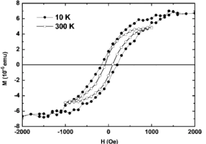
is well above our measuring temperature and the operating temperature of common LC devices. The characteristic hys-teresis loops expected for ferrimagnetic films are obtained at 10 and 300 K. These are shown in Fig.4after correction for the diamagnetic component at high field due to the quartz substrate. We note that the magnetization of our sample is measured with the magnetic field parallel to the film surface. More studies about the domain structure and magnetic prop-erties of the coated iron oxide thin film are in progress.
Through systematic measurement and analyses as de-scribed above, we have confirmed that the sputtered films are iron oxides composed of ferrimagnetic␥-Fe2O3. Moreover, because of aromatic rings on the molecular axis of typical nematogenic molecules such as the 5CB, such LC molecule exhibits positive anisotropy in the diamagnetic susceptibility
a. Therefore, the magnetic field H due to the ferrimagnetic
film can exert a torque ⌫=a共n·H兲n⫻H on the LC
mol-ecule, where n is the unit vector for average molecular ori-entation and the direction of optical axis.1As a result, ho-meotropic alignment of 5CB is achieved on a HEIB-treated substrate.
Since the torque on LC molecules is proportional to the square of magnetic field, the film may consist of small do-mains having magnetic dipole mainly perpendicular to the surface but with alternating signs. The magnetic field is strong enough at the surface to align the LC molecules but decreases rapidly away from the surface. The surface bond-ing due to the molecular-orbital interactions between the Fe atoms and cyanobenzene of 5CB should also contribute to the alignment mechanisms.24
We have also studied the surface anchoring energy and the electro-optical performance of a LC cell using the HEIB-sputtered film as the alignment layer. The surface anchoring energy for 5CB is about 2.0⫻10−4J / m2 better than
3.4⫻10−5J / m2 of commonly used surfactant, N ,
N-dimethyl-N-octadecyl-3-aminopropyltrimethoxysilyl chlo-ride 共DMOAP兲. Furthermore, the magnetic thin films can also be used to achieve homogeneous alignment after some treatments. We have also found out that the sputtered films
are composed of nanoscaled clusters of␥-Fe2O3particles by
using the atomic force microscope.
In conclusion, we unambiguously demonstrate that ITO coated glass substrates with or without PI films, after bom-bardment using the dc diode sputter with ion energy of 1120 V and current density of 255A / cm2, can achieve ex-cellent homeotropic alignment of the LCs. We show that the homeotropic alignment is achieved due to orientation of the diamagnetic nematogenic molecules by the magnetic field from the ␥-Fe2O3 ferrimagnetic thin films created on the
substrates by ion beam bombardment. The films exhibit a high Curie temperature well above 300 K and a compensa-tion temperature which is the typical feature of ferrimag-netism. This is a simple, noncontact, and reliable alignment method for LC devices. It can be easily scaled for manufac-turing of large-size LC television panels.
The authors would like to thank Wen-Bin Jian and Chin-Lun Lin for help with the SQUID measurements. This work is supported in part by MOE-ATU Program and the National Science Council of R.O.C. under Grant No. NSC 95-2221-E-009-249, and PPAEU-II.
1P. G. deGennes and J. Prost, The Physics of Liquid Crystals, 2nd ed. 共Oxford, New York, 1993兲, pp. 117–139.
2S. Kobayashi and Y. Iimura, Proc. SPIE 123, 2175共1994兲.
3P. Chaudhari, James Lacey, Shui-Chih Alan Lien, and James L. Speidell, Jpn. J. Appl. Phys., Part 2 37, L55共1998兲.
4P. Chaudhari, J. Lacey, J. Doyle, E. Galligan, S. C. Alan Lien, A. Callegari, G. Hougham, N. D. Lang, P. S. Andry, R. John, K. H. Yang, M. Lu, C. Cai, J. Speidell, S. Purushothaman, J. Ritsko, M. Samant, J. Stöhr, Y. Nakagawa, Y. Katoh, Y. Saitoh, K. Sakai, H. Satoh, S. Odahara, H. Nakano, J. Nakagaki, and Y. Shiota, Nature共London兲 411, 56 共2001兲. 5J. Stöhr, M. G. Samant, J. Lüning, A. C. Callegari, P. Chaudhari, J. P.
Doyle, J. A. Lacey, S. A. Lien, S. Purushothaman, and J. L. Speidell, Science 292, 2299共2001兲.
6S. H. Lee, K. H. Park, J. S. Gwag, T. H. Yoon, and J. C. Kim, Jpn. J. Appl. Phys., Part 1 42, 5127共2003兲.
7J. S. Gwag, K. H. Park, J. L. Lee, J. C. Kim, and T. H. Yoon, Jpn. J. Appl. Phys., Part 1 44, 1875共2005兲.
8H. J. Ahn, S. J. Rho, K. C. Kim, J. B. Kim, B. H. Hwang, C. J. Park, and H. K. Baik, Jpn. J. Appl. Phys., Part 1 44, 4092共2005兲.
9H. Y. Wu, T. T. Tang, C. C. Wang, R. P. Pan, S. J. Chang, and J. C. Hwang, Mol. Cryst. Liq. Cryst.共accepted兲.
10B. Chapman, Glow Discharge Processes: Sputtering and Plasma Etching 共Wiley, New York, 1980兲, pp. 185–188.
11M. Descostes, F. Mercier, N. Thromat, C. Beaucaire, and M. Gautier-Soyer, Appl. Surf. Sci. 165, 288共2000兲.
12D. Briggs and J. C. Rivière, in Practical Surface Analysis, edited by D. Briggs and M. P. Seah 共Wiley, Chichester, 1990兲, Vol. 1, Chap. 3, pp. 117–119.
13C. R. Brundle, T. J. Chuang, and K. Wandelt, Surf. Sci. 68, 459共1977兲. 14Y. Gao and S. A. Chambers, J. Cryst. Growth 174, 446共1997兲. 15R. M. Cornell and U. Schwertmann, The Iron Oxides: Structures,
Proper-ties, Reactions, Occurrences, and Uses, 2nd ed.共Wiley-VCH, Weinheim,
2003兲, pp. 1–7.
16D. A. Shirley, Phys. Rev. B 5, 4709共1972兲.
17R. P. Gupta and S. K. Sen, Phys. Rev. B 10, 71共1974兲.
18A. P. Grosvenor, B. A. Kobe, M. C. Biesinger, and N. S. Mclntyre, Surf. Interface Anal. 36, 1564共2004兲.
19Y. S. Kang, D. K. Lee, and C. S. Lee, J. Phys. Chem. B 106, 9341共2002兲. 20B. Z. Tang, Y. Geng, J. W. Y. Lam, B. Li, X. Jing, X. Wang, F. Wang, A.
B. Pakhomov, and X. X. Zhang, Chem. Mater. 11, 1581共1999兲. 21J. D. Desai, H. M. Pathan, S. K. Min, K. D. Jung, and O. S. Joo, Appl.
Surf. Sci. 252, 2251共2006兲.
22V. Goossens, J. Wielant, S. Van Gils, R. Finsy, and H. Terryn, Surf. Inter-face Anal. 38, 489共2006兲.
23S. Foner, in Magnetism, edited by T. Rado and H. Suhl共Academic, New York, 1963兲, Vol. I, Chap. 9, pp. 415–419.
24P. N. Sanda, D. B. Dove, H. L. Ong, S. A. Jansen, and R. Hoffmann, Phys. Rev. A 39, 2653共1989兲.
FIG. 4. Magnetization curves for an iron oxide thin film sputtered in coating mode with ion conditions of 1120 V, 255A / cm2, 0°, and 30 min at T = 10 K and 300 K in the magnetic field parallel to the film surface.
074102-3 H.-Y. Wu and R.-P. Pan Appl. Phys. Lett. 91, 074102共2007兲
This article is copyrighted as indicated in the article. Reuse of AIP content is subject to the terms at: http://scitation.aip.org/termsconditions. Downloaded to IP: 140.113.38.11 On: Thu, 01 May 2014 00:20:11